Harol CA430 User manual

Assembly instruction
Awning
CA430
art.nr. 19454

- 2 -V3-12-09
Assembly instructions awning CA430
Contents
A. Introduction page 2
B. General warnings ! page 2
C. List of tools required page 2
D. Fitting instructions page 3
E. Electrical connections + motor page 8
F. Trouble-shooting page 11
A. Introduction
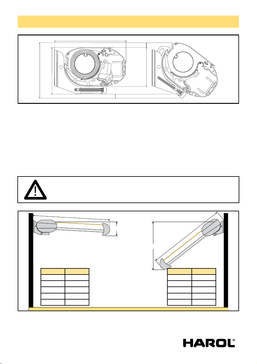
The CA430 awning is a closed and very compact cassette awning.
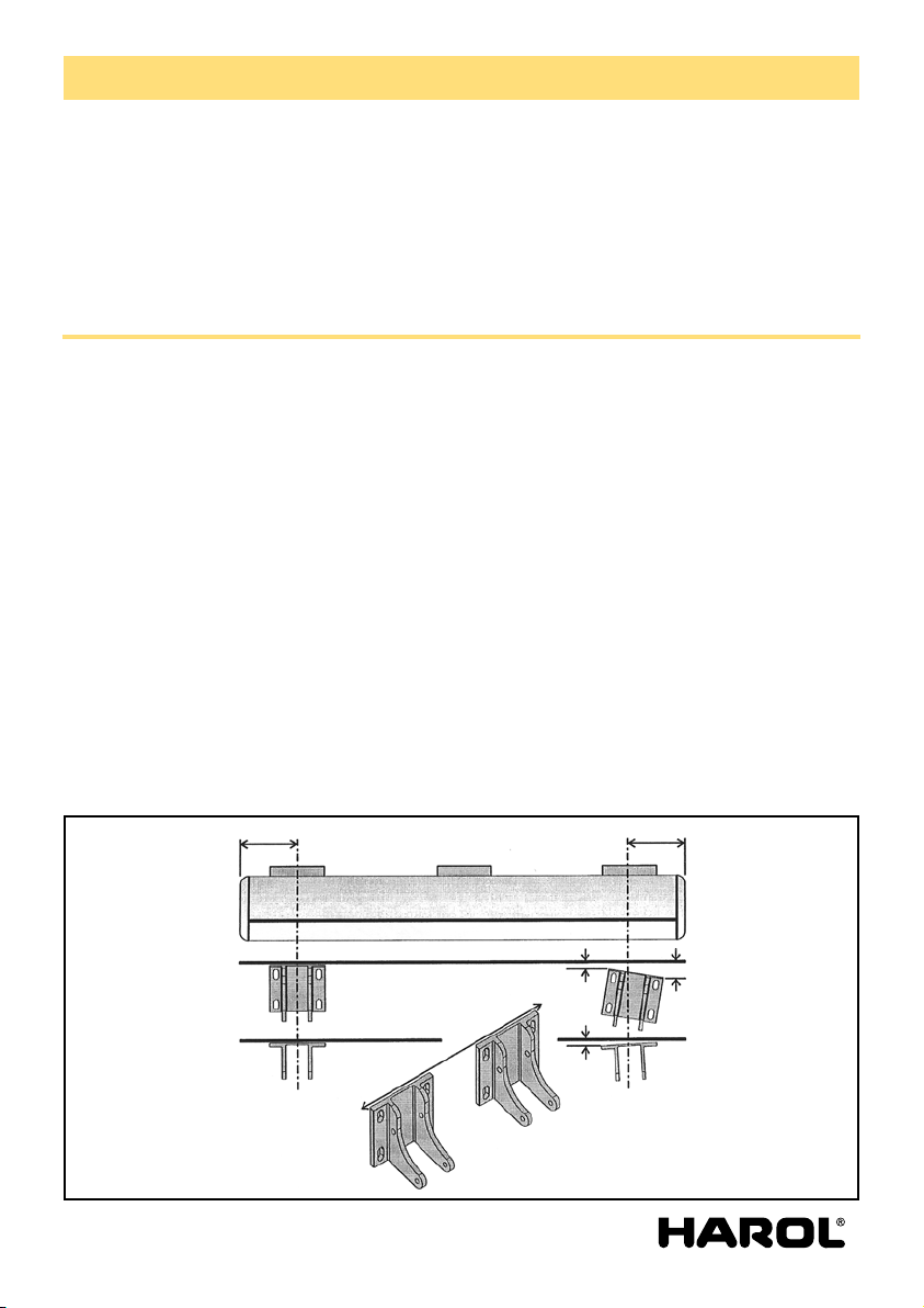
The system is characterized by its strong supporting bottom profile, which serves as a support on
which the consoles, the projection arms and the roller tube are suspended or slid into. The standard
type of this construction ( 2 arms) permits a projection of 3,5 meters and a width of 6 meters.
B. General warnings !
For a safe fitting, use and maintenance of this sun protection a number of precautions have to be
taken. For the safety of everyone concerned, please do take notice of the following general warnings !
! This manual is meant to be used by professionals only! It is not to be used bij DIY-enthusiasts or
apprentice fitters.
! Before you start ,please do read these instructions thoroughly.
! Be very careful and make sure of a solid footing whilst operating
! Provide sufficent light in the fitting area. Dispose of obtsacles and dirt. Make sure that, except for the
fitters, no other people are in the fitting area. Unauthorized people might be in
the way or at risk themselves.
! Whilst operating the system, you must be able to overlook the complete area and the whole of the
sun protection. There are a number of places where people might get injured. Especially watch the
following parts where people might risk getting jammed : the folding arms, the extension pole and
the casing.
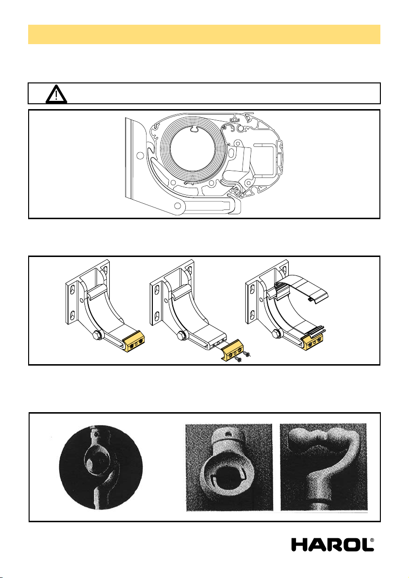
! Folding arms are always under considerable tension, a tension created by their own springs. There-
fore, be careful and work safely.
! Electrical connections have to be made in accordance with the existing local norms and requirements.
! Our products must be installed so that all parts remain accessible at all times for maintenance and
eventual repairs. If this is not the case, Harol cannot be held responsible for any additional costs (f.e.
demolition activities, repairs to facades and interior walls) as a result of this.
C. List of tools required
- Ladders
- Snap-off blade knife
- Drill
The awning has been designed as a sun protection and for that reason it may not be
used as an all-weather protection. In case of heavy rain or wind the awning has to be
closed immediately. Therefore we recommend to use the sun protection in combina-
tion with an automated wind/sun – control.

- 3 -V3-12-09
Assembly instructions awning CA430
- 19 mm open-ended spanner or ring spanner
- Tape measure and pencil
- Voltmeter or test lamp
- Masonry drill Ø6 mm + Ø14 mm
- Allen keys 4 mm + 6 mm
- Spirit level
- Cord
D. Assembly manual CA430
D.1. Opening the packaging:
Open the cardboard packaging. Be careful when cutting the strips with a knife, as the paintwork can be
easily scratched if the cardboard is not opened carefully. Only remove the plastic packing from around
the housing when the screen has been fixed to the wall.
D.2. Checking the contents:
The awnings are supplied ready for assembly, provided with the necessary screws. Attachment mate-
rial for wall mounting has to be chosen by the assembler himself – various chemical plugs are on the
market for such circumstances. For this take comprehensive advice from your supplier of attachment
materials. The company Harol accepts no responsibility for any assembly screws that come loose.
Check the contents of the packing and count it accurately, then check the most important measure-
ments before starting assembly.
D.3. Position of the assembly consoles:
For this type of sun screen it is important that the wall brackets are exactly in the middle behind the
arm attachment. Measure the distance between the marks on the rear side of the box and mark these
on the wall. Mount the brackets exactly at these marks.
If the awning has to be mounted directly under an overhang, a sufficient distance is to be respected
between the top of the bracket and the bottom of the overhang. With the tilting of the box the rear
side moves up a little.
BB

- 4 -V3-12-09
Assembly instructions awning CA430
The table below indicates the minimum distance with the angle set.
The same table also gives the minimum and maximum working height with the respective minimum
and maximum angles.
For awnings with 2 arms and 3 brackets, the third bracket is placed exactly in the middle. For anwings
with 3 arms, the third middle bracket is placed on the distance of the middle marks, just behind the
middle arm attachments. First fit the left-hand console, using a spirit level to make sure it is horizon-
tal. Then tighten the screws firmly. Fit the right-hand console with a spirit level at the same height
as the left-hand console. When this console is also horizontal, tighten the screws firmly. With the use
of e third console one pulls a cord from the two outer consoles. Determine the position between the
consoles and fix to the wall in the same way as the other consoles.
A (mm) B (mm)
1500 380
2000 520
2500 650
3000 780
3500 910
A = extension
A mm B mm
1500 1000
2000 1340
2500 1670
3000 2000
3500 2340
A = extension
B
B
Note: Do not yet change the original angle setting of the consoles. All consoles must
be in their original initial position.
Remove the clamping blocks from the consoles.
268
22
18
144
211 174

- 5 -V3-12-09
Assembly instructions awning CA430
D.4. Hooking in the awning:
Lay the sun awning on the brackets in such a way that it hooks in on the rear side of the brackets.
Replace the clamping blocks on the consoles.
As soon as these are fastened, the sun screen can be carefully and completely rolled out.
Note: With an operation with worm gear with eye and rod, one must use a laying hook with special
clamp hook. The traditional hook may not be used because it could cause damage to the specially
shaped eye.
Note: the awning may not yet be opened.

- 6 -V3-12-09
Assembly instructions awning CA430
D.5. Setting of the angle:
The setting of the angle may only take place when the awning is clamped tight in the mounting brack-
ets. Allow the sun screen to fully run out.
Slightly loosen the side hexagonal screws with a 19 mm spanner left and right of both brackets. By
turning with an Allen key in the middle hole of the bracket the angle of both brackets can be adjusted.
The angle increases if the Allen key is turned to the right. Do this in small steps to not strain the awning
too much. If there is a middle bracket one should proceed with great care.
The position of the middle bracket must follow the other brackets as evenly as possible. If one wants to
set the angle higher again, one must support the arms of prevent any load on the adjusting mecha-
nism while turning.
Then tighten the side clamping screws firmly again.
D.6. Operation with turning rod:
For standard operation a conical gear wheel mechanism is provided with a transmission ratio of 1:4,8.
This mechanism requires special regulation.
Only the following points must be kept in mind with operation:
- To the extent possible keep the laying look in line with the worm gear while turning.
- With this type of awning ensure the fabric always rolls over the upper side of the fabric roll.
- Always turn the awning fully out until the arms are almost straight. This is when the arms have
maximum strength.
- The worm gear has a built-in end setting, so do not turn further with force when the gear has reached
its end stop.
fastening holes for wall
housing profile
fastening clamping block
angle adjustement
safety locking angle

- 7 -V3-12-09
Assembly instructions awning CA430
D.7. Operating with an electrical motor:
The CA430 cassette awning is fitted with a motor with electrical readjustment. In principle the motor
is already set at the factory, but it may be necessary to change its settings. For this see: connection and
setting of the electrical motor.
164
31 15
46
18
38
15
75
15
14,5
129

- 8 -V3-12-09
Assembly instructions awning CA430
E. Electrical connections
E.1. Connection of the single-pole switch and setting of the motor:
Always temporarily connect the motor with a test cable.
There are 4 wires leaving the motor: yellow/green (earth), blue (neutral), brown and black (up and
down direction).
From the power supply there are 3 wires: yellow/green (earth), blue and the phase wire.
Connect the wires according to the diagram. The phase wire for the power supply is connected to
clamp P.
If necessary, reverse the brown and black wires of the motor in the switch so that the arrows on the
switch correspond to the up and down direction of the awning.
Points ‘N’ and ‘’ are separate contacts to through-connect the wires of the motor with the wires from
the power supply.
Caution: be careful when cutting out the cable passage in the switch housing.
yellow / green
brown / black
brown / black
red blue

- 9 -V3-12-09
Assembly instructions awning CA430
E.2. Setting of the end switches of the motor:
In principle the motor is already set at the factory, but it may be necessary to change the setting.
For this proceed as follows.
First remove the yellow cover cap from the adjusting buttons.
Press in both buttons fully to against their stops so that they remain a little deeper. The end settings
are then fully removed in both directions.
Now allow the awning to roll out until the desired position is reached.
Note: never allows arms to go past their straightened position but stop them a little before. Then place
the switch to its neutral position.
Press the white or yellow button (depending on the building-in side) so that it rises slightly.
Then roll up the sun screen again and stop at a distance of 10 cm before the closing of the awning.
Then press the blue setting button.
Close the awning completely.
One can hear the motor hum for a few seconds then switch itself off.
Replace the cover cap on the buttons.
The end switches of the motors are now set.

- 10 -V3-12-09
Assembly instructions awning CA430
E.3. Why use an RI2 relay box ?
RI2 connection
When different motors are operated by the same switch a relay box must always be used.
If relay boxes are not used, the built-in limit switches off the motor will very quickly burn due to the
high inductive and capacitive voltages that can be generated between them.
Good advice: always use the switches and relay boxes supplied by us.
yellow / green
brown / black
red
blue
yellow / green
blue

- 11 -V3-12-09
Assembly instructions awning CA430
F. Troubleshooting
Your Harol awnings are 100% checked before they leave the factory. It is therefore highly unlikely that
faults could be present whereby e.g. the motor does not work after assembly. Before contacting the
technical department it is advisable to first thoroughly check a number of points. These points below
will probably already provide the solution:
F.1. The motor does not stop on time or it stops too early:
Adjust the settings of the motor properly according to the method described.
Make sure the motor stops itself after only about 5 seconds after reaching the housing.
One can hear this by the throbbing noise of the motor that can still be heard for a short while in the
housing.
F.2. The motor does not run in or out:
- Is there 230 V at the switch? Check this with a voltmeter or a test lamp.
- Check whether the motor has not thermally fused. In this case it is sufficient to wait 15 minutes until
the motor cools off.
- Check in the two directions whether the motor is in its extreme position.
- Check that the cable is not broken between the motor and the switch.
- Directly test the motor using a regulating cable.
Note: Should the motor be defective, one must clearly indicate whether the motor is provided for left-
hand or right-hand assembly. The motors cannot change places.
F.3. The end profile is deeper against the cover on one side than the other:
When the attachment points of the arms on the end profile are not at the correct mutual distances,
one of the two arms will close a little earlier than the other. Turn the awning almost completely shut,
but ensure there is just enough space to loosen the socket screws in the clamping plate on the inside
of the end profile.
Then turn the screen a little further in and slide the arms I such a way that the middle hinge point of
the arms are in line. Move the end profile and bring it to the middle in relation to the two side plates.
Retighten the four socket screws of the clamming plate.
F.4. The arms are not parallel in the housing:
This is usually the consequence of the non-vertical position of the wall brackets. By turning the posi-
tion of the console, bring the arm back to its right height. The brackets are alongside the supports of
the arm and offer insufficiently wide support. Relocate the wall brackets or shift the housing in the
wall brackets if necessary.
Harol reserves the right to make changes at any time to the construction without having to inform the
client beforehand, and therefore without having to adapt existing installations.
Be careful because the arms are permanently loaded and could slip away in the slot.

Table of contents
Other Harol Accessories manuals
Popular Accessories manuals by other brands

Mirabella International
Mirabella International 43061068 quick start guide

ROSE DISPLAYS
ROSE DISPLAYS BUTTERFLY CLIPS WITH RING AND HOOK instruction sheet

ESP
ESP CSD212 Installation instructions manual

Hytronik
Hytronik HIM39/RF Installation and instruction manual

Zinc
Zinc ZN25152 User instructions

Hytronik
Hytronik HMW28/PRO Installation and instruction manual