Harris POWERBrazer User manual

POWERBrazer
OPERATING MANUAL
November, 2008
For use with machines having Code Numbers: 11535
Safety Depends on You
Harris Brazing, Soldering and cutting
equipment is designed and built with
safety in mind. However, your overall
safety can be increased by proper
installation ... and thoughtful opera-
tion on your part. DO NOT
INSTALL, OPERATE OR REPAIR
THIS EQUIPMENT WITHOUT
READING THIS MANUAL AND
THE SAFETY PRECAUTIONS
CONTAINED THROUGHOUT. And,
most importantly, think before you
act and be careful.
• Sales and Service through Subsidiaries and Distributors Worldwide •
4501 Quality Place, Mason, Ohio 45040 U.S.A. • Web Site: www.harrisproductsgroup.com
• World's Leader in Welding, Brazing, Soldering and Cutting Products •
Copyright © Lincoln Global Inc.
IP21
a Division of Lincoln Electric
IM987
This manual covers equipment which is no
longer in production by The Lincoln Electric Co.
Specications and availability of optional
features may have changed.

POWERBrazer
i
SAFETY
i
BRAZING, SOLDERING AND OTHER METAL JOINING ACTIVITIES CAN BE HAZARDOUS. PROTECT YOURSELF AND OTHERS
FROM POSSIBLE SERIOUS INJURY OR DEATH. KEEP CHILDREN AWAY.
Read and understand the following safety highlights. For additional safety information, it is strongly recommended that you purchase a copy of “Safety in
Welding & Cutting - ANSI Standard Z49.1” from the American Welding Society, P.O. Box 351040, Miami, Florida 33135 or CSA Standard W117.2-1974. A
Free copy of “Arc Welding Safety” booklet E205 is available from the Lincoln Electric Company, 22801 St. Clair Avenue, Cleveland, Ohio 44117-1199.
Both ANSI Standard Z49.1 and Arc Welding Safety Booklet E205 are available at (WWW.lincolnelectric.com/community 1 safety)
BE SURE THAT ALL INSTALLATION, OPERATION, MAINTENANCE AND REPAIR PROCEDURES ARE PERFORMED ONLY BY
QUALIFIED INDIVIDUALS.
AUG 08

POWERBrazer
ii
SAFETY
ii
ARC RAYS can burn.
4.a. Use a shield with the proper filter and cover
plates to protect your eyes from sparks and
flame when brazing or observing
brazing. Headshield and filter lens
should conform to ANSI Z87. I standards.
4.b. Use suitable clothing made from durable flame-resistant
material to protect your skin and that of your helpers from
the heat and flame.
4.c. Protect other nearby personnel with suitable, non-flammable
screening and/or warn them not to nor expose themselves to hot
spatterormetal.
FUMES AND GASES
can be dangerous.
5.a. Brazing may produce fumes and gases haz
ardous to health. Do not breathe these
fumes and gases. When brazing, keep your
head out of the fume. Use enough
ventila-
tion and/or exhaust at the arc to keep
fumes
and gases away from the breathing zone.
When brazing with electrodes which
require special ventilation such as those containing
cadmium or fluorides (see instructions on container or
MSDS) or on lead or cadmium plated steel and other
metals or coatings which produce highly toxic fumes,
keep exposure as low as possible and below Threshold
Limit Values (TLV) using local exhaust or mechanical
ventilation. In confined spaces or in some circum-
stances, outdoors, a respirator may be required.
Additional precautions are also required when brazing
on galvanized steel.
5. b. Additional precautions for materials containing Cadmium
and Fluorides:
BRAZING MATERIALS MAY CONTAIN CADMIUM.-
FUMES ARE POISONOUS AN CAN KILL.
• Do not breathe fumes. Even brief exposure to high con-
centrations should be avoided.
• Use enough ventilation, exhaust at the arc, or both, to
keep fumes and gases from your breathing zone and gen-
eral area. If this cannot be done, use air supplied respira-
tors.
First Aid: If chest pain, shortness of breath, cough, or fever
develop after use, obtain medical help immediately.
BRAZING MATERIALS MAY CONTAIN FLUORIDES.
FUMES AND GASES CAN BE HAZARDOUS TO YOUR
HEALTH. BURNS EYES AND SKIN ON CONTACT. CAN
BE FATAL IF SWALLOWED.
• Avoid contact of flux with eyes and skin.
• Do not take internally.
First Aid: If contact in eyes, flush immediately with water for
at least 15 minutes. If swallowed, induce vomiting. Never
give anything by mouth to an unconscious person. Call a
physician..
5. c. The operation of brazing fume control equipment is affected
by various factors including proper use and positioning of
the equipment, maintenance of the equipment and the spe-
cific welding procedure and application involved. Worker
exposure level should be checked upon installation and
periodically thereafter to be certain it is within applicable
OSHA PEL and ACGIH TLV limits.
5.d. Read and understand the manufacturerʼs instructions for this
equipment and the consumables to be used, including the
material safety data sheet (MSDS) and follow your
employerʼs safety practices. MSDS forms are available from
your welding distributor or from the manufacturer.
AUG 08

POWERBrazer
iii
SAFETY
iii
FOR ELECTRICALLY
powered equipment.
8.a. Turn off input power using the disconnect
switch at the fuse box before working on
the equipment.
8.b. Install equipment in accordance with the U.S. National
Electrical Code, all local codes and the manufacturerʼs
recommendations.
8.c. Ground the equipment in accordance with the U.S. National
Electrical Code and the manufacturerʼs recommendations.
Aug, 08
BRAZING SPARKS can
cause fire or explosion.
6.a.
Remove fire hazards from the brazing area.
If this is not possible, cover them to prevent
the sparks from starting a fire Remember
that brazing sparks and hot materials from
brazing and soldering can easily go through
small cracks and openings to adjacent
areas. Avoid working near hydraulic lines.
Have a fire extinguisher readily available.
6.b. Where compressed gases are to be used at the job site,
special precautions should be used to prevent hazardous
situations. Refer to “Safety in Welding and Cutting” (ANSI
Standard Z49.1) and the operating information for the
equipment being used.
6.c. Do not heat, cut or braze tanks, drums or containers until
the
proper steps have been taken to insure that such proce-
dures
will not cause flammable or toxic vapors from sub-
stances inside. They can cause an explosion even
though
they have been “cleaned”. For information, purchase
“Recommended Safe Practices for the
Preparation
for
Welding and Cutting of Containers and Piping That Have
Held Hazardous Substances”, AWS F4.1 from the American
Welding Society
(see address above).
6.d. Vent hollow castings or containers before heating, cutting or
brazing. They may explode.
6.e.
When brazing Wear oil
free protective garments such as
leather gloves, heavy shirt, cuffless trousers, high shoes and
a cap over your hair. Always wear safety glasses with side
shields.
6.f. Read and follow NFPA 51B “ Standard for Fire Prevention
During Welding, Cutting and Other Hot Work”, available
from NFPA,1 Batterymarch Park, PO box 9101, Quincy, Ma
022690-9101.

POWERBrazer
iv
SAFETY
iv
Mar. ʻ93
PRÉCAUTIONS DE SÛRETÉ
Pour votre propre protection lire et observer toutes les instructions et
les précautions de sûreté specifiques qui parraissent dans ce manuel
aussi bien que les précautions de sûreté générales suivantes:
Sûreté Pour Soudage A LʼArc
1. Protegez-vous contre la secousse électrique:
a. Les circuits à lʼélectrode et à la piéce sont sous tension
quand la machine à souder est en marche. Eviter toujours
tout contact entre les parties sous tension et la peau nue ou
les vétements mouillés. Porter des gants secs et sans trous
pour isoler les mains.
b. Faire trés attention de bien sʼisoler de la masse quand on
soude dans des endroits humides, ou sur un plancher met-
allique ou des grilles metalliques, principalement dans l e s
positions assis ou couché pour lesquelles une grande partie
du corps peut être en contact avec la masse.
c. Maintenir le porte-électrode, la pince de masse, le câble de
soudage et la machine à souder en bon et sûr état defonc-
tionnement.
d.Ne jamais plonger le porte-électrode dans lʼeau pour le
refroidir.
e. Ne jamais toucher simultanément les parties sous tension des
porte-électrodes connectés à deux machines à souder parce
que la tension entre les deux pinces peut être le total de la
tension à vide des deux machines.
f. Si on utilise la machine à souder comme une source de
courant pour soudage semi-automatique, ces precautions
pour le porte-électrode sʼapplicuent aussi au pistolet de
soudage.
2. Dans le cas de travail au dessus du niveau du sol, se protéger
contre les chutes dans le cas ou on recoit un choc. Ne jamais
enrouler le câble-électrode autour de nʼimporte quelle partie du
corps.
3. Un coup dʼarc peut être plus sévère quʼun coup de soliel, donc:
a. Utiliser un bon masque avec un verre filtrant approprié ainsi
quʼun verre blanc afin de se protéger les yeux du rayon-
nement de lʼarc et des projections quand on soude ou quand
on regarde lʼarc.
b. Porter des vêtements convenables afin de protéger la peau
de soudeur et des aides contre le rayonnement de lʻarc.
c. Protéger lʼautre personnel travaillant à proximité au soudage
à lʼaide dʼécrans appropriés et non-inflammables.
4. Des gouttes de laitier en fusion sont émises de lʼarc de soudage.
Se protéger avec des vêtements de protection libres de lʼhuile,
tels que les gants en cuir, chemise épaisse, pantalons sans
revers, et chaussures montantes.
5. Toujours porter des lunettes de sécurité dans la zone de
soudage. Utiliser des lunettes avec écrans lateraux dans les
zones où lʼon pique le laitier.
6. Eloigner les matériaux inflammables ou les recouvrir afin de
prévenir tout risque dʼincendie dû aux étincelles.
7. Quandonnesoude pas, poser la pince à une endroit isolé de la
masse. Un court-circuit accidental peut provoquer un échauffe-
ment et un risque dʼincendie.
8. Sʼassurer que la masse est connectée le plus prés possible de la
zone de travail quʼil est pratique de le faire. Si on place la masse
sur la charpente de la construction ou dʼautres endroits éloignés
de la zone de travail, on augmente le risque de voir passer le
courant de soudage par les chaines de levage, câbles de grue,
ou autres circuits. Cela peut provoquer des risques dʼincendie ou
dʼechauffement des chaines et des câbles jusquʼà ce quʼils se
rompent.
9. Assurer une ventilation suffisante dans la zone de soudage. Ceci
est particuliérement important pour le soudage de tôles gal-
vanisées plombées, ou cadmiées ou tout autre métal qui produit
des fumeés toxiques.
10. Ne pas souder en présence de vapeurs de chlore provenant
dʼopérations de dégraissage, nettoyage ou pistolage. La chaleur
ou les rayons de lʼarc peuvent réagir avec les vapeurs du solvant
pour produire du phosgéne (gas fortement toxique) ou autres pro-
duits irritants.
11. Pour obtenir de plus amples renseignements sur la sûreté, voir le
code “Code for safety in welding and cutting” CSA Standard W
117.2-1974.
PRÉCAUTIONS DE SÛRETÉ POUR
LES MACHINES À SOUDER À
TRANSFORMATEUR ET À
REDRESSEUR
1. Relier à la terre le chassis du poste conformement au code de
lʼélectricité et aux recommendations du fabricant. Le dispositif de
montage ou la piece à souder doit être branché à une bonne
mise à la terre.
2. Autant que possible, Iʼinstallation et lʼentretien du poste seront
effectués par un électricien qualifié.
3. Avant de faires des travaux à lʼinterieur de poste, la debrancher à
lʼinterrupteur à la boite de fusibles.
4. Garder tous les couvercles et dispositifs de sûreté à leur place.

v
v
Thank You
for selecting one of our QUALITY products. We want you to take
pride in operating this product ••• as much pride as we have in
bringing this product to you!
Read this Operators Manual completely before attempting to use this equipment. Save this manual and keep it
handy for quick reference. Pay particular attention to the safety instructions we have provided for your protection.
The level of seriousness to be applied to each is explained below:
WARNING
This statement appears where the information must be followed exactly to avoid serious personal injury or loss of life.
This statement appears where the information must be followed to avoid minor personal injury or damage to this equipment.
CAUTION
Please Examine Carton and Equipment For Damage Immediately
When this equipment is shipped, title passes to the purchaser upon receipt by the carrier. Consequently, Claims
for material damaged in shipment must be made by the purchaser against the transportation company at the
time the shipment is received.
Please record your equipment identification information below for future reference. This information can be
found on your machine nameplate.
Product _________________________________________________________________________________
Model Number ___________________________________________________________________________
Code Number or Date Code (if available)______________________________________________________
Serial Number (if available)__________________________________________________________________
Date Received___________________________________________________________________________
Where Purchased_________________________________________________________________________
Whenever you request replacement parts or information on this equipment, always supply the information you
have recorded above.
CUSTOMER ASSISTANCE POLICY
The business of our company is manufacturing and selling high quality welding equipment. Our challenge is to
meet the needs of our customers and to exceed their expectations. On occasion, purchasers may ask us for
advice or information about their use of our products. We respond to our customers based on the best informa-
tion in our possession at that time. We are not in a position to warrant or guarantee such advice, and assume no
liability, with respect to such information or advice. We expressly disclaim any warranty of any kind, including any
warranty of fitness for any customerʼs particular purpose, with respect to such information or advice. As a matter
of practical consideration, we also cannot assume any responsibility for updating or correcting any such informa-
tion or advice once it has been given, nor does the provision of information or advice create, expand or alter any
warranty with respect to the sale of our products.
We are a responsive manufacturer, but the selection and use of specific products sold by us is solely within the
control of, and remains the sole responsibility of the customer. Many variables beyond our control affect the
results obtained in applying these types of fabrication methods and service requirements.
Subject to Change – This information is accurate to the best of our knowledge at the time of printing.

vi
POWERBrazer
SAFETY ..............................................................................................................................................................i-iv
INSTALLATION ....................................................................................................................................SECTION A
Technical Specifications .................................................................................................................................A-1
Safety Precautions ..........................................................................................................................................A-2
Location.............................................................................................................................................................A-2
Procedures to Install Drive Rolls and Wire Guides ....................................................................................A-2
_____________________________________________________________________________________
OPERATION..........................................................................................................................................SECTION B
Safety Precautions ..........................................................................................................................................B-1
User Serviceability...........................................................................................................................................B-1
General Description.........................................................................................................................................B-1
Recommended Processes and Equipment..................................................................................................B-1
Case Front Controls ........................................................................................................................................B-2
Internal Controls ..............................................................................................................................................B-3
Rear Controls ...................................................................................................................................................B-4
_____________________________________________________________________________________
ACCESSORIES ....................................................................................................................................SECTION C
Drive Roll Kits, Steel Wire..............................................................................................................................C-1
_____________________________________________________________________________________
MAINTENANCE....................................................................................................................................SECTION D
Safety Precautions ..........................................................................................................................................D-1
Routine Maintenance ......................................................................................................................................D-1
Periodic Maintenance .....................................................................................................................................D-1
Calibration Specifications ...............................................................................................................................D-1
_____________________________________________________________________________________
TROUBLESHOOTING GUIDE............................................................................................................SECTION E
How to Use the Troubleshooting Guide .......................................................................................................E-1
Troubleshooting Guide....................................................................................................................................E-2
_____________________________________________________________________________________
WIRING DIAGRAM AND DIMENSIONS ...........................................................................................SECTION F
_____________________________________________________________________________________
PARTS PAGES ................................................................................................................................P-589 SERIES
_____________________________________________________________________________________
TABLE OF CONTENTS vi

A-1
POWERBrazer
A-1 INSTALLATION
TEMPERATURE RANGE
OPERATION: -40°F to 104°F (-40°C to 40°C)
STORAGE: -40°F to 122°F (-40°C to 50°C)
INPUT VOLTAGE and CURRENT
TECHNICAL SPECIFICATIONS –
POWERBrazer (K2772-1)
HEIGHT WIDTH DEPTH WEIGHT
14.8 in 8.7 in 23.2 in 30 lbs
(376 mm) (221 mm) (589 mm) (13.6 kg)
PHYSICAL DIMENSIONS
INPUT VOLTAGE
1 phase 60 Hz 120 VAC
INPUT AMPERES
1A
GEARING - WIRE FEED SPEED RANGE-WIRE SIZE
WFS RANGE
20-120 ipm
(0.51 – 3.1m/min)
WIRE SIZES
1/16” – 3/32”
(0.6 – 1.6mm)
GEARING
Extra torque
K2772-1

A-2
A-2 INSTALLATION
POWERBrazer
SAFETY PRECAUTIONS
ELECTRIC SHOCK CAN KILL.
• Only qualified personnel should
perform this installation.
• Only personnel that have read and
understood the POWERBrazer
Operating Manual should install
and operate this equipment.
• The POWERBrazer must be plugged into a recep-
tacle which is grounded per any national, local or
other applicable electrical codes.
• The POWERBrazer power switch is to be in the
OFF (“O”) position when connecting the power
cord to the input power.
------------------------------------------------------------------------
LOCATION
For best wire feeding performance, place the
POWERBrazer on a stable and dry surface. Keep
the wire feeder in a vertical position. Do not operate
the wire feeder on an angled surface of more than
15 degrees.
Do not submerge the POWERBrazer.
The POWERBrazer is rated IP21 and is suitable for
indoor use.
The handle of the POWERBrazer is intended for
moving the wire feeder about the workplace only.
WARNING
PROCEDURE TO INSTALL DRIVE ROLLS
AND WIRE GUIDES
ELECTRIC SHOCK CAN KILL.
• Turn the input power OFF at the
POWERBrazer before installation
or changing drive rolls and/or
guides.
• Do not operate with covers, panels or guards
removed or open.
• Only qualified personnel should perform mainte-
nance work.
------------------------------------------------------------------------
1. Turn power off at the POWERBrazer.
2. Release the idle roll pressure arm.
3. Remove the outer wire guide by turning the knurled
thumbscrews counter-clockwise to unscrew them
from the feedplate.
4. Rotate the triangular lock and remove the drive
rolls.
5. Remove the inner wire guide.
6. Insert the new inner wire guide, groove side out,
over the two locating pins in the feed plate.
7. Install a drive roll on each hub assembly secure
with the triangular lock.
8. Install the outer wire guide by aligning it with the
pins and tightening the knurled thumbscrews.
9. Close the idle arm and engage the idle roll pressure
arm. Adjust the pressure appropriately.
WARNING

POWERBrazer
B-1
B-1
FUMES AND GASES can be
dangerous.
• Keep your head out of fumes.
• Use ventilation or exhaust to
remove fumes from breathing
zone.
BRAZING MATERIALS MAY CONTAIN CADMIUM. FUMES
ARE POISONOUS AN CAN KILL.
• Do not breathe fumes. Even brief exposure to high concen-
trations should be avoided.
• Use enough ventilation, exhuast at the arc, or both, to keep
fumes and gases from your breathing zone and general
area. If this cannot be done, use air supplied respirators.
----------------------------------------------------------------------------------------
• Do not wear gloves when threading or
changing wire spool.
• Keep hands, hair, clothing and tool away
from rotating equipment.
----------------------------------------------------------------------------------------
FLAME and BRAZING SPARKS
can cause fire or explosion.
• Keep flammable material
away.
------------------------------------------------------------------------------
OPERATION
WARNING
GENERAL DESCRIPTION
The POWERBrazer is a specially engineered wire
feeder for brazing materials. As part of a patent
pending process, the POWERBrazer brings
productivity and efficiency gains to brazing
customers. A simple press of a button on the gun
feeds brazing wire at a controlled speed.
The heart of the POWERBrazer is the 2 roll
MAXTRAC™ drive. The patented features on the
wire drive offer tool-less changing of the drive rolls
and wire guides for quick spool changes. A
tachometer controlled motor powers the patent
pending drive rolls for smooth, steady feeding
without slippage.
With only one printed circuit board, the
POWERBrazer is designed to be simple, reliable
and easy to service.
RECOMMENDED PROCESSES
AND EQUIPMENT
K1500-1 Gun Bushing Installed
RECOMMENDED PROCESSES
• Semi-Automatic Brazing
PROCESS LIMITATIONS
• The POWERBrazer is intended for brazing only.
It cannot be used for arc welding.
EQUIPMENT LIMITATIONS
• The maximum spool size is 45lbs.(20.4Kg.),
12”(305mm) diameter.
• Maximum gun length is 15 ft.(4.6m).
SAFETY PRECAUTIONS
READ AND UNDERSTAND ENTIRE SECTION
BEFORE OPERATING MACHINE
USER SERVICEABILITY
The serviceability of a product or structure utilizing the
POWERBrazer is and must be the sole responsibility
of the builder/user. Many variables beyond the control
of the Harris Products Group affect the results
obtained in using the POWERBrazer. These variables
include, but are not limited to, brazing procedure,
plate chemistry and temperature, joint design, fabrica-
tion methods and service requirements. The available
range of the POWERBrazer may not be suitable for all
applications, and the builder/user is and must be sole-
ly responsible for welding settings.
B-2
B-2 OPERATION
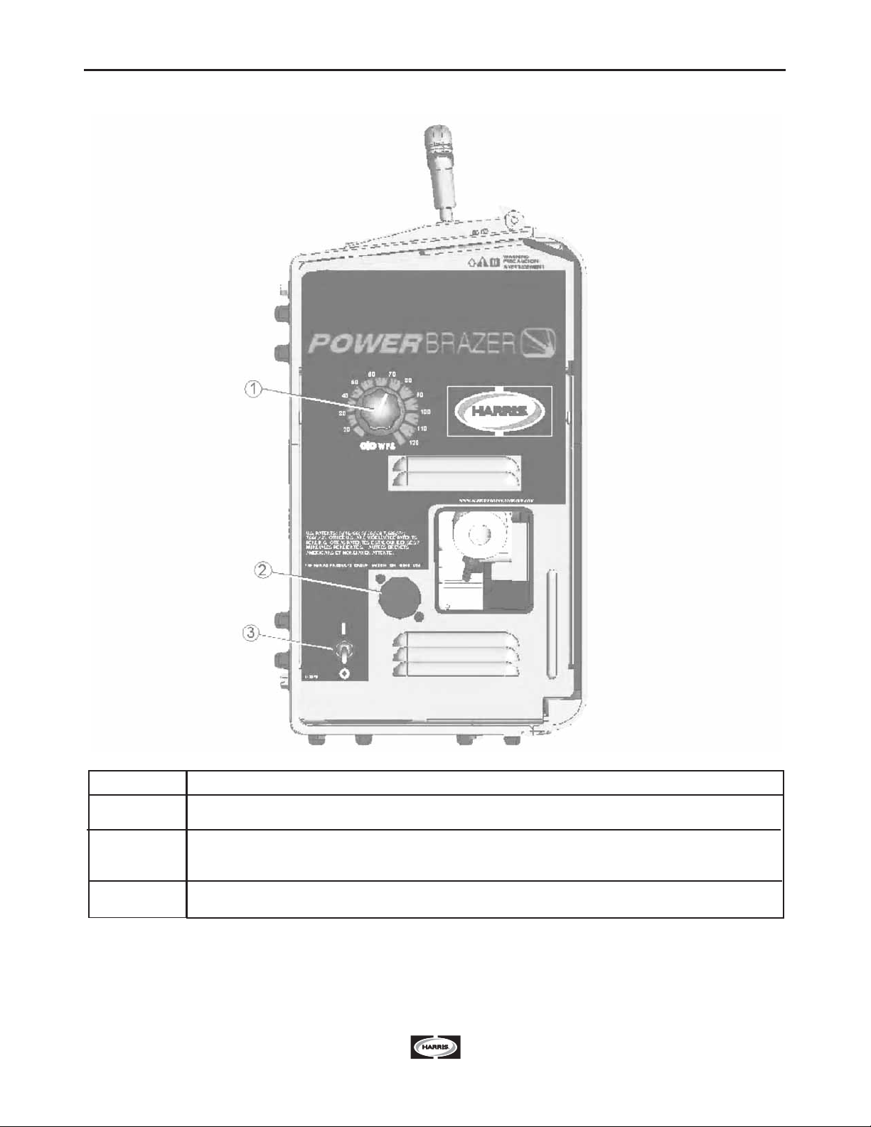
ITEM
1
2
3
DESCRIPTION
Wire Feed Speed Knob
5-pin gun trigger connector
Triggers on pins A and C
Power Switch
CASE FRONT CONTROLS
POWERBrazer

B-3 B-3
OPERATION
1
4
3
2
67
5
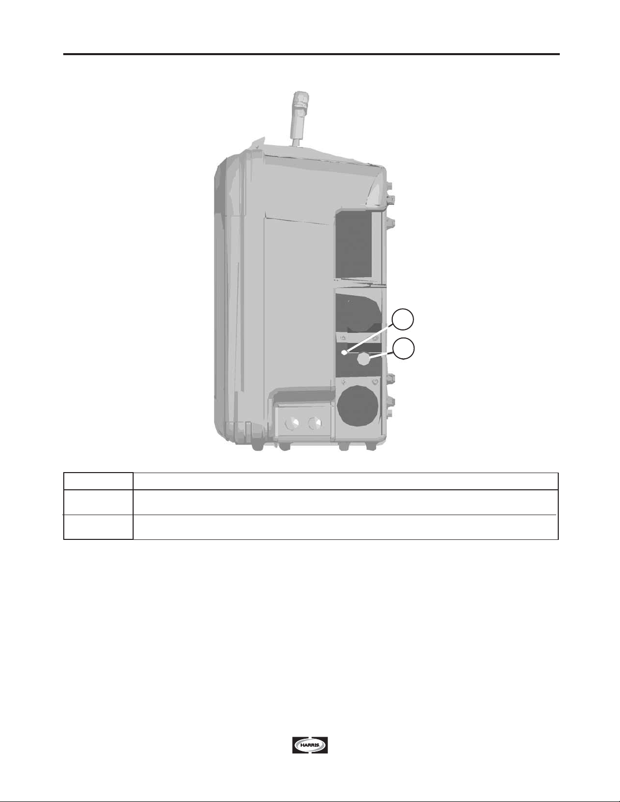
ITEM
1
2
3
4
5
6
7
DESCRIPTION
Pressure Adjustment Knob
Spool Retainer
Spindle Brake
Socket Head Cap Screw for Gun Bushing
Drive Hubs
Inlet Bushing
Cold Feed Pushbutton
PURPOSE
The pressure arm controls the amount of force the
drive rolls exert on the wire. Too much pressure
will distort the brazing wire. Too little pressure
allows the drive rolls to slip. Most brazing wires
feed best with the pressure arm set between 2
and 4.
Holds the spool in place. Remove by squeezing
the steel piece.
Used to set moderate friction to keep the spool
from unwinding.
Holds the gun in place.
Hold the drive hubs.
Guides the wire into the wire drive.
Used to jog the wire.
POWERBrazer
INTERNAL CONTROLS
B-4
B-4 OPERATION
POWERBrazer
REAR CONTROLS
ITEM
1
2
DESCRIPTION
Circuit Breaker
Power Cord
1
2

C-1
ACCESSORIES
PBKT-062
PBKT-094
PBGN-062
PBGN-094
1/16” gun, Drive Rolls and wire guides
3/32” gun, Drive Rolls and wire guides
1/16” gun
3/32” gun
KITS AVAILABLE
C-1
POWERBrazer

ELECTRIC SHOCK can kill.
• Only qualified personnel
should perform this installa-
tion.
• Only personnel that have read and under-
stood the POWERBrazer Operating Manual
should install and operate this equipment.
• The POWERBrazer must be plugged into a
receptacle which is grounded per any nation-
al, local or other applicable electrical codes.
• The POWERBrazer power switch is to be in
the OFF (“O”) position when connecting the
power cord to the input power.
--------------------------------------------------------------------
ROUTINE MAINTENANCE
• Check cords and the brazing gun for cuts and
damage.
• Clean and tighten all weld terminals.
PERIODIC MAINTENANCE
• Clean the drive rolls and inner wire guide and
replace if worn.
• Blow out or vacuum the inside of the feeder.
CALIBRATION SPECIFICATION
Wire Feed Speed Validation:
Calibration of the POWERBrazer may be required
when the printed circuit board, wire feed speed
potentiometer or motor is replaced or serviced.
Calibration matches the scale on the name plate to
the actual wire feed speed.
Tools required:
• RPM meter
• 7/16” open end wrench.
To verify if calibration is necessary:
1. Turn power OFF.
2. Set the wire feed speed to 100 in/min.
3. Remove the plastic cover from the lower portion
of the wire drive with a 7/16” wrench.
4. Turn power ON.
5. Measure the motor rpm when the COLD FEED
button is pressed.
6. Verify the rpm is within 16 – 19 rpm.
WARNING
SAFETY PRECAUTIONS
MAINTENANCE
To change the wire feed speed calibration:
(See Figure D.1)
Tools required:
• 5/16" nut driver
• RPM meter
• Shorting plug. The shorting plug shorts pins 4 and 8 of
connector J3 on the printed circuit board. J3 is an 8
pin molex connector.
1. Unplug the POWERBrazer.
2. Remove the (4) screws holding the rear cover inside
the feeder and remove the cover.
3. Open the idle arm.
4. Set the wire feed speed to 100 in/min.
5. Disconnect the fan connector from J3.
6. Plug in the POWERBrazer and turn power ON.
7. Insert the shorting plug into connector J3 on the print-
ed circuit board.
8. Remove the shorting plug.
9. Turn power OFF.
10. Reconnect the fan connector into J3.
11. Replace the cover and secure with the screws.
FIGURE D.1
D-1 D-1
POWERBrazer

TROUBLESHOOTING
If for any reason you do not understand the test procedures or are unable to perform the tests/repairs safely, contact your
Local Authorized Field Service Facility for technical troubleshooting assistance before you proceed.
CAUTION
This Troubleshooting Guide is provided to help you
locate and repair possible machine malfunctions.
Simply follow the three-step procedure listed below.
Step 1. LOCATE PROBLEM (SYMPTOM).
Look under the column labeled “PROBLEM (SYMP-
TOMS)”. This column describes possible symptoms
that the machine may exhibit. Find the listing that
best describes the symptom that the machine is
exhibiting.
Step 2. POSSIBLE CAUSE.
The second column labeled “POSSIBLE CAUSE” lists
the obvious external possibilities that may contribute
to the machine symptom.
Step 3. RECOMMENDED COURSE OF ACTION
This column provides a course of action for the
Possible Cause, generally it states to contact your
local Authorized Field Service Facility.
If you do not understand or are unable to perform the
Recommended Course of Action safely, contact your
local Authorized Field Service Facility.
HOW TO USE TROUBLESHOOTING GUIDE
Service and Repair should only be performed by Factory Trained Personnel. Unauthorized repairs
performed on this equipment may result in danger to the technician and machine operator and will
invalidate your factory warranty. For your safety and to avoid Electrical Shock, please observe all
safety notes and precautions detailed throughout this manual.
__________________________________________________________________________
WARNING
Observe all Safety Guidelines detailed throughout this manual
E-1 E-1
POWERBrazer

POWERBrazer
E-2 E-2
TROUBLESHOOTING
Observe all Safety Guidelines detailed throughout this manual
PROBLEMS
(SYMPTOMS)
POSSIBLE
CAUSE
RECOMMENDED
COURSE OF ACTION
The feeder does not power up: no
cold feed.
Inconsistent wire feeding or wire not
feeding but drive rolls turning.
The wire feed speed is fast (maxi-
mum) and there is no change when
the wire feed speed knob is adjust-
ed.
The POWERBrazer stops feeding
after a few seconds. After a while, it
will begin to feed again when it has
been retriggered.
1. The PowerBrazer is unplugged.
2. The power switch is turned off.
3. The circuit breaker tripped.
4. The motor is not receiving power.
1. The gun cable is kinked and/or
twisted.
2. The wire is jammed in the gun and
cable.
3. The gun liner is dirty or worn.
4. The filler wire is corroded or dirty.
5. Improper gun liner, tip, drive rolls
and/or inner wire guide.
6. Incorrect tension arm pressure on
the drive rolls.
7. The spindle brake is too tight.
8. Worn drive roll.
1. The tachometer is connected
improperly.
2. The tachometer has failed.
1. The motor has gone into thermal
overload.
1. Plug in the PowerBrazer.
2. Turn on the power switch.
3. Check cords for damage. Verify
the brazing wire easily feeds
through the gun. Consult a trained
repair person if the circuit breaker
repeatedly trips.
4. Consult a trained repair person.
1. Keep the gun cable as straight as
possible. Avoid sharp corners or
bends in the cable.
2. Remove the gun from the wire
feeder and pull the jammed wire
out of the gun and cable.
3. Blow dirt out of the liner with low
pressure (40psi or less). Replace
the liner if worn.
4. Use only clean electrode. Use
quality electrode from the Harris
Products Group.
5. Verify the proper parts are
installed.
6. Most filler wires feed well with the
pressure arm set between “2” and
“4”.
7. Verify the spool of wire moves
with minimal effort.
8. Replace the drive rolls if worn or
filled with dirt.
1. Verify all of the tachometer leads
are properly connected.
2. Replace the motor and tachome-
ter assembly.
1. Verify that the filler wire can be
easily pulled through the gun
when the pressure arm is open.
Output Problems
If for any reason you do not understand the test procedures or are unable to perform the tests/repairs safely, contact your
Local Authorized Field Service Facility for technical troubleshooting assistance before you proceed.
CAUTION
POWERBrazer
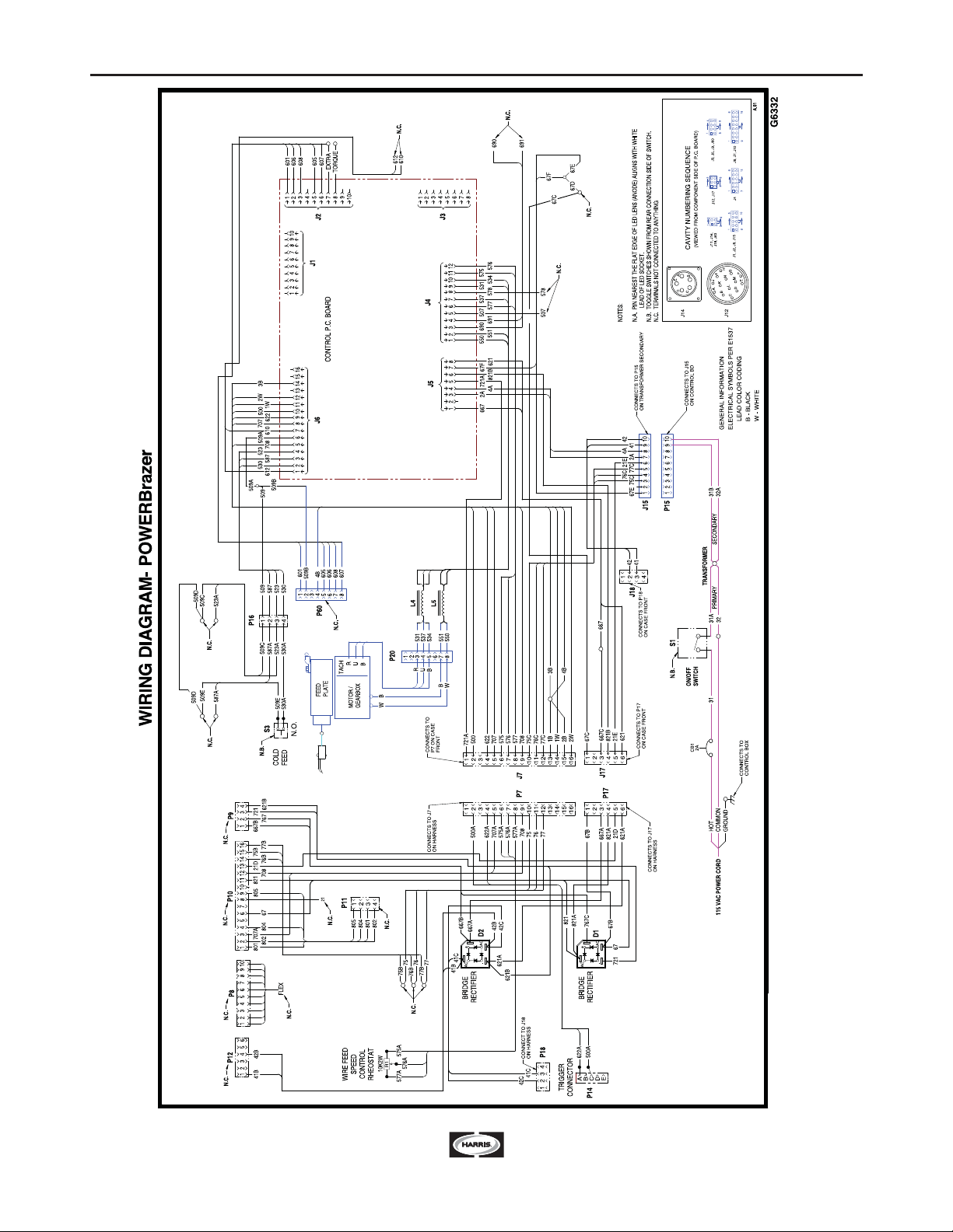
WIRING DIAGRAM F-1
F-1
NOTE: This diagram is for reference only. It may not be accurate for all machines covered by this manual. The specific diagram for a particular code is pasted inside the machine on
one of the enclosure panels. If the diagram is illegible, write to the Service Department for a replacement. Give the equipment code number.

DIMENSIONS
F-2 F-2
17.19
8.65
16” CIRCLE
12” x 18” ELLIPSE
23.17
14.81
POWERBrazer

POWERBrazer
NOTES
This manual suits for next models
1
Table of contents
Popular Soldering Gun manuals by other brands


QUICK INTELLIGENT EQUIPMENT
QUICK INTELLIGENT EQUIPMENT TS2300C Operation manual

Weller
Weller wsd 81 Operating instruction

Hakko Electronics
Hakko Electronics FM-202 instruction manual

STAMOS
STAMOS S-LS-1 user manual

Goot
Goot Anti-Static Series Owner's operation manual

Parkside
Parkside PLS 48 D2 Instructions for use


