QUICK INTELLIGENT EQUIPMENT TS2300C User manual

TS2300C
Lead Free Soldering Station
Operation Manual
Thank you for purchasing our Lead Free Soldering Station. It is designed for lead free soldering. Please read this
manual before operating the unit. Store this manual in a safe, easily accessible place for future reference.

1
Content
Ⅰ. Safety Instruction ................................................................................................................................................. 2
Ⅱ. Summary .............................................................................................................................................................. 3
Ⅲ. Feature ................................................................................................................................................................. 3
Ⅳ. Specifications ....................................................................................................................................................... 3
Ⅴ. Setting & Operating the Soldering Station .......................................................................................................... 4
5.1 Iron Holder and Sponge ............................................................................................................................... 4
5.2 Connection ................................................................................................................................................... 4
5.3Turn on/off .................................................................................................................................................... 4
5.4 Setting the Temperature ............................................................................................................................... 5
Ⅵ. Setting Working Parameters ................................................................................................................................ 6
6.1 Enter into SET menu.................................................................................................................................... 6
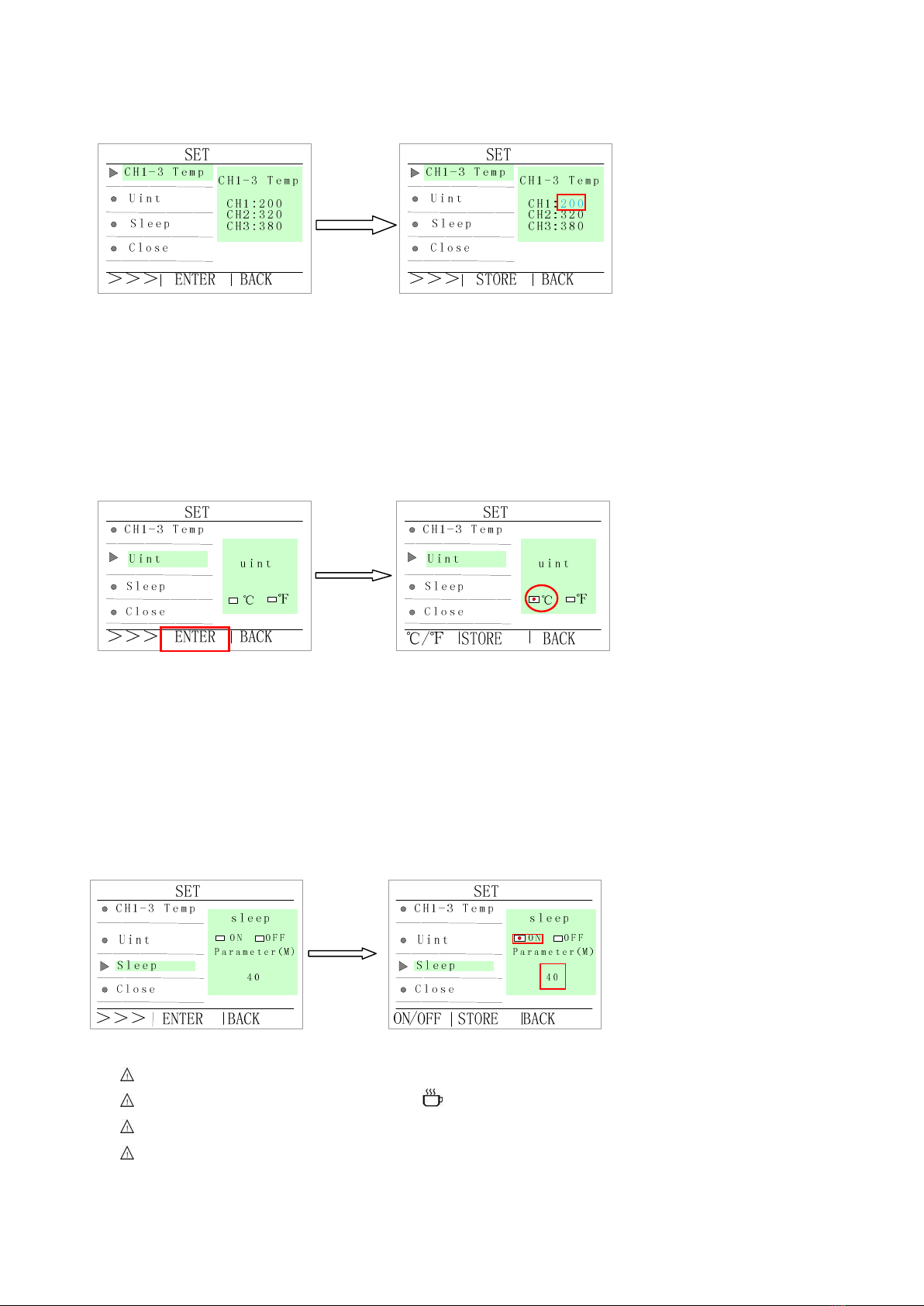
6.2 Temperature setting ...................................................................................................................................... 6
6.3 Temperature unit setting .............................................................................................................................. 7
6.4 Sleep time setting ......................................................................................................................................... 7
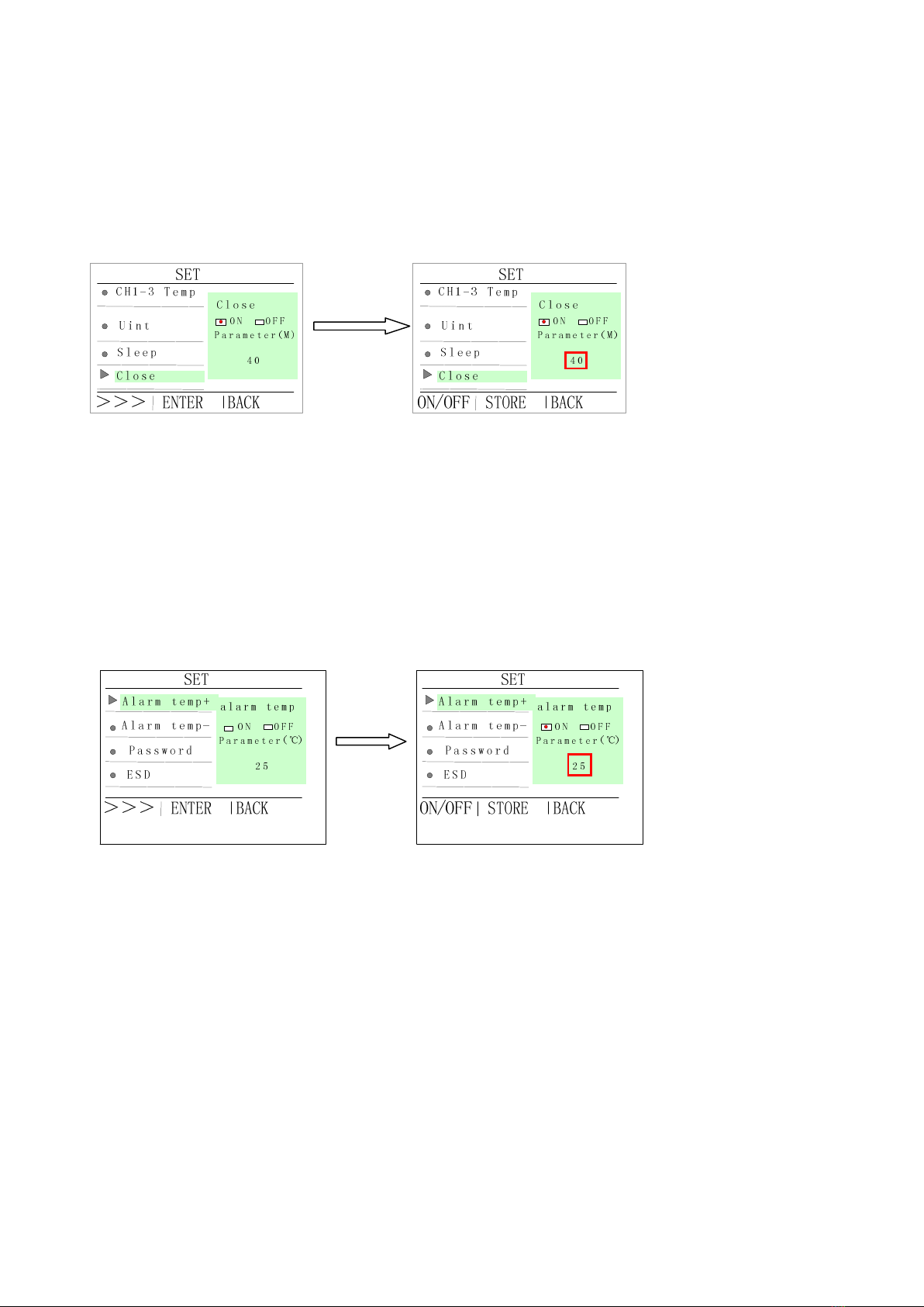
6.5 Close time setting ........................................................................................................................................ 8
6.6 Alarm temperature+ setting ......................................................................................................................... 8
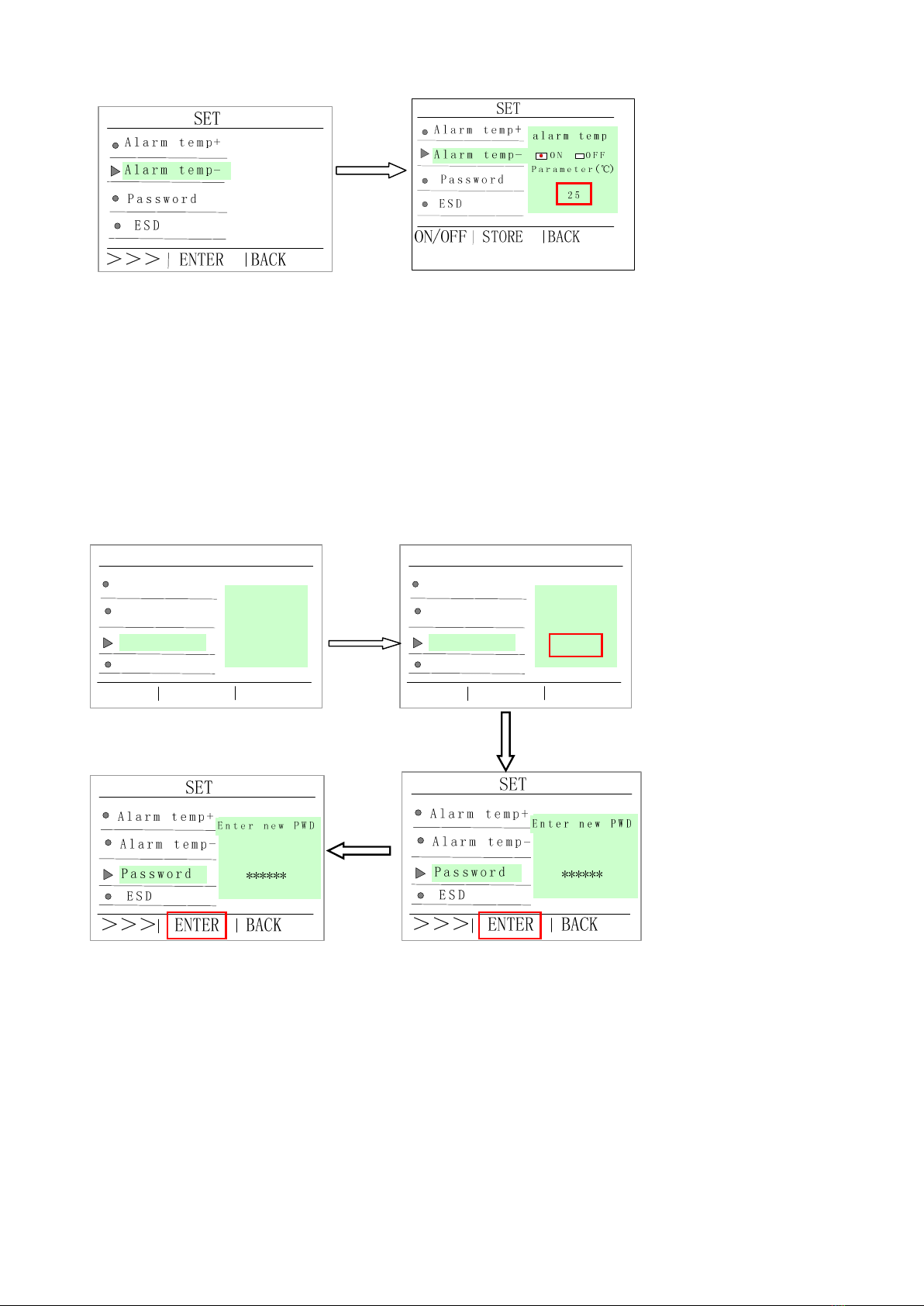
6.7 Alarm temperature- setting .......................................................................................................................... 8
6.8 Change password ......................................................................................................................................... 9
6.9 ESD .............................................................................................................................................................. 9
6.10 Key tone setting ....................................................................................................................................... 10
6.11 Address setting ......................................................................................................................................... 10
6.12Language setting ........................................................................................................................................11
Ⅶ.Calibrating the Temperature ................................................................................................................................11
Ⅷ、Tip Care and Maintenance ................................................................................................................................11
Ⅸ.Error messages .................................................................................................................................................... 13

2
Ⅰ. Safety Instruction
CAUTION
When the power is on, the tip’s temperature is very high. The mishandling may lead to burns or fire, be sure to
comply with the following precautions:
Please avoid an abuse of the unit and use the appliance only as the described manner.
Do not touch the metallic parts near the tip.
Do not use the product near flammable items.
Advise other people in the work area that the unit can reach a very high temperature and should be considered
potentially dangerous.
While replace parts or install tips, turn the power off and allow the unit to cool to room temperature.
To prevent damage to the unit and ensure a safe working environment, be sure to comply with the following
precautions:
Appliance shall only be used with rated voltage and frequency. (Refer to the trademark back of equipment.)
Don’t use the appliance if it is damaged, especially the supply cord.
This machine is equipped with a 3-wires grounding plug and must be plugged into a 3-terminal grounded
socket. Do not modify plug or use an ungrounded power socket. If an extension cord is necessary, use only a
3-wire extension cord that provides grounding.
Do not use the unit for other applications except soldering.
Only use genuine replacement parts.
Do not wet the unit. When your hands are wet, don’t use and disconnect the unit, or to pull the supply cord.
The soldering process will produce smoke, so make sure the area is well ventilated.
While using the unit, don’t do anything which may cause bodily harm or physical damage.

3
Ⅱ. Summary
The soldering station’s temperature adopts LCD double temperature display and digital calibration, shortcut
and convenience. The temperature induction is very exact and sensitive, the speed of heating and recovery of
temperature is very fast, and so it is the one of the most perfect tools for lead free soldering.
1. LCD display 2. Touch switch (Power: soft switching)
3. Mounting positioning edge 4. Handle socket
5. Power switch (Hard switching) 6. Power supply socket
7. ESD socket
Ⅲ. Feature
1. Can preset technological parameter of three channels, more practical.
2. Temperature alarm function, temperature unit can be changed (℃/℉).
3. Sensor preposition, real-time monitor temperature of tin, return temperature rapidly.
4. Solder tip change convenience.
5. Anti-static device, ESD measuring ability.
6. Have on-line communication function, can manage 99 machines at the same time.
Ⅳ. Specifications
Type TS2300C
Temperature displaying type LCD
Power consumption 150W
Working voltage 100~240VAC
Temperature Range 100℃~480℃/212℉~896℉
Room temperature to 320 ℃
time
8s
Ambient Temperature(Max) 40℃
Tip to Ground Resistance <2 Ω
1
2
3
4
5
6
7
Communication port

4
Tip to Ground Potential <2 mV
Dimension (W×H×D) 137×168×114mm
Weight 2 Kg
Suggestion thermometer is QUICK 191/192.
Ⅴ. Setting & Operating the Soldering Station
CAUTION: The supply voltage is consistent with the unit!
5.1 Iron Holder and Sponge
CAUTION:
The sponge is compressed. It will swell when moistened with water. Before using the station, moisten
the sponge with the water and squeeze it dry. Failure to do so may result in damage to the soldering tip.
If the sponge becomes dry during working, add appropriate water.
1. Dampen the cleaning sponge with water and then squeeze it dry.
2. Place it in groove of the iron holder base.
3. Add a little water to holder base. The sponge will absorb water to keep the sponge around it wet at all times.
5.2 Connection
CAUTION:
Be sure to turn off the power switch before connecting or disconnecting the soldering iron.
1. Connect handle cord to the handle socket (4).
2. Place the soldering iron into the iron holder.
3. Connect power plug to power supply socket (6).
4. Connect ESD socket (7).
5.3Turn on/off
1. Turn on the power switch (5).
2. Press and hold “POWER” button for 3s to enter main menu.
Soldering iron holder
Sponge
Holder base

5
Item
Figure Function
1 CH0 Header line (channel name)
2
Heater element status (ON/OFF)
3
Channel 1
Channel 2
Channel 3
4 Temperature symbol
5 200/320 Display channel 1/2 setting temperature
260 Channel 3 can be set two temperatures, “260”is the first setting temperature.
6 ℃ Temperature unit (℃/℉)
7
ESD line connection
Heater element heating
Reach the setting temperature
Heater element cooling
8 Unlock the station
9 350 Display real time temperature
5.4 Setting the Temperature
CAUTION:
Make sure the unit is logon (the default password is 000000) and the heater element is enabled, setting
temperature method:
1. The unit has three channels, press “1” button to select channel.
Press
POWER
1
2
3
4
5
6
7
8
9

6
2. Press and hold “1”button for 3s to enter CH1 menu, see picture:
3. Press and hold “3” button for 3s to enter CH3 menu, see picture
TIME:005S indicates keep first temperature (260℃) 5s.
Temperature setting
1) Press the “+” button once to increase the value by one digit, press and hold it to continuously
increase.
2) Press the “-” button once to decrease the value by one digit, press and hold it to continuously
decrease.
Ⅵ. Setting Working Parameters
6.1 Enter into SET menu
1. Press “2” and “3” buttons for 3s to enter into SET menu.
2. Press “1” (“+”) or “-” button to select menu.
3. Press “ENTER” button to enter selected menu, see picture.
6.2 Temperature setting
1. In the selected “CH1-3 Temp” menu, press “ENTER” button to Temperature Setting Menu.
2. Press “1” button to select channel.
Press“1”
3 seconds Setting temperature
Selected Temp menu
Press
“2” &“3”
Press
ENTER

7
3. Press “+” and “-” button to adjust the temperature value, see picture.
4. Press “STORE” to save the value and press “BACK” to return “CH1-3 Temp” menu.
6.3 Temperature unit setting
1. Press “ENTER” button to enter into “unit” Setting Menu.
2. Press “1” button to select temperature unit (℃or℉) .
3. Press “STORE” button to save the selection unit and press “BACK” to return unit menu, see picture.
6.4 Sleep time setting
1. Press “ENTER” button to enter into Setting Menu.
2. Press “1” button to select sleep status (“ON” or “OFF”).
3. Press “+” and “-”button to adjust sleeping time (The sleep time setting is effective in the “ON” status).
4. Press “STORE” button to save it and press “BACK” to return Sleep menu, see picture.
The soldering station enters into sleep state with a beep.
After entering the sleep state, the figure “ ” will be displayed and the LCD display screen will dim.
Note: The sleeping time range is 5s to 99 m, press any touch switch to activate station.
The sleep time is reached, the soldering station will power off automatically.
Press
Enter
Press
Enter
Setting menu
Press
ENTER
Selected ℃
CH1-3 Temp menu
Setting menu
Unit menu
Sleep menu Setting menu

8
6.5 Close time setting
1. Press “ENTER” button to enter into Setting Menu.
2. Press “1” button to select close mode (“ON” or “OFF”).
3. Press “+” and “-”button to adjust close time (The close time setting is effective in the “ON” status).
5. Press “STORE” button to save it and press “BACK” to return Close menu, see picture.
Note: The close time setting range is 1-240min.
6.6 Alarm temperature+ setting
1. Press “ENTER” button to enter into Setting Menu.
2. Press “1” button to select status (ON or OFF).
3. Press “+” and “-”button to adjust value (The alarm temperature setting is effective in the “ON” status).
4. Press “STORE” button to save it and press “BACK” button to return Alarm+ menu, see picture.
Note: The alarm temperature + setting range is 2-99℃.
6.7 Alarm temperature- setting
1. Press “ENTER” button to enter into Setting Menu.
2. Press “1” button to select mode (ON or OFF).
3. Press “+” and “-”button to adjust alarm temperature value (The alarm temperature- setting is effective in the
“ON” status).
4. Press “STORE” button to save it and press “BACK” button to return Alarm- menu, see picture.
Press
ENTER
Press
ENTER
Close menu Setting menu
Alarm + menu
Setting menu

9
Note: The alarm temperature - setting range is 2-99℃.
6.8 Change password
1. Press “ENTER” to enter password menu and enter the default password 000000(Press “+” and “-”button to
adjust password value and press “1” to move the cursor to the next digital).
2. Press “ENTER” button to confirm it.
3. Enter the new password two times.
4. Press “ENTER” button to save it, see picture
**
>>> ENTER BACK
SET
******
Password
Password
Alarm temp-
E S D
Alarm temp+
**
>>> ENTER BACK
SET
******
Password
Password
Alarm temp-
E S D
Alarm temp+
6.9 ESD
1. Press “ENTER” button to enter ESD menu.
2. Press “1” button to select mode (ON or OFF).
3. Press “STORE” button to save it and press “BACK” to return ESD menu, see picture.
Press
ENTER
Press
ENTER
Press “ENTER”
Press
ENTER
Alarm - menu
Setting menu

10
6.10 Key tone setting
1. Press “ENTER” button to enter into Key tone menu.
2. Press “1” button to select sound mode (ON or OFF).
3. Press “STORE” button to save it and press “BACK” to return Key tone menu, see picture.
6.11 Address setting
1. Press “ENTER” to enter password menu and enter the default password 865637(Press “+” and “-”button to
adjust password value and press “1” to move the cursor to the next digital).
2. Press “ENTER” button to confirm it.
3. Enter the new address (1-99).
4. Press “ENTER” button to save it, see picture
Press
ENTER
Press
ENTER
ESD menu Setting menu
Key tone menu Setting menu
Press “ENTER”
Press
ENTER

11
6.12Language setting
1. Press “ENTER” button to enter Setting menu.
2. Press “1” button to select language (English/S-Chinese / T-Chinese).
3. Press “STORE” button to save it and press “BACK” to return Language menu, see picture.
Ⅶ.Calibrating the Temperature
The soldering iron should be recalibrated after changing the iron.
Tool: QUICK 191/192 thermometer
Method: 1.Press and hold “1” and “3” buttons at the same time to enter into calibration menu.
2. The LCD display is flashing, press “+” and “-” button to enter value.
3. When the value is the same as the thermometer, press “Enter” to calibrate it.
Ⅷ、Tip Care and Maintenance
Select Tip
Press
ENTER
Language menu Setting menu

12
1. Select a tip that maximizes contact area between the tip and solder joint. Maximizing contact area gives the
most efficient heat transfer, allowing operators to produce high quality solder joints quickly.
2. Select a tip that allows good access to the solder joint. Shorter tip lengths allow more precise control. Longer
or angled may be needed for soldering densely populated boards.
3. Tip type
Soldering tip maintenance
1) High temperature would affect/decrease the lifetime of soldering tip. Set the temperature as per
application but as low as possible.
2) The oxide and carbide produced by residual flux will damage the soldering tip, like soldering
deviation and slow heat conduction etc. Clean the soldering tip regularly (every week for long time
continuous using).

13
3) Under high temperature, the solder in tip will produce oxide, which will damage its heat
conduction. Turn off the heating controller when not use.
Prolong the lifetime of soldering tip
1) Coat the soldering tip with solder to prevent oxide.
2) Set the temperature as per application but as low as possible.
3) Choose the right type of soldering tip.
4) The plating would be broken if the tip is bent. Do not use the soldering tip as a detecting tool.
5) Activated rosin will corrode the tip plating. Choose the solder wire with less activated rosin.
6) Do not press the soldering tip. Much pressure is not helpful for heat conduction. Melt the solder
wire to create a solder bridge between tip and point, to speed up heat transfer.
Ⅸ.Error messages
Various error messages will be displayed when there is something wrong with the unit.
“Sensor broken”: sensor open a way
“Handle type”: handle type wrong
“NO handle ”:handle is not insert
“sensor shorten”:sensor short circuit
“Heater broken”:heater element open a way (Tip low temperature alarm)

14
QUICK INTELLIGENT EQUIPMENT CO., LTD.
ADD: NO.11, FengXiang Road, Wujin High-Tech Industrial Development Zone, Jiangsu,
China
TEL: 86-519-86225678
FAX: 86-519-86558599
POSTCODE: 213167
WEBSITE: www.quick-global.com
Table of contents