TAIYO ELECTRIC
IND.CO.LTD.
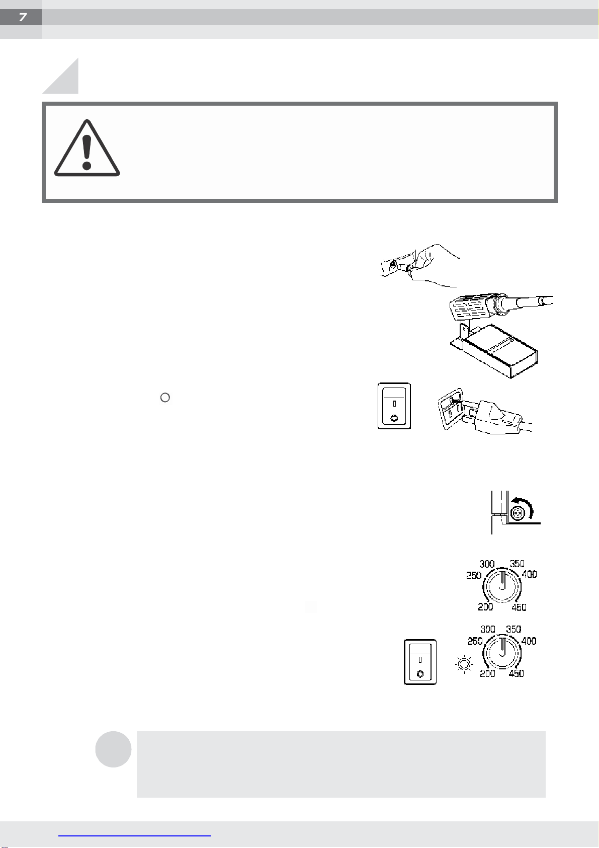
B. RX-711 series only
B-1. Set the temperature display changeover switch on the left side of
the front panel to the SET side. With the switch at this position, th
e
temperature
display
shows
t
he
set
temperature.
B-2. Set the power switch to ON (the I mark side).
The heater monitor lamp will light and the heater will
start to heat up. When turning the soldering station
power switch ON from OFF, “999” will be initially
displayedfor approximately 10 seconds.
B-3. Set the required temperature by using the
temper-
ature setting knob.
B-4. After doing the setting, when changing the switch to
t
h
e
MEAS side the digital display will show the measured
tempera-
ture. When the heater temperature reaches the set
temperature,
the monitor lamp will flash. This indicates that the soldering unit
is ready for use.
When turning the soldering station power ON again after
turnin
g
it OFF within one hour, the temperature displayedwill lower
to
“000” and then will displaymeasured
temperature.
CAUTION
Do not turn the temperature setting knob beyond 480°C. By
turning the temperature setting knob clockwise toward "MAX.",
the required temperature and tip temperature can be set
beyond 480°C. It may go up to approx. 510°C. Setting beyond
500°C could result in damage to your soldering station.
NOTE
1
NOTE
2
NOTE
3
There may be a difference of 2°C between the SET and MEAS temperature
display.
When the
soldering station
is
shipped
the
temperature calibration
is done with the
temperature display
set on the
SET side.
With the
temperature
display
set on the MEAS side
correction
of the tip
temperature
by
using
the
temperature setting knob is not
required.
When
the
temperature display
is set on
MEAS,
the
temperature displayed
will
fluctuate from
2 to 3
degrees
Celsius.
When the
temperature display
is set on MEAS if a heat load is placed for 10
seconds,
the
temperature display will not
change.
Example
While contacting
the tip on a wet
sponge,
the actual tip t
em
-
perature will drop for 10
seconds.
However the temperature shown on the
display will
be the
one before
the tip was
touched on
the sponge.
The actual temperature will be shown on the
display
10
seconds
later. The
temperature control circuit works
to
recover
the set
temperature when
the tip
is cooled
immediately
even thoughthe
display
of measured temperature is
not
changed.