Harrison Hydra-Gen HU507-GB12 Product manual

1
Harrison Hydra-Gen Ltd.
Hydraulic Driven AC Generator System
Installation and Maintenance Guide
For Harrison Hydra-gen Model:
HYDRA-DRIVE
HU507-GB12
(12-28-16) - Spec. B
For technical assistance contact:
Harrison Hydra-Gen Ltd.
14233 West Rd.
Houston, Texas 77041
(281) 807-4420 Ph.
(800) 723-3334 Toll
(281) 807-4815 Fax
www.harrisonhydragen.com
2
GENERAL INFORMATION
The Hydra-Drive is a gearbox designed to make it possible to put a variable displacement pump
on a Ford 4 x 4 truck with the TorqShift 6 transmission. The gear box attaches to a Chelsea 249
PTO output lowering it 8” and converting the output to a SAE-B 2 bolt. The Hydra-Drive is a 1:1
gearbox so the PTO ratio of 124% is not changed. The direction of rotation does change from
opposite engine to engine rotation. The pump rotation needed is clockwise rotation.
IMPORTANT: Read this manual before proceeding in the installation of the Hydra-Drive.
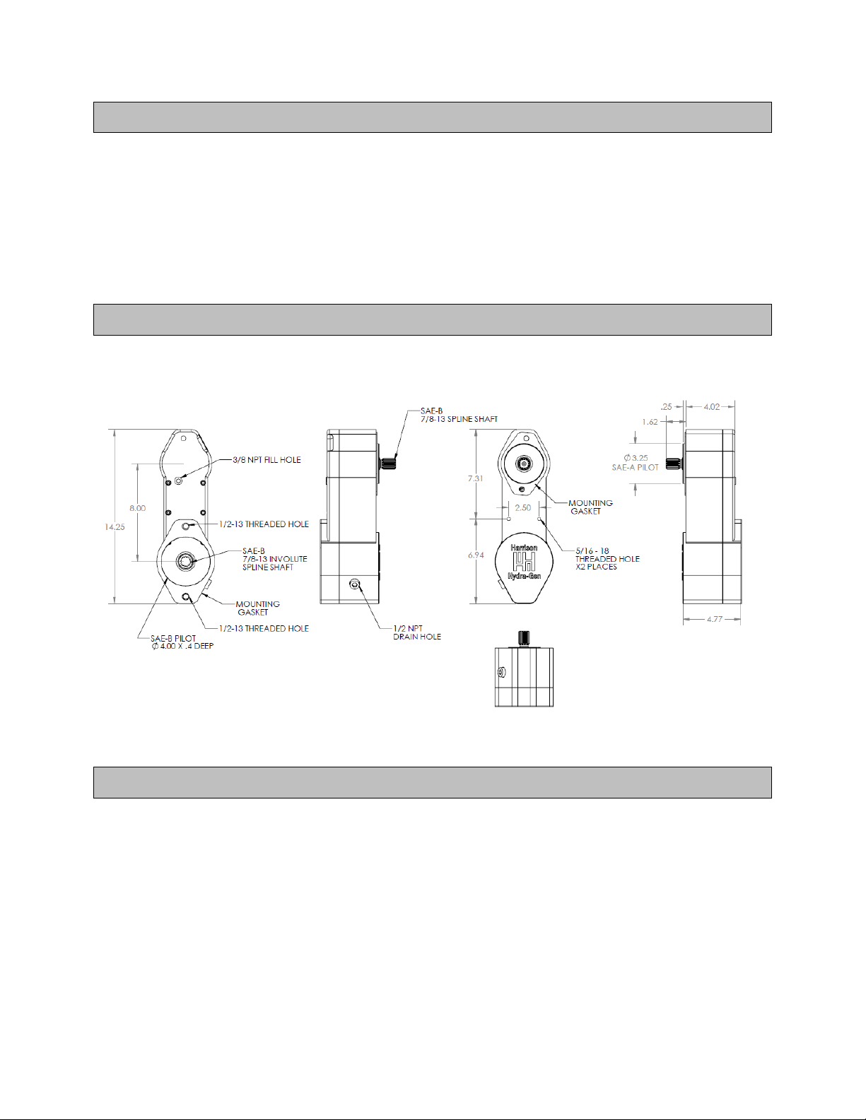
DIMENSIONS
SPECIFICATIONS
Ratio: 1:1
Input: SAE-A pilot with a SAE-B 7/8-13 tooth shaft
Output: SAE-B pilot with a SAE-B 7/8-13 tooth spline
Output Rotation: Engine (Clockwise pump rotation needed)
PTO required: Chelsea #249 FMLLX-B4XP (124% ratio)
3
INSTALLATION
Before installing the PTO, Hydra-Drive and Pump, make sure the area around the transmission
is clean. Do to the fact that one on the mounting bolts to mount the Hydra-Drive to the PTO is
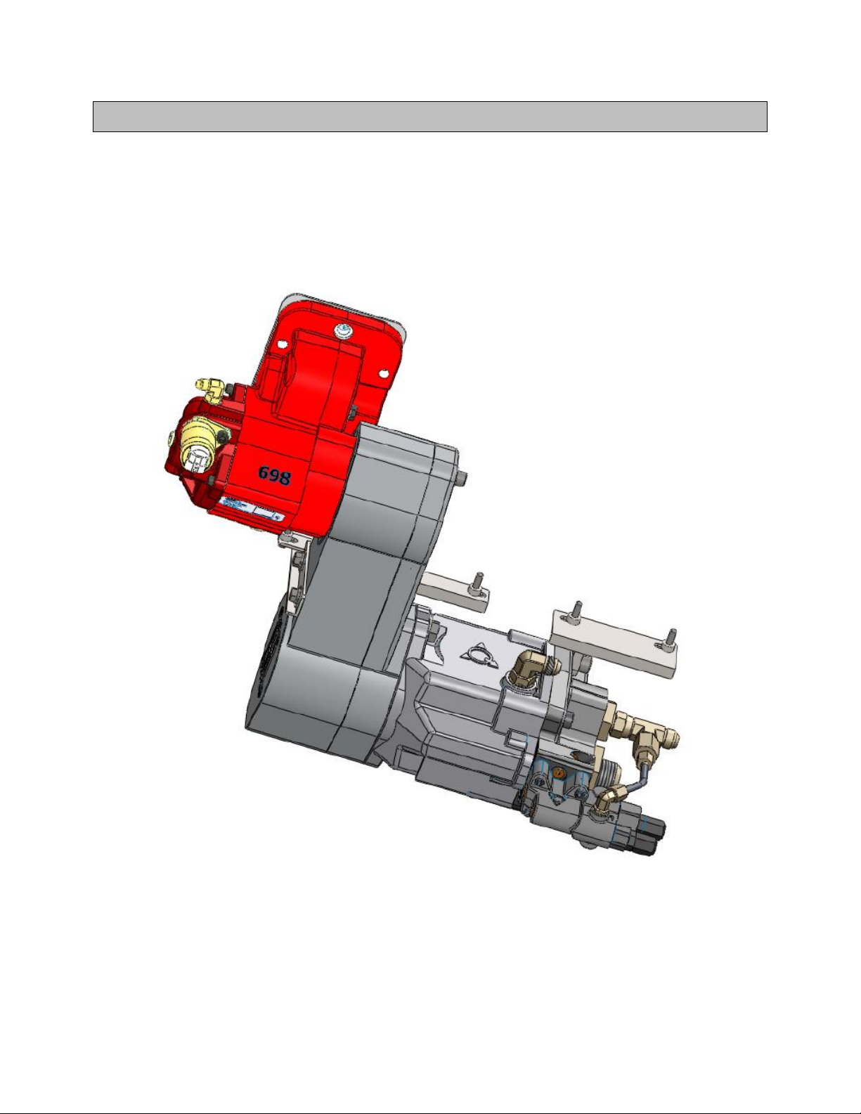
behind one of the gears, it will require assembling the Hydra-drive under the truck. Figure1
below shows the assembly.
Figure 1
4
STEP 1
1. Remove the 4X4 drive shaft. This will make it easier to install the PTO, Hydra-Drive and
Pump.
2. Install the Chelsea PTO to the transmission. (Refer to the Chelsea Manual for
instructions)
3. Test the PTO for correct operation before installing the Hydra-Drive.
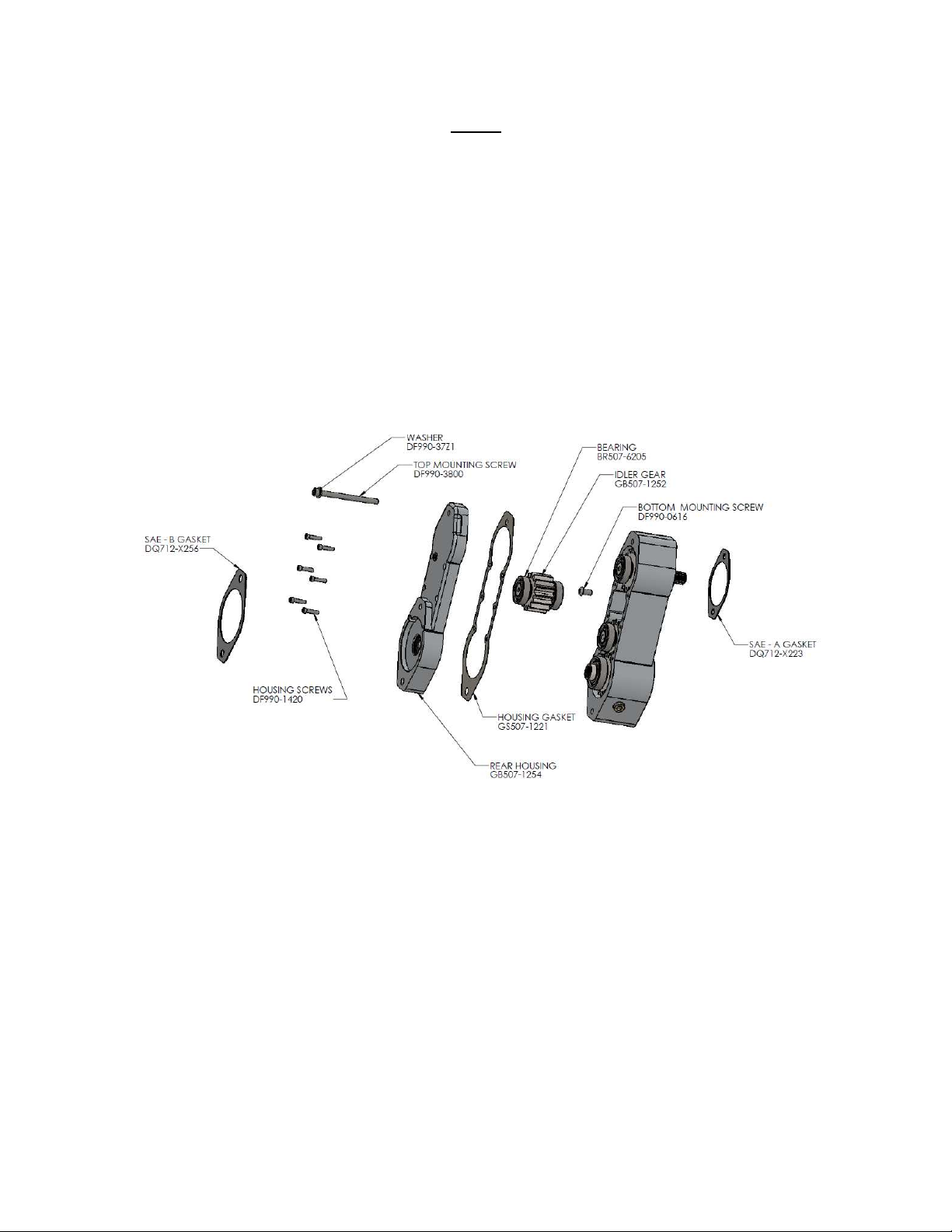
The Hydra-Drive is shipped pre-assembled from the factory. Start by separating the housings
and remove the top idler gear to get to the bottom SAE-A mounting hole. See figure 2 below.
Figure 2

5
STEP 2
1. Refer to figure 2 above for step 2 instructions.
2. Set the Hydra-drive on a clean surface. Remove the 6 bolts # DF990-1420 holding the 2
housings together.
3. Turn the Hydra-drive on the side. Using a rubber hammer lightly tap around the side of
the rear cover as you pull it out. Do not use a screwdriver to pry the housings apart. This
could damage the seal surfaces and will cause it to leak. Light tapping and slightly
wiggling in housings is all you should need to separate them.
4. Remove the top idler gear. The bearings are pressed on to the gear. Slightly move the
gear side to side while pulling up should be all it takes to remove the gear and bearings
from the housing. It is not necessary to remove any of the other gears.
5. With the gear removed from the housing the bottom hole to mount the assembly to the
PTO is visible.
6. Using half of the spline grease supplied by Chelsea (#379688) coat the female spline of
the PTO shaft. Make sure to coat all the roots and valleys of the splines. The other half
will be used to coat the female splines of the Hydra-Drive.
7. Using the SAE-A gasket # DQ712-X223 and the button head screw # DF990-0616, install
the assembly to the PTO. Installing the top screw # DF990-3800 in temporary will help
the line up and make this easier to line up and mount. Install the button head screw into
the bottom hole and tighten to 30 ft. lbs.
8. Remove the top screw.
9. Install the idle gear back into the housing. Make sure all the gears are set in position.
10. Install the washer #DF990-37Z1 to the top screw # DF990-3800 and the 6 housing
screws # DF990-1420 into the rear housing # GB507-1254. Install the gasket on to the
rear housing. Having the screws in place should hold the gasket in place. Install this
group to the main housing group. Slowly slide the housing over the bearings and with
slight side to side movement with pushing them together should be all it takes to mate
the parts together. Light tapping with a rubber hammer may be used if needed. Make
sure the gasket stays in place. Watch as the seal goes over the shaft and does not get
damaged. As the two housing get close to mating line up the gasket and start the
screws. This will keep the gasket in place.
11. After the housing are mated together tighten the 6 screws # DF990-1420 to 8-10 ft. lbs.
and the tops screw DF990-3800 to 30 ft. lbs.
Table of contents


