Hartenberger mega compact User manual

Instructions for use
Hartenberger
Underwater Hand Lamp
mega compact
mega compact D2

Hartenberger Underwater Lamp mega compact / mega compact D2 Instructions for use
2
CONTENTS
SAFETY WARNING. ............................................................................... 2
GUARANTEE. ....................................................................................... 2
APPLICATIONS...................................................................................... 2
ARTICLE DESCRIPTION. ......................................................................... 3
TECHNICAL SPECIFICATIONS. ................................................................. 4
REAR SCREW FITTING. ......................................................................... 5
POWER PACK ...................................................................................... 5
PREPARATION FOR USE......................................................................... 6
USING THE UNDERWATER LAMP............................................................. 7
AFTER USE. ......................................................................................... 8
TRANSPORT......................................................................................... 8
STORAGE. ........................................................................................... 9
CHARGING........................................................................................... 9
CARE AND MAINTENANCE.................................................................... 13
SERVICE............................................................................................ 13
FAULT DIAGNOSIS. ............................................................................. 14
ACCESSORIES.................................................................................... 15
SPARE PARTS.................................................................................... 15
SAFETY WARNING
Before attempting to use the underwater lamp, carefully read and
adhere to these instructions for use.
Before the first time the lamp is used, the lamp must be charged.
Do not operate the lamp immediately after charging.
Always point the beam of the lamp away from yourself.
Never point the lamp beam in the direction of another person.
GUARANTEE
When these instructions for use and the care and maintenance
guidelines are adhered to, we will guarantee all mechanical parts made
from steel, aluminium, glass and plastic for a period of 5 years against
manufacturers defects and material failure. All electronic parts are
guaranteed for a period of 2 years. The rechargeable cells have a
guarantee against manufacturers defects and material failure for 6
months.
If the accumulators are dealt with and handled correctly, (see page 11),
they are covered by our 2 year guarantee.
Halogen bulbs and O-Ring seals are expendable items and are
therefore not covered by the guarantee.
Any unauthorised work on the lamp, i.e. the removal or tightening of
screws, or the removal of the guarantee seals, will make the guarantee
invalid.
APPLICATIONS
The maxi compact underwater lamps are for use in underwater lighting
applications. Use of the lamp in an environment other than fully
submerged in water may cause the rechargeable cells to overheat
which may result in the expected life of the cells being shortened.

Hartenberger Underwater Lamp mega compact / mega compact D2 Instructions for use
3
ARTICLE DESCRIPTION
SIDE VIEW, EXTERNAL
1. Front Seal
2. Housing/Body
3. Rear Screw Fitting
4. Button pad – (minus)
5. Cover screw
6. Transport lock
7. LCD Display
8. Button pad + (plus)
1 2 3 Diagram 1 4 5 6 7 8 Diagram 2
FRONT SEAL
The front glass plate with the O-Ring is pressed into the housing during
the assembly by the manufacturer. It can only be opened by an
authorised workshop.
HOUSING / BODY (MEGA UND MEGA D2)
The housing / body is sealed with the glass plate and the rear screw
fitting.
REAR SCREW FITTING
The rear screw fitting must be unscrewed to access the rechargeable
cell pack for charging and/or to replace the halogen bulb.
BUTTON PAD (SWITCHES + AND -)
The – (left) and + (right) switches select all the electronic controls and
features.
COVER SCREW
The 4 cross head cover screws serve to secure the rear cover, the two
switches and the transport lock.
TRANSPORT LOCK
With the transport lock positioned to the right in the lock position, the +
switch is deactivated preventing inadvertent use or activation.
LCD DISPLAY
The LCD display shows the current programme mode, the state of
charge of the cells, the current power setting and the resulting
remaining burn time.
The serial number, date of manufacture and more can also be viewed
in the LCD Display.

Hartenberger Underwater Lamp mega compact / mega compact D2 Instructions for use
4
POWER PACK MEGA
1. Halogen Bulb
2. Reflektor
3. O-Ring
4. Charging Socket
5. Cell Pack
6. Plug-In Connection
1 2 3 4 5 6 Diagram 3
POWER PACK MEGA D2
1. D2 Gas discharge xenon lamp
2. Reflektor
3. O-Ring
4. Gas Discharge Elektronic
5. Charging Socket
6. Cell Pack
7. Plug-In Connection
1 2 3 4 5 6 7 Diagram 4
HALOGEN BULB
The halogen bulb is pushed into a standard socket (Type 6.35) and can
easily be replaced.
D2 GAS DISCHARGE XENON BULB
Curves of light as opposed to a glowing bulb produce a particularly
efficient source of light.
REFLECTOR MODULE
The reflector module is located on the power pack or the gas discharge
module.
Flood for video
Spot for illumination
GAS DISCHARGE ELECTRONICS
Electronic module provides the necessary power conversion for gas
discharge applications.
CHARGING SOCKET
The plug from the charger is plugged into the charging socket for
charging purposes.
CELL PACK
The cell pack is a plug in unit and can be replaced within seconds with
a second unit.
PLUG-IN CONNECTION
The Plug in connection serves as an electrical and mechanical
connection between the power pack and the electronic control panel.

Hartenberger Underwater Lamp mega compact / mega compact D2 Instructions for use
5
TECHNICAL SPECIFICATIONS
APPROX. BURN TIME INCL. WARNING BLINKS IN MINUTES WITH NMH CELL PACK 14.4V / 4,5AH
Halogen Bulb 30W 50W 100W* D2 35W**
Time of use at 25% setting 390 Min. 260 Min. 120 Min.
Time of use at 50% setting 210 Min. 130 Min. 60 Min.
Time of use at 75% setting 150 Min. 95 Min. 40 Min. 90 Min.
Time of use at 100% setting 110 Min. 65 Min. 30 Min. 70 Min.
Time of use at 125% setting 80 Min. 48 Min. 22 Min.
The Heavily printed figures represent the burn times with the standard bulbs as delivered
Warning ! *The nickel metal hydride cells are on the limit of their capabilities
when used with a 100 watt halogen bulb. A reduced life
expectancy can be expected.
**D2 Gas discharge bulb 35 W; the electronic module uses approx.
43 Watts. The illumination is equivalent to a 100 Watt halogen bulb.
The burn time of a lamp is dependant upon water temperature,
state of cell charge and the type of bulb.
• New NMH Cells only reach their full capacity after 2-3 charging cycles.
• The water temperature greatly affects the burn time. For example, in
water temperatures of between 4 and 6 °C, (40 - 45 °F) the burn time
will be at best 90% of the stated capacity.
• Halogen bulbs available in retail outlets often need up to 10% more
power as stated. The stated burn times will therefore be shortened.
DIMENSIONS/WEIGHT/PRESSURE PROOF
Length & Diameter approx. weight on
land
approx. weight in water Resistance to water
pressure
mega 185mm x 89mm
7” x 3½”
1.6 kg
3 lbs 8 oz
0.4kg
14 oz.
100m
330 ft
mega D2 235mm x 89mm
10” x 3½”
1.9kg
4 lbs 10 oz.
0.4kg
14 oz.
100m
330 ft
FRONT GLASS PLATE
The mega compact lamps have a tempered borosilicat-glass plate as
standard. This glass plate has a temperature shock resistance of 300°C
(570°F). It is therefore possible to use the lamps above and under
water. A rapid cooling of a heated front glass is no problem.

Hartenberger Underwater Lamp mega compact / mega compact D2 Instructions for use
6
REAR SCREW FITTING
OPENING THE SCREW FITTING
The housing is opened by unscrewing the fitting anti-clockwise, (thread
length approx. 10 mm [3/8“]). Whilst opening the housing, it should be
held in an upright position, thus preventing the power pack from
inadvertently falling out.
CLOSING THE HOUSING
Before closing the housing, all threads, sealing surfaces and seals
must be checked for integrity and cleanliness.
Should the sealing surfaces and/or components be contaminated, then
the O-Rings and its groove should be thoroughly cleaned. Should the
sealing surfaces and/or components be damaged, then all damaged
parts should be replaced. If the O-Ring is removed, care must be taken
not to damage the groove in which the O-Ring sits. A soft blunt tool
should be used for the removal of the O-Ring, i.e. a wooden tooth pick.
Before the components are refitted it is recommended that a thin
coating of silicone grease is applied as lubrication. It is recommended
that after such work has been carried out, that the seal/integrity of the
housing is first checked underwater without the power pack fitted. The
housing is then closed by screwing the components clockwise together.
The screw fitting should be tightened by hand only until the parts are
mated together.
POWER PACK
REMOVAL OF THE POWER PACK
The power pack consists of the cell pack and the reflector.
After unscrewing the housing from the rear screw fitting, the power pack
can then be unplugged by simply pulling it away from the rear screw
fitting. The 4 pins serve as a mechanical and electrical connection for
the components.
Warning ! When using the gas discharge technology, first remove the gas
discharge module from the power pack before removing the cell
pack from the electronics. The assembly is the reverse procedure.
REFITTING THE POWER PACK
Hold the rear screw fitting with the pins pointing upwards. The power
pack can then be plugged onto the fitting. Make sure that the locating
pin (located next to one of the connecting pins), will be correctly located
in the orifice of the power pack base. This ensures that the power pack
cannot be incorrectly connected.
REFLECTOR MODULE
The reflector module can simply be pulled off the front end of the power
pack (or gas discharge module). Caution must be taken to ensure that
the reflector unit is not removed skrew. This may result in damage to
the halogen or gas discharge bulb. The 2 O Rings located on the
reflector module can be used as spare o Rings for the housing (68mm x
3.0 mm and 68mm x 2.0mm).
POWER PACK
On the front end of the power pack there are 3 contacts pins located for
the plug on gas discharge module, the socket for the halogen bulb and

Hartenberger Underwater Lamp mega compact / mega compact D2 Instructions for use
7
two stowage housings for spare halogen bulbs. The charging socket is
located behind an opening on the outside of the power pack. On the
rear side of the power pack are the 4 contact plugs for the electronic
module.
SPARE HALOGEN BULB(S)
Under the reflector module in the front of the power pack there are two
stowage housings for spare halogen bulbs. These are accessed by
turning open the heat protector shield.
Warning ! After using the lamp, the heat protection shield remains hot for
some time after the lamp has been turned off.
The lamp should never be operated without the heat protector
shield in the correct position.
PREPARATION FOR USE
BEFORE THE LAMP IS USED FOR THE FIRST TIME
Before the first use, the cells must be charged (See page 12)
Hartenberger underwater lamps are manufactured to a high degree
of precision and each lamp is tested to a water pressure of 10
bars. The condition of the lamp and in particular the housing and
sealing rings should however be checked before the first use (See
page 5).
Warning ! Due to damage during transportation or hidden material defects,
leakage can occur (not the fault of the manufacturer). To check if
the housing is pressure tight, the first dive should be carried out
without the housing insert, i.e. empty.
BEFORE EACH USE
The rechargeable NMH cells will slowly discharge naturally when not in
use, (depending on the ambient temperature up to 60% discharge in
one month!). We recommend therefore that the cells are charged one
day before each use.
Before each use, the front threads, sealing surfaces and O-Ring must
be checked for integrity and cleanliness. (See Closing the housing
Page 6).
If the bulb has been removed for transport, it should be refitted into the
socket.
Refit the halogen bulb in the socket or the gas discharge module in the
sockets, which may have been removed for transportation.
Only release the transport lock to the unlocked position
immediately before use. (See page 13).
USING THE UNDERWATER LAMP
SWITCH UNIT / PROGRAMME MODE
The switch electronics and the power pack are both controlled by
microprocessors. This provides a large range of features and functions.
A large emphasis has been placed on simply, user-friendly intuitive
operation.
The entire electronics are controlled via two switches, left minus (-) and
right plus (+).

Hartenberger Underwater Lamp mega compact / mega compact D2 Instructions for use
8
To operate the lamp, individual preferences can be selected in different
programmes (except for use with D2 gas discharge module).
The programme set appears in the top right hand corned of the display
when both switches are pressed simultaneously. (A,B,C, or T).
If both switches (+/-) remain pressed, the programme will change
approx. every 3 seconds to the next programme,
(A,B,C,T,A,B,C,T,...). Releasing the switches will store the last
displayed programme in the power pack. After replacing a power
pack, the stored programme will be activated.
Programme A Lamp only ON/OFF
Programme B Lamp dimmer in 5 stages of 25% from 25% to 125%.
Programme C Lamp dimmer infinitely variable in 5% steps from 25% to 125%.
Programme T Lamp is only ON as long as the switches are pressed.
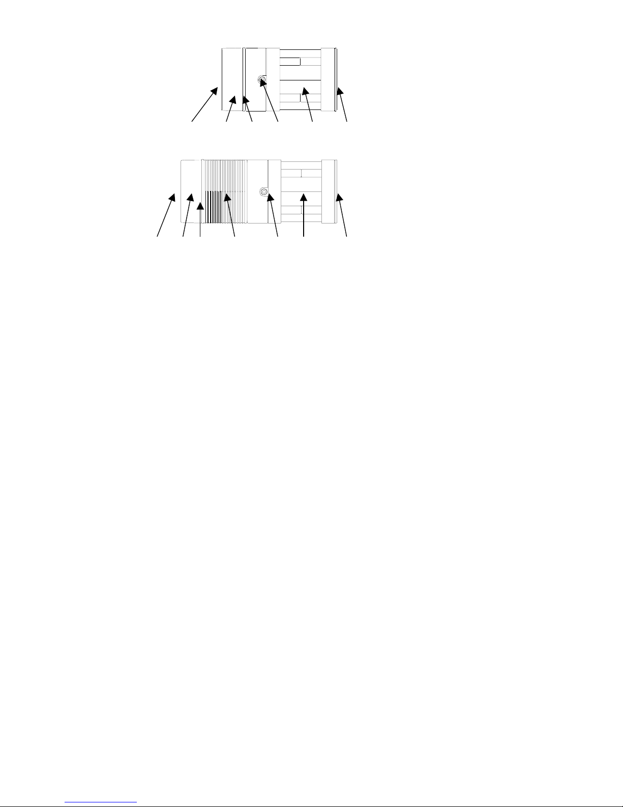
DESCRIPTION OF THE SWITCH UNIT
Programme A: By pressing the plus (+) switch, the lamp is turned on to 125% power.
The minus (–) switch turns the lamp off.
Programme B: Each time the + switch is pressed for approx. ½ second, the lamp
power will increase 25%. The – switch operates in the same way to
reduce the power 25%. When the lamp has reached the max. or
minimum power setting and the switch is pressed again, the lamp will
blink once to show that the end of the scale has been reached.
If the + switch is pressed for approx. 1 second, the lamp is turned on to
it’s max. (125%) power setting. The – switch pressed for approx. 1
second will turn the lamp off.
Programme C: If the + switch is pressed continuously, the lamp will increase the power
(in 5% steps) until the maximum power is reached (125%) when the
lamp will blink once. Pressing the – switch continuously will reduce the
power in 5% steps to the minimum power setting of 25% when the lamp
will blink once.
If the – switch is pressed for only approx. ½ second, the lamp will turn
off. Pressing the + switch for only approx. ½ second will turn the lamp
on to it’s last power setting.
Programme T: In programme T, the lamp stays on as long as the + switch is pressed
for sending Morse signals. The power is 125%.
Programme D2 Gas discharge module
The micro processors immediately recognise that the gas discharge
module is in place. No manual adjustment is necessary.
Pressing the + switch will activate the electronics to 100% power.
Thanks to a special technology, the gas discharge xenon bulb, which
normally cannot be dimmed, can be operated at 75% power.
If the – switch is pressed for only approx. ½ second, the lamp will
switch over to 75% power setting.
Pressing the – switch again for only approx. ½ second will turn the light
off. If the – switch is pressed long for approx. 1 second, the light will
turn off from the 100% power setting.
A feature of the gas discharge technology is the long warm up
phase. In the first 45 seconds of operations the gas discharge bulb
needs approx. 80% more power than when it is reached it´s
working temperature. For this reason, it is recommended to use
the gas discharge technology for continued operation.

Hartenberger Underwater Lamp mega compact / mega compact D2 Instructions for use
9
Constantly turning the lamp on and off will also reduce the life
expectancy of the bulb.
DIGITAL DISPLAY
The percentage power setting of the halogen bulb is shown in the top
line of the display. The resulting remaining burn time at this setting is
shown in minutes in the lower line of the display. The remaining burn
time can vary up to 1 or 2 minutes due to technological reasons.
Despite the prognosed remaining burn time being calculated with
a high degree of technological data, the time shown may vary
within a few minutes.
When using the gas discharge module, the warm up phase produces
high variances in the remaining burn time due to the high power drain.
The remaining burn time is extended as the power drain reduces. For
this reason, the remaining burn time display blinks during the
warm up phase when using the gas discharge module.
When the lamp is turned off, there is only a display in the bottom line
which shows the charge state of the cells in %. The background display
lighting is deactivated 15 minutes after the lmap is turned off. The
display can be activated by pressing either the + or the – switch.
LOW LEVEL CAPACITY WARNING
When the lamp blinks 3 times, the user is warned of the immanent end
of the burn time of the lamp. When the lamp is being used with the
standard 50 watt halogen bulb at 125% power, this will be
approximately 3 minutes after the 3 blinks. If applicable, you should
abort the dive as fast as possible and turn the lamp off (reduce the
power setting). Further use of the lamp will cause increase the wear
and tear on the cells.
DISCHARGE PROTECTION
At the latest, the lamp should be turned off and no longer operated
when it starts to blink continuously.
Warning ! Further use of the lamp will damage the cells and should only be
practised in an emergency.
The duration of blinking with the standard halogen bulb set at 100%
power is approx. 1-2 minutes. If the lamp is switched over to 25%
power, then approx. 3 minutes of continuous light is available. After
this, the light will go into a blinking mode once again.
DISCHARGE PROTECTION
The discharge protection will turn shut down the lamp after the
continuous blinking. In the case of an emergency where light is
necessary, the lamp (if possible after a short pause) can be reactivated
and will automatically turn on at 25% power setting. The cells are
almost certainly damaged should this mode of operation be
selected.
EMERGENCY MODE
Under certain unforeseeable circumstances such as extended
periods of storage, high levels of self discharge or ageing of the
cells, there can be a discrepancy between the remaining burn time
in the display and the actual remaining burn time.
In this case, the electronics will immediately recognise the

Hartenberger Underwater Lamp mega compact / mega compact D2 Instructions for use
10
imminent end of the burn time and that the display is showing an
incorrect value.
When the lamp is being used with a standard halogen bulb, the
user will be warned by the lamp blinking 6 times and subsequently
automatically switching over to 25% power. The remaining burn time
is approx. 2 minutes. The display blinks continuously until the lamp is
turned off.
In gas discharge operation, the lamp blinks 6 times and the power
is reduced to 75%
The remaining burn time is approx. 1 minute, after which the lamp will
turn off automatically.
After the lamp has operated in emergency mode, a reference cycle
is recommended (see page 11). During this cycle the lamp can
calculate the actual cell capacity and calibrate the remaining burn
times.
RECALL MODE
The micro processors in the switch electronic and the power pack
correspond and exchange data with each other to allow a variety of
functions and data storage.
Some of this data can be recalled via the switches and shown in the
display.
The recall is then made by depressing the – switch and keeping it
pressed.
After approx. 4 seconds, the display will appear with all numbers as O
(ready for commands)
While the lft – switch is kept depressed, short actuation of the right +
switch will call up the following data each one after the other:
Data No 1st Line/2nd Line
1 6 digit serial number 1XX / XXX / Num
2 Date of manufacture 2 / MM.J
3 Manual set up of cell status to 100% 3 / 100 / %
4 Reference cycle for cell capacity 4 / rEF /
5 Actual temperature 5 / XX / °C
6 Max. Temperature value 6 / XX / °C
7 No of charge cycles (every connection) 7 / XXX / Num
8 No of full charges above 90% 8 / XXX / Num
9 No of discharges to continuous blinking (0%) 9 / XXX / Num
10 No if discharges up to shut down 10 / XXX / Num
11 No of reactivations after shut down 11 / XXX / Num
12 Total duration of use 12 / XXX / Std.
13 Maximum charging current 13 / XX.X / A
The manufacturer also has the facility via a PC interface to download
additional data such as history of the cells (voltage records, charging
times, discharging times and periods of storage).
EXTENSION OF THE WARRANTY
The current EEC regulations call for a 6 Month warranty of
rechargeable cells. If the cells in your lamp are handled with care the
average life expectancy is 4-6 years or 300 – 500 charge/discharge
cycles. Incorrect handling of the cells will shorten this life expectancy
drastically. The data stored in the electronics serves as a reference and
can be analysed in the interest of the consumer to extend the warranty.
Should the power pack fail within 2 years after purchase, and the

Hartenberger Underwater Lamp mega compact / mega compact D2 Instructions for use
11
data in the memory shows correct handling of the cells, a warranty
repair or a fair offer will be made.
DISPLAY CORRECTION
• If the display does not show 100% charge status after a correct
charging cycle (charger has turned itself off and the cells are
warm), then a re-calibration of the state of charge display is
recommended to establish a 100% state of charge in the display.
In the previous section of data recall, the 3rd recall function is the 100%
manual reset in the display. When the left – switch is released during
this function in the display, the charge status will automatically be set to
100%.
REFERENCE CYCLE
After numerous charge/discharge cycles or extended periods of
storage, it is possible that the remaining burn time in the display does
not correspond to the actual remaining burn time.
At the latest when the lamp goes into emergency mode ( as previously
described), a reference cycle should be carried out.
The lamp must be fully charged and fitted with a 50 Watt halogen bulb.
Remove the unit from the housing. The recall mode is then selected by
pressing the left – switch and then pressing the right + switch until
„rEF“ appears in the display (recall function no 4). Release the left –
switch. In this moment, the lamp will turn on to 125%. Stand the lamp
on it rear end until it turns itself off (after approx. 50 minutes).
Do not touch any other switches.
Warning ! During this cycle when the lamp is standing on it’s end, a great
deal of heat will be dissipated from the bulb. Caution is to be
exercised.
After the lamp has turned itself off, the correction factor will appear in
the display which is then used for future remaining burning time
calculation so that future values in the display will be as accurate as
possible.
SOS-EMERGENCY SIGNAL (NOT POSSIBLE WHEN USING THE D” GAS DISCHARGE BULB)
The electronic provides the facility to send an emergency signal SOS
according to the Morse alphabet (3 x short, 3 x long, 3 x short). This is
activated by pressing the + switch so long that the maximum power is
selected, then keeping the + switch pressed for a further 4 seconds.
After the SOS feature is selected, lamps in the B or C mode can adjust
the power of the signal using the +/- switches. The remaining duration
of the emergency signal is shown in the display and is approx. 2-3
times longer than the continuous use remaining burn time of the
halogen lamp being used. When the power pack is almost completely
discharged, the brightness will be reduced.
To deactivate the SOS signal, press the – switch for approx.3 seconds.
To initiate a break in the SOS signal, both switches +/- are pressed
together. A short press of the + switch will reactivate the SOS mode to
the previous setting.
This feature should only be used in an emergency. Should you
require the SOS distress signal in an emergency, we recommend
that the signal is turned off when the intensity of the flashing
reduces, and to turn the SOS signal back on should help be

Hartenberger Underwater Lamp mega compact / mega compact D2 Instructions for use
12
sighted.
OVER-VOLTAGE / DIMMER
The HLX bulbs which we use have a much greater efficiency than
standard halogen bulbs. Using a 12 cell power pack, we have a power
supply of 14.4 volts. This allows the 12v bulb to be operated
continuasly with an over-voltage of approx. 12.8 volts. The electronics
switch the bulb on slowly thus preventing the coil in the bulb from
burning out. The resulting increase in brightness is approx. 30% more
than the stated power. The micro controller can accurately monitor the
energy disserpation to the bulb and ensures a continuous colour
temperature over the entire discharge process and operation.
The life expectancy of the bulb of approx. 100 hours, is reduced
because of the over-voltage to approx. 70 hours.
Using the lamp at reduced power settings saves energy and extends
the burning time in a single charge cycle. Permanently operating the
lamp at reduced power settings will however produce a grey coating on
the bulb’s glass. If reduced brightness is required on an extended
basis, then a lower power halogen bulb is recommended.
GAS DISCHARGE MODULE D2
In addition to the standard halogen bulb, the mega compact can also
be used with a gas discharge xenon bulb. After removing the reflector
and the halogen bulb, the gas discharge module (including electronic
control and xenon bulb) can be plugged into the front of the power pack
The 3 contact pins prevent cross poling. The reflector is then fitted to
the gas discharge module.
For use with the gas discharge module, a 5.5cm (2”) housing extension
is required.
The brightness of the 35 watt gas discharge xenon bulb is approx.
equivalent to a 100 watt halogen bulb. The power drain of the gas
discharge xenon bulb including the ignition and transformer is less than
that of a 50 watt halogen bulb.
The 4500° Kelvin colour temperature of the gas discharge xenon bulb is
however much bluer than the warm 3600° Kelvin temperature of the
halogen bulb. The ideal applications for gas discharge technology
include industrial applications, cave diving, etc.. A “holiday diver” will
almost certainly miss the red spectrum of the gas discharge light.
The gas discharge bulb allows operation with 100% and 75% of the
available power. Further dimming is not technically possible.
After turning the xenon bulb on, it takes about 45 seconds to reach it’s
full brightness. During this so called ignition and warm up phase, the
power drain is much higher than when the bulb has reached it’s working
temperature.
Although the electronics allow the lamp to be switched off and then
immediately afterwards switched back on, it is recommended to leave
the lamp on for the entire duration of the dive.
The life expectancy is approx. 2000 hours although this will be
drastically reduced when the lamp is frequently switched on and off.
The SOS emergency signal mode is not possible with the xenon gas
discharge module.
AFTER EACH USE
• After use, the lamp must be thoroughly rinsed in clean fresh water.

Hartenberger Underwater Lamp mega compact / mega compact D2 Instructions for use
13
During the rinsing, the switches must be frequently operated to
ensure contamination (salt water and/or sediment) is rinsed out of
the mechanism.
• Check the lamp immediately after the dive for evidence of a
possible flooding of the housing. Should the housing have flooded
then refer to the problem diagnosis on page.
• The cells should be charged as soon as possible after use.
TRANSPORT
TRANSPORT LOCK
During transport, the + switch must be secured against inadvertent
operation. For this purpose, the transport lock is moved to the right into
the “lock” position. The + switch should now not be able to be pressed.
(Please check !).
Warning ! During extended unattended periods of transportation, we
recommend removing the halogen bulb from the socket.
The gas discharge module can be re-plugged onto the cell pack
after approx. 160° rotation, thus preventing it from being activated.
Caution: In this configuration, one of the plugs is located in one of the
halogen bulb stowage housings, danger of breaking glass.
REMOVAL/REFITTING THE BULB
To replace, remove or refit the halogen bulb, first remove the rear
housing cover. Remove the internal unit from the housing. Remove the
reflector unit and the halogen bulb is easily accessed in it’s socket.
When the heat protection shield is rotated, the spare bulb stowage can
be accessed.
Warning ! After using the lamp, the heat protection shield remains hot for
some time after the lamp has been turned off.
The lamp should never be operated without the heat protector
shield in the correct position.
Do not touch the halogen bulb with your bare fingers. Residue on your
fingers can remain on the glass during normal use may form carbon.
This will reduce the efficiency of the bulb. Use a clean cloth or tissue to
remove the bulb from the socket. When refitting or replacing the bulb,
ensure that it is located all the way into the socket. To produce an even
illumination, it is imperative to ensure that the bulb sits upright in the
socket. Assemble the lamp and check for correct operation.
The xenon gas discharge bulb should only be replaced by the
manufacturer. Self assembly is possible but voids the warranty.
STORAGE
The lamp should be stored in a fully charged condition with the housing
closed securely. An ideal storage temperature is between 15 and 25°C,
(60 and 75°f). Under no circumstances should the lamp be subjected to
temperatures above 45°C (110°f).
The rechargeable cells will slowly discharge when not in use,
(depending on the ambient temperature up to 60% discharge in one
month!). We recommend therefore that the cells be charged
approximately once a month when the lamp is not in use.
For extended periods of storage, the power pack should be removed
from the housing and stored separately in a suitable cool dry place,
(see preparation for charging page 14).

Hartenberger Underwater Lamp mega compact / mega compact D2 Instructions for use
14
Regularly check the cells for signs of corrosion or gas leakage, (the
protective skin showing signs of bubbling, floury or white residue
between the cells or in the housing, corrosion around the charging
socket.) Should you discover signs of leakage or corrosion, return the
lamp immediately to the manufacturer.
CHARGING
INTRODUCTION IN THE CHARGING OF NICKEL METAL HYDRIDE CELLS
Nickel Metal Hydride (NMH) cells are generally described as being gas
tight cells. The position of the cells during the charging process is
therefore irrelevant as no electrolyte can escape.
There is however no supplier of cells that will guarantee this
feature for the entire life of the cells!
During the charging or discharging process, the NMH cells may
produce and over pressure inside, opening the integrated over pressure
relief valve.
Should this occur, the electrolyte, or Hydrogen can escape from the
cells. Because the electrolyte is a very aggressive acid, and additionally
conducts electricity, this may lead to the galvanic corrosion of the cells,
and a destruction as a result of the contact with the acid.
The escaping hydrogen can combine with oxygen in the air and form a
highly explosive gas. A single cell the size of a standard D cell battery
can produce up to 25 litres, (1 cu ft) of gas!
It is for this reason that nickel metal hydride cells should always
be removed form a housing before they are recharged. Only then is
the safe use and longest possible life of the cells guaranteed.
MEMORY EFFECT
The so called Memory Effect is the common term for the reduction in
the capacity of the cells as a result of charging the cells in a partially
discharged condition. (e.g. A wireless telephone hand set has a battery
life of 24 hours, but is replaced on the station and therefore charged
after 3 hours). The common technique for overcoming this is to fully
discharge the cells before charging.
We regard this as being more harmful for underwater lamps with 10
cells. The constant discharge down to the cut-off voltage limit can
overload individual cells and disrupt the balance within the matched cell
pack. This may result in an individual cell “dropping out“.
We recommend that for every 10 to 20 cycles where the cells are
partially discharged, that the lamp is fully discharged until the Low
Level Capacity Warning (when the lamp blinks 3 times). The more
often the cells are taken to their maximum capacity, the higher the
strain on the individual cells.
NMH cells are considerably less sensitive to this memory effect than
Nickel Cadmium cells.
PREPARATION FOR CHARGING
For the charging procedure you will need a clean, dry working area with
a mains socket nearby. Charge the cells in an environment which is as
dry and clean as possible, with a resistant work surface. (Sealed cells
can also leak under poor conditions). The ambient temperature
should not exceed 45°C (110°F). The power pack must be removed
for charging. (See Page 6). If the area to be used for charging is

Hartenberger Underwater Lamp mega compact / mega compact D2 Instructions for use
15
contaminated with dust or dirt, then we recommend that the cell pack
should be removed from the rear screw fitting, and that the housing is
subsequently closed protecting the O-Rings and the sealing surfaces
which would otherwise be exposed to possibly contamination. Stand the
power pack in an upright position with the reflector down. This will avoid
the collection of dirt and/or dust on the reflector and halogen bulb. The
charging socket is located on the side of the reflector unit.
Warning ! When using the gas discharge technology, first remove the gas
discharge module from the power pack before removing the cell
pack from the electronics. The assembly is the reverse procedure.
THE USE OF GENERIC CHARGERS
Warning ! Chargers other than those supplied by Hartenberger for use with
this lamp must be checked by a qualified electrician for
compatibility before attempting to use them. The guarantee will be
lost due to improper use. Improper use may lead to the leakage of
electrolyte and/or hydrogen gas. The guarantee will be lost due to
improper use.
Off Shore I/12 Charger
This charger utilises the latest in electronic charger technology with a
wide range input voltage (100v - 250v) with frequencies of between 45 -
65 Hz. (There is no need to manually select the input voltage).
All Hartenberger power packs with 10 and 12 cells (Nickel Cadmium or
Nickel Metal Hydride) will be automatically recognised by the charger,
and charged as fast as possible. The charging current can reach 1.0
amps.
The charger cable should first be plugged into the charging socket.
The charger is activated by plugging it into the mains supply. (There are
adapters for the most common types of mains plugs which can be
easily slotted onto the charger).
All the functions of the charger are monitored via a LED.
Signal from the LED
Red Input voltage is present, the charger is functioning properly.
Blinks Red The cells are fully charged and maintained with a trickle charge.
Blinks Red fast The cells are fully discharged (starting regeneration).
Out No mains voltage present.
Do not use overdue force when fitting the plug into the socket. Avoid
any chance of short circuiting the contacts of the plug or the power
pack.
The charger has an integrated mechanism protecting it against
overheating and large fluctuations in mains voltage. Should the
protection cut in, the charging process will be interrupted. After the
mains plug has been removed from the mains socket for a few minutes,
the charger will then be ready for use again. Care must be taken to
achieve adequate cooling in extreme environments.

Hartenberger Underwater Lamp mega compact / mega compact D2 Instructions for use
16
Do not operate the lamp immediately after the charging cycle is
completed. Do not point the lamp at yourself or in the direction of
other persons.
Maximum cells Charging times using an Off-Shore I/12 Charger for fully discharged
Lamp Type Voltage/Capacity Charger Charging time
mega compact 14.4v / 4.5Ah Off-Shore I/12 approx. 5 hrs
Off Shore II Charger
This charger utilises the latest in electronic charger technology with a
wide range input voltage (110v - 250v) with frequencies of between 45 -
65 Hz. (There is no need to manually select the input voltage).
All Hartenberger power packs with between 5 and 12 cells will be
automatically recognised by the charger, and charged as fast as
possible. The charging current can reach 2.0 amps.
The function of the charger is monitored via 2 light emitting diodes
(LED’s) with varying colours and flashes. The charger is activated by
plugging it into the mains supply.
LED I
Green Input voltage is present, the charger is functioning properly.
Red Input voltage is present, the charger is overloaded or defective.
Out No input voltage present.
The charger cable should now be plugged into the charging socket in
the power pack. Do not use overdue force when fitting the plug into
the socket. Avoid any chance of short circuiting the contacts of
the plug or the power pack.
Red No Cells are connected (interruption).
Green blinking Rapid charge up to approx. 95% of capacity.
Green Trickle charge with a reduced current.
Out Maintenance charge, Cells are fully charged.
All the functions of the charger are monitored by a controller in the
charger. This monitoring has a time lag when the function of the
charger changes, and may lead to a slight delay in the LED’s reacting,
(1-5 seconds).
The charger has an integrated mechanism protecting it against
overheating and large fluctuations in mains voltage (LED I turns red).
Should the protection cut in, the charging process will be interrupted.
After the mains plug has been removed from the mains socket for a few
minutes, the charger will then be ready for use again. Care must be
taken to achieve adequate cooling in extreme environments.
• Do not operate the lamp immediately after the charging cycle is
completed. Do not point the lamp at yourself or in the direction of
other persons.
Maximum cells Charging times using an Off-Shore II Charger for fully discharged
Lamp Type Voltage/Capacity Charger Charging time
mega compact 14.4v / 4.5Ah Off-Shore II approx. 2.5 hrs

Hartenberger Underwater Lamp mega compact / mega compact D2 Instructions for use
17
CARE AND MAINTENANCE
HOUSING
We recommend that from time to time the housing surface is
impregnated with silicone. The chance of calcium depositing on the
surface of the lamp is reduced and the scratch resistance properties of
the housing surface are also improved.
SERVICE
Action to be taken Interval By Owner Workshop
Impregnate Housing surface After repeated use X
Visual inspection of the rear
screw fitting O-Rings, clean
and lubricate as necessary
After the housing is opened X
Cleaning the switch After every dive cleaning with
clear fresh water and pressing
the button pad plus and minus
approx. ten times
X
Replace rear screw fitting O-
Ring
annually or after 200 dives,
which ever comes first
X
Replace Front Glass O-Ring 4-5 years X
Replace Transport Safety Pin
O-Ring
Annually or if the pin is
defective
X
Replace Halogen Bulb Life expectancy approx. 100
hours
X
Replace NMH Cell Pack Life expectancy up to approx.
300 to 500 charging cycles
X
RECORD OF DATES WHEN MAINTENANCE WORK WAS CARRIED OUT
Rear screw fitting
O-Rings replaced
Front Glass O-Ring
replaced
LCD-Display O-
Ring replaced
Halogen Bulb
replaced
Notes/Comments:

Hartenberger Underwater Lamp mega compact / mega compact D2 Instructions for use
18
FAULT DIAGNOSIS
Problem Cause Action to be taken
Water enters the
housing:
Defective or contaminated
O-Ring.
Abort the dive as soon as is safely
possibly. Open the lamp.
1. A few drops
are present.
1. Dry the lamp and power pack with a
clean cloth.
2. Housing is
flooded with fresh
water.
2. Dry the power pack and return it to
the manufacturer
3. Housing is
flooded with
Saltwater.
3. Rinse the lamp and power pack with
ample fresh water and return the lamp to
the manufacturer..
Switches sticking Sand or salt residue in the
mechanism
Clean the switches (see below)
Lamp does not
illuminate.
1. Electronic circuits have
automatically switched the
lamp off.
2. Cells discharged.
3. Defektive bulb.
1. Conduct Reset procedure in
accordance with the instructions on
page.
2. Charge cells.
3. Replace bulb in accordance with the
instructions on page
LED does not
illuminate.
1. No Mains.
2. Charging cable not
plugged in.
3. Bad contact on charging
plug.
1 Check mains supply.
2. Plug in charging cable.
3. Check charging plug security.
Off-shore II
LED I illuminates
red
Charger protection switch
active.
Unplug the mains cable and allow 3
minutes to cool down. Reconnect the
mains cable.
CLEANING THE SWITCHES
If the switches start to stick, they must be cleaned by rinsing the lamp
under fresh clean water for an extended period. Operate the switches
under running water to restore the correct function.
If this is not successful, the switches must be removed by removing the
entire rear cover. This work can be carried out by a technially trained
lay person.
Unscrew the 4 cross head screws (page 3 fig. 2) and carefully remove
the rear cover. The 2 switches and the transport lock can now be
removed together with their springs which are located underneath.
Sand granulkes and salt crystals can be removed by rinsing the
switches.
Assemble in the reverse order.
Grease the screws with silicone grease and refit them tightening them
good hand tight.

Hartenberger Underwater Lamp mega compact / mega compact D2 Instructions for use
19
SPARE PARTS
O-Ring Dimensions Elasticity Material
Glass 68x3.0 50°shore Viton, Blue
Window LCD 58x3.5 50°shore Viton, Blue
Screw Fitting 68x3.0 50°shore Viton, Blue
Screw Fitting 68x2.0 50°shore Viton, Blue
Reflektor unit 68x3.0 50°shore Viton, Blue
Reflektor unit 68x2.0 50°shore Viton, Blue
Heat protection shield 20x2.0 50°shore Viton, Red
Halogen Bulb G6.35 12V/30W 12V/50W 12V/100W
D2 Xenon Gas Discharge Bulb 35W
ACCESSORIES
NEOPRENE SLEEVES
Neoprene sleeves for the housing offer protection and a reduction in
weight in the water and are available in the colours yellow and black.
CARABINER CLIPS
For securing the lamp to a suitable point on the diving equipment.
SPARE CELL PACKS
For rapid turn-around between dives, a spare 14.4v / 4,5Ah cell pack.
FLOOD REFLECTOR
For film or video use for an even illumination over the entire beam.
REFLECTOR MODULE SPOT(STANDARD)
Reflector unit with a narrow beam for penetrating illumination
ELECTRONIC MODULE MEGA D2 WITH MEGA D2 HOUSING
To modify a standard mega (Halogen bulb) to gas discharge D2
technology.
HOUSING MEGA (HALOGEN)
To modify the Mega D2 (gas discharge) to halogen technology.
Rights reserved for technical changes All forms of Reproduction forbidden
Issue 09.2002
Hartenberger
Unterwassertechnische Geräte GmbH
Rennebergstr. 19 D-50939 Köln Germany
Telefon: +(49) 221 415000
Fax: +(49) 221 415050
www.hartenberger.de
Other manuals for mega compact
1
This manual suits for next models
1
Table of contents
Other Hartenberger Flashlight manuals