HARTING HAIIC MICA User manual

HARTING HAIIC MICA Hardware Development Guide

HAIIC MICA Hardware Development Guide
2 HARTING IT Software Development
3. Edition 2016, 11/16
Doc No 20 95 100 0003 / 99.01
© HARTING IT Software Development, Espelkamp
All rights reserved, including those of the translation.
No part of this manual may be reproduced in any form (print, photocopy, microfilm or any
other process), processed, duplicated or distributed by means of electronic systems without
the written permission of HARTING Electric GmbH & Co. KG, Espelkamp.
Subject to alterations without notice.
This hardware development guide explains how the MICA can be connected to a power supply,
the assignment of the GPIO channels as well as how to customize your own circuit board and
front bezel.

HAIIC MICA Hardware Development Guide
HAIIC MICA Hardware Development Guide, Edition 2016 3
Contents
Contents ........................................................................................................................3
1Power Supply.........................................................................................................4
1.1 PoE..............................................................................................................4
1.2 24V Supply.................................................................................................4
1.3 LED Status Display ...................................................................................4
2GPIO........................................................................................................................5
3MICA Customizable Circuit Board .......................................................................9
3.1 Technical Description...............................................................................9
3.2 Thermal Behavior......................................................................................9
3.3 Front Bezel...............................................................................................11
4Attachments.........................................................................................................12
HAIIC MICA Hardware Development Guide
4 HARTING IT Software Development
1 Power Supply
1.1 PoE
The MICA can be supplied with electricity with Power over Ethernet. When using Power
over Ethernet, connect the device to a PoE-capable switch with a suitable M12 X-coded ca-
ble.
1.2 24V Supply
Alternatively the MICA can be supplied with electricity over a Harting breakout cable (24
VDC) with a M12 plug-in connector where the input cable is grey/pink and the ground wire is
red/blue. When using the M12 plug-in connector observe the assignment of the pins. Then
connect the M12 connector to a power supply.
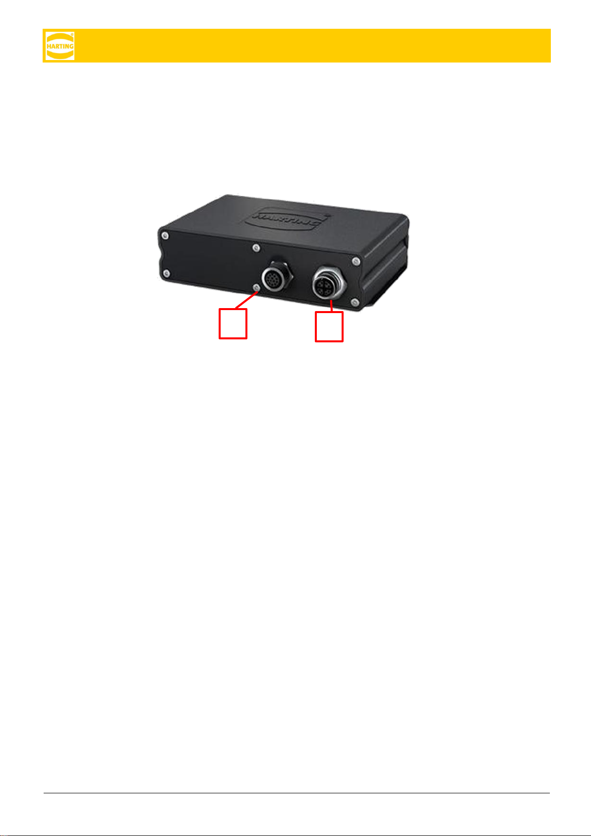
1.3 LED Status Display
The LED to the left of the M12 A-coded plug shows the status of the boot process. Red sig-
nifies the MICA is booting. Red blinking signifies a system error. Green signifies the system
is completely booted. Green blinking signifies an erroneous state.
The LED to the left of the X-coded plug signifies activity of the network chip and blinks ac-
cordingly.
A
B
A
Figure 1: A-coded M12 GPIO 12 pin outlet (A) and M12 X-coded Ethernet / Power over Ethernet
8 pin outlet (B)

HAIIC MICA Hardware Development Guide
HAIIC MICA Hardware Development Guide, Edition 2016 5
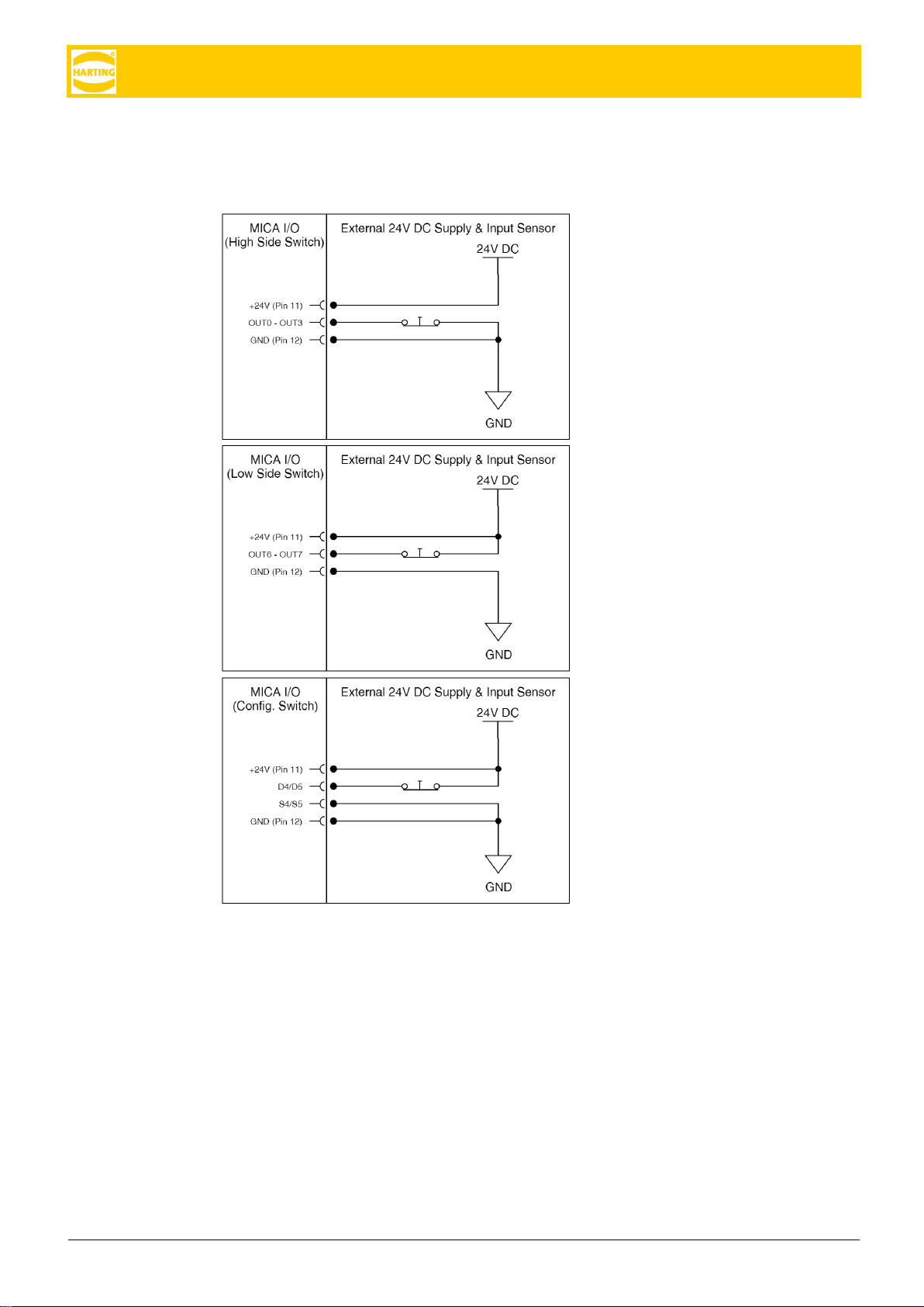
2 GPIO
The GPIO channels are assigned in the following way. If MICA is powered over 24V with the
breakout cable, the GPIO voltage matches the input voltage. The color coding is explained
in figure 3.
Caution: GPIO channels can be reconfigured from Input to Output in software. Check that all
channels are in default configuration when attaching them to a new hardware device.
Figure 2: Assignment of the GPIO Channels in Harting Breakout Cable
HAIIC MICA Hardware Development Guide
6 HARTING IT Software Development
You can load a single channel with max. 50mA, a combination of channels with 250mA to
avoid an overheating of the TLE chip behind the channels. You can use the GPIO channels
as inputs for e.g. signals:
Pins HS1 (OUT0) –HS4 (OUT3) for a
high side switch
Pins LS1 (OUT6) –LS2 (OUT7) for a
low side switch
Pins SWD1(D4) / SWD2(D5) and
SWS1 (S4) / SWS2 (S5) for a
configurable switch
HAIIC MICA Hardware Development Guide
HAIIC MICA Hardware Development Guide, Edition 2016 7
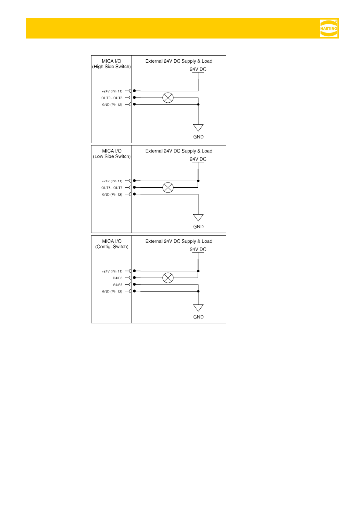
You can use the GPIO channels as
outputs:
Pins HS1 (OUT0) –HS4 (OUT3) for a
high side switch
Pins LS1 (OUT6) –LS2 (OUT7) for a
low side switch
Pins SWD1 (D4) / SWD2 (D5) and
SWS1 (S4) / SWS2 (S5) for a
configurable switch
HAIIC MICA Hardware Development Guide
8 HARTING IT Software Development
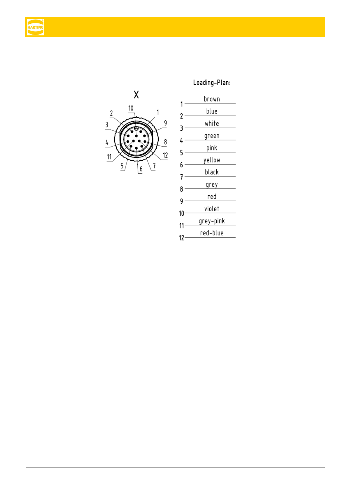
Figure 3: Color Coding of Channels in Harting Breakout Cable (see attachment 1)
HAIIC MICA Hardware Development Guide
HAIIC MICA Hardware Development Guide, Edition 2016 9
3 MICA Customizable Circuit Board
3.1 Technical Description
In the technical drawing fig. 1 the dimensions and measurements of the printed circuit board
[PCB] of the MICA functional module are depicted. On the left you see the top view, in the
middle the side view and on the right the bottom view. The eight metallized areas in the mid-
dle of the top view depict module connector pins. The GND is the signal ground. The VDD
(supply voltage) supplies the device with 5V +/- 10% and 1A. The pins VBUS, D-, D+, GND,
GND define the USB 2.0 connection. A functional module should perform like a self-pow-
ered USB 2.0 compatible device.
All metalized mounting holes and mounting pads should be connected to GND.
3.2 Thermal Behavior
At the bottom of the functional module a thermal interface material (for example Bergquist
GF 1500) should be applied.
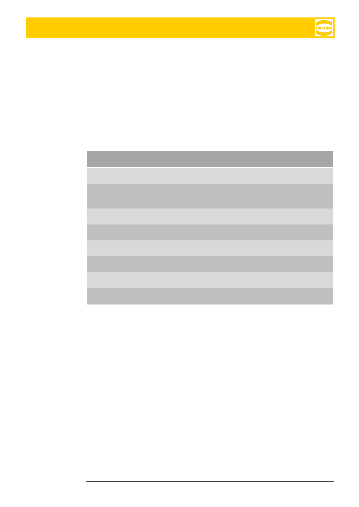
Connector Pins
Function
GND
signal ground
VDD
Supply voltage, supplies the device with 5V +/- 10%
and 1A
VBUS
defines the USB 2.0 connection
D-
defines the USB 2.0 connection
D+
defines the USB 2.0 connection
GND
defines the USB 2.0 connection
GPIO
GPIO Reserved for future use
GND
GPIO Ground

HAIIC MICA Hardware Development Guide
10 HARTING IT Software Development
Figure 4: Printed Circuit Board (PCB)
Figure 5 Allocation of Connector Pins (top to bottom)
HAIIC MICA Hardware Development Guide
HAIIC MICA Hardware Development Guide, Edition 2016 11
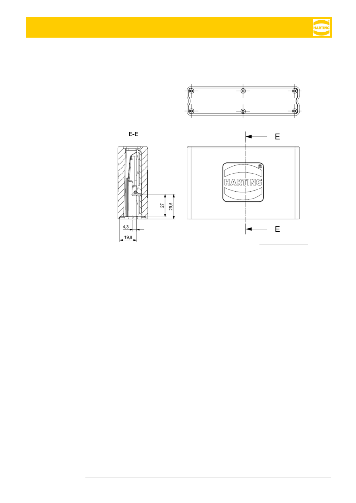
3.3 Front Bezel
The front bezel can be customized with the proper connectors to fit your application. The po-
sition of the customizable circuit board in relationship to the front bezel is shown in figure 6.
Figure 6 Position of the Cusomizable Circuit Board in Relationship to Front Bezel
HAIIC MICA Hardware Development Guide
12 HARTING IT Software Development
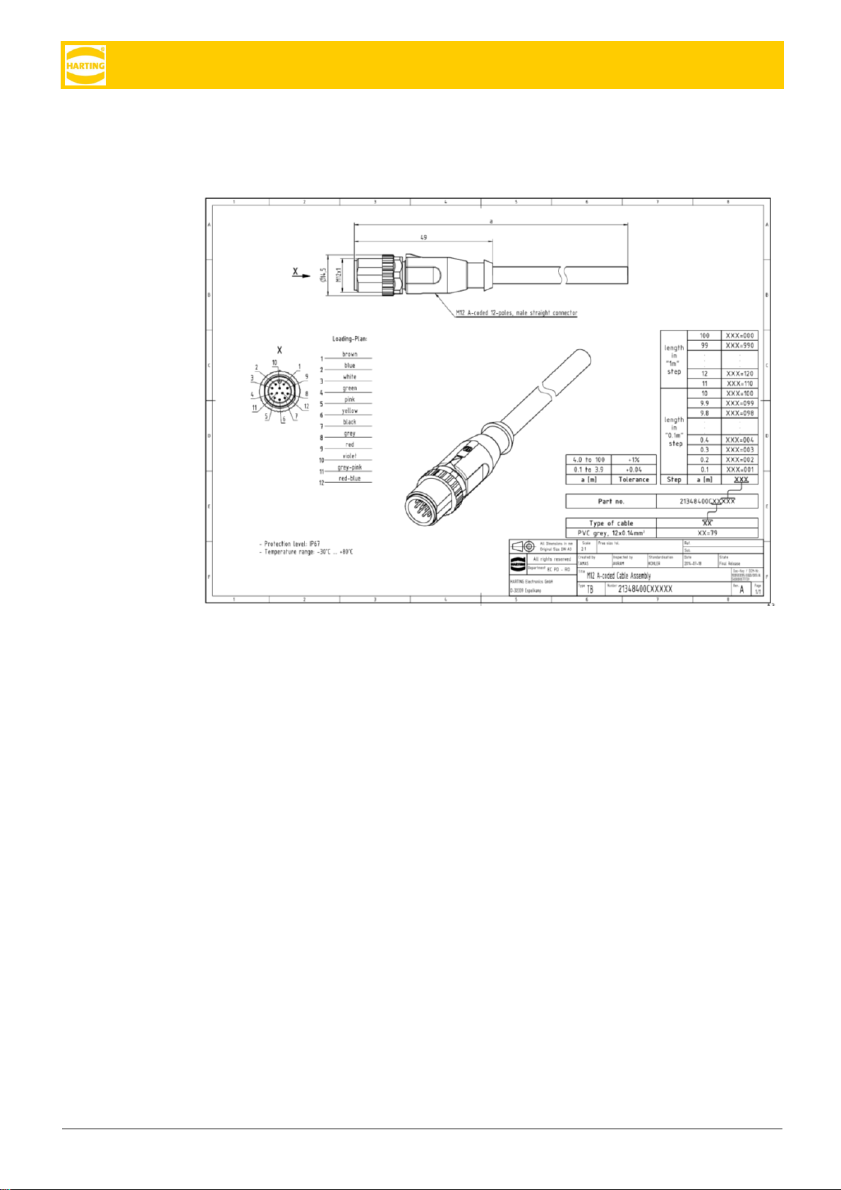
4 Attachments
Figure 7: M12 A-coded Cable Assembly of Harting Breakout Cable

HAIIC MICA Hardware Development Guide
HAIIC MICA Hardware Development Guide, Edition 2016 13
Document Version
1.3.0
Chapter LED Display has been added.
Table of contents
Popular Network Hardware manuals by other brands


Security Camera King
Security Camera King NVR-EL-32 manual

TASSTA
TASSTA T.Bridge 4WIRE Deployment guide

Ruijie
Ruijie Reyee RG-EST Series Faqs

Texecom
Texecom Premier IXP-W installation manual

GAI-Tronics
GAI-Tronics Elemec3 013-02-0095-002 Console manual

Ubiquiti
Ubiquiti PowerBeam M5 PBE-M5-400 quick start guide


