HARTING 09 35 000 9915 User manual

Bestell-Nummern
09 35 000 9915 SCRJ POF Werkzeug-Set
09 35 000 9914 Ersatz-Schneideeinrichtung
Allgemeines
Die Werkzeuge dürfen nur in technisch einwandfreiem Zu-
stand sowie sicherheits- und gefahrenbewusst benutzt
werden und sind nur für den in der Bedienungsanleitung be-
schriebenen Zweck zu verwenden.
Verwendungszweck
Das Werkzeugset wird zum Schneiden, Abisolieren und Kon-
fektionieren von Lichtwellenleitern (POF-Kabel) mit einem
Kabeldurchmesser von 2,2 mm und einem Faserkerndurch-
messer von 1,0 mm für Steckverbinder vom Typ SCRJ einge-
setzt.
Transportsicherung
Vor dem ersten Benutzen der Schneideein-
richtung des Crimp- und Schneidewerkzeugs
(Abb. 4) ist die Transportsicherung (Gewinde-
stift) mit dem beigelegten Innensechskant-
schlüssel zu lösen bzw. zu entfernen (siehe
Etikett).
!
Schneideeinrichtung
Die Schneideeinrichtung ist als Ersatzteil problemlos aus-
tauschbar (Bestellnummer 09 35 000 9914). Sie besteht aus
einem Vorschubgetriebe mit Restschnittanzeige, Rundmes-
ser und Schwenkhebel.
Mit jedem Schnitt wird das Messer um 12° im Uhrzeigersinn
weitergedreht und somit eine gleichmäßige Ausnutzung des
Messerumfangs realisiert.
Nach einer vom Werk festgelegten Anzahl von Schnitten
(2500) blockiert die Schneideeinrichtung automatisch und
muss ausgetauscht werden. Über eine Restschnittanzeige
werden die letzten 150 Schnitte vor dem Blockieren der
Schneideeinrichtung angezeigt.
Austausch der Schneideeinrichtung
Der An- und Abbau der Schneideeinrichtung wird über die
Befestigungsschraube (Abb. 12) realisiert. Durch Lösen der
Schraube kann die Schneideeinrichtung seitlich vom Zan-
gengrundkörper abgezogen werden.
Beim Anbau der Schneideeinrichtung ist zu beachten, dass
vor dem Anziehen der Befestigungsschraube das gerade
Ende der Rückholfeder hinter die Klemmbacken der Zange
gebracht wird und die Schneideinrichtung an dem Anschlag-
stift anliegt.
Anschließend ist die Transportsicherung (Gewindestift) mit-
tels Innensechskantschlüssel zu lösen.
Abb. 1
Rund-
messer
Transport-
sicherung
Rest-
schnitt-
anzeige
Schwenk-
hebel
Wartung und Instandhaltung
Das Abisolier- und Schneidewerkzeug muss vor Arbeits-
beginn in einem ordnungsgemäßen und sauberen Zustand
sein. Rückstände sind zu entfernen. Die Gelenke sind vor
Verschmutzung zu schützen.
Es ist darauf zu achten, dass alle Bolzen durch Sicherungs-
ringe gesichert sind. Die Schneideeinrichtung und insbeson-
dere das Schneidmesser sind vor Beschädigungen zu schüt-
zen, da diese zur Unbrauchbarkeit der Zange führen.
Wird die Schneidzange nicht mehr benötigt, sollte sie tro-
cken und sauber gelagert werden. Bei erforderlichen Repa-
raturen an der Zange sollte der Zangenhersteller konsultiert
werden.
Das Auswechseln des Schneidmessers der
Schneideeinrichtung kann nur vom Hersteller
vorgenommen werden.
!
Vor Auswechseln des Schneidmessers ist
immer die Transportsicherung (Gewindestift)
mittels Innensechskantschlüssel anzuziehen.
!
Abb. 2
Abmantelwerkzeug
Abb. 3
Kevlarschere
Abb. 4
Crimp- und Schneidewerkzeug
Abb. 5
Einlegehilfe
Best.-Nr. 09 35 000 9915/99.00
Version 1.1 – 2017-07
Irrtum und technische Änderungen vorbehalten
HARTING Electronics GmbH
32339 Espelkamp DEUTSCH
Bedienungsanleitung „Schneiden ohne Polieren“
für SCRJ-Steckerverbinder mit Crimpanschluss
für polymeroptische Fasern (POF)
Konfektionierungsanleitung
1. Vorbereitung Steckverbinder und Kabel
Kabel in Abmantelwerkzeug (Abb. 2) bis zum 57 mm An-
schlag einlegen und Kabelmantel gemäß Abb. 6 + 7 entfer-
nen. Mit Kevlarschere (Abb. 3) das freigelegte Füllmaterial
und die Zugentlasung abschneiden.
– IP65/IP67: LWL-Kabel durch Verschraubung und
Gehäuse einführen (Abb. 6)
IP65 / IP67
IP20
57
Abb. 6
Abb. 7
Abb. 8
2. Abisolieren der polymeroptischen Fasern
Orange und schwarze LWL-Einzeladern in Abmantelwerk-
zeug (Abb. 2) bis 11 mm Anschlag gemäß Abb. 8 einlegen
und abisolieren.
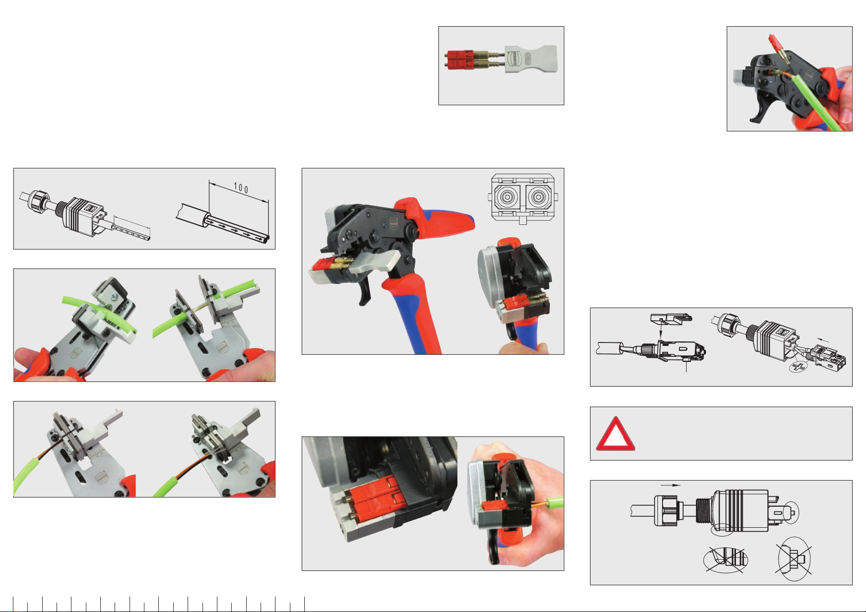
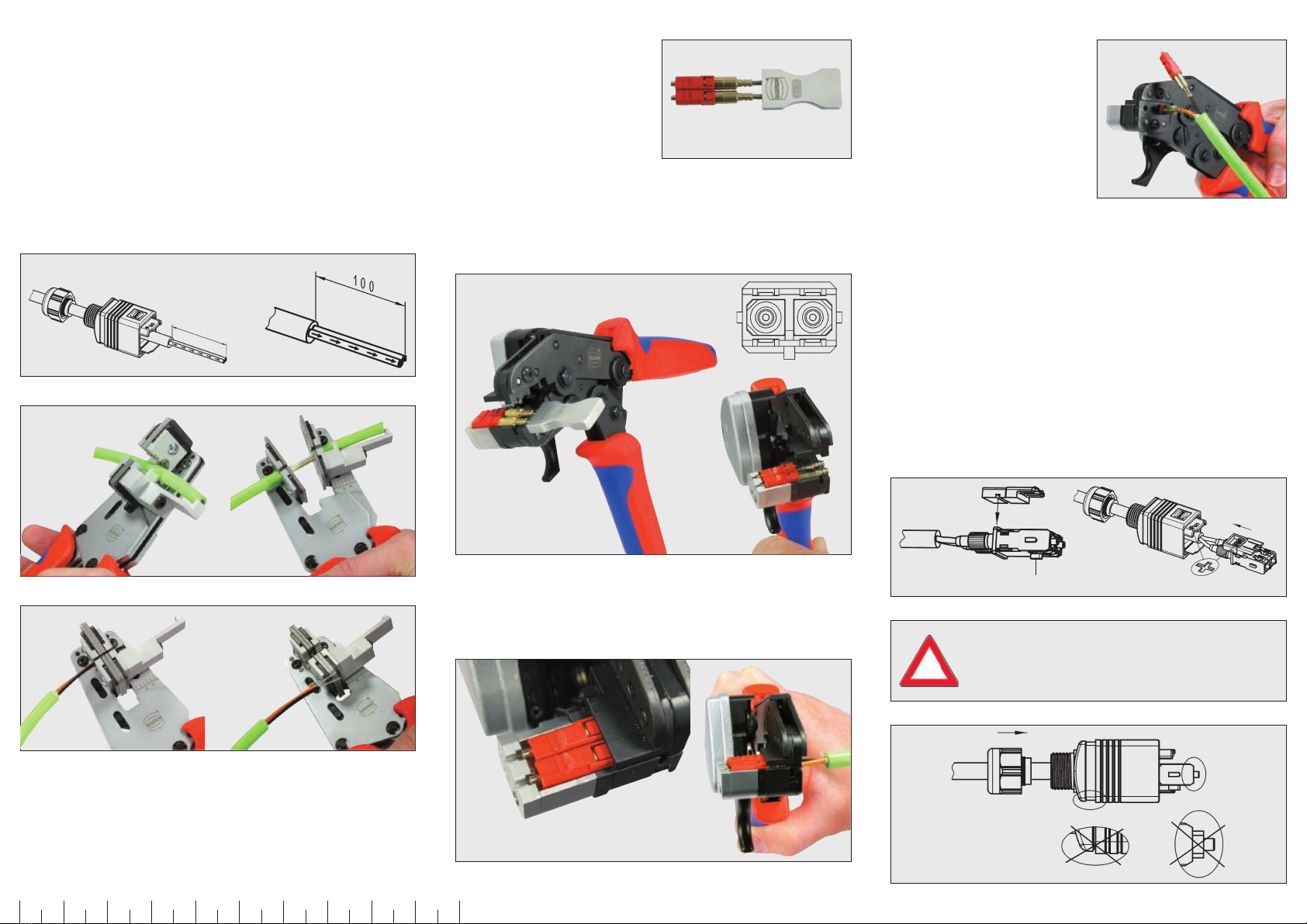
3. Crimpen und Schneiden
Einlegehilfe mit SC Kontak-
ten bestücken, dabei Lage
der SC Kontakte beachten:
gerade Flächen zeigen zuein-
ander.
SC Kontakte mit Einlegehilfe in das Werkzeug einlegen und
Zange in Rastposition drücken, um die Kontakte gegen Her-
ausfallen zu sichern, Einlegehilfe entnehmen.
Abb. 10
Abisolierte Fasern bis zum Anschlag in die SC Kontakte ein-
schieben, so dass die Fasern vorne überstehen. Zange zum
Crimpen bis zum Ausrasten durchdrücken.
A b b . 11
Einsetzen der Einzelkon-
takte zum Schneiden, Lage
beachten: gerade Fläche
zeigt nach unten, Zange zu-
sammendrücken und halten,
Faser an der Ferrulenspitze
Schneiden, danach mit 2.
Ferrule wiederholen.
SC Kontakte in SCRJ Container eindrücken, dabei Rich-
tungspfeile auf Container und POF-Adern (orange/schwarz)
beachten, gerade Flächen der Kontakte zeigen zueinander.
4. Montage IP65/ IP67 Steckverbinder (Abb. 15)
SCRJ Container in Adapterplatte einsetzen. Codiernase
liegt auf gegenüberliegender Seite. Einsatz ins Gehäuse zu-
rückschieben (Symbole beachten) und verrasten. Kabelver-
schraubung mit 3 Nm anziehen.
Abb. 14 Codiernase
Auf richtige Position der SC-Kontakte und des
verschiebbaren Gehäuseoberteils während des
Anziehens der Kabelverschraubung achten.
!
Auf korrekte
Position achten!
Abb. 15
Abb. 9
Abb. 12
010 20 30 40 50 60 70 80 90 100 mm

Order numbers
09 35 000 9915 SCRJ POF tool set
09 35 000 9914 Spare cutter
General information
These tools should only be used if in proper condition and
with proper awareness of safety aspects and hazards. They
should only be used for the purpose as described in the
“instructions for use”.
Purpose
This tool set is designed for cutting, stripping and
terminating fibre-optic cables (POF cables) with a cable
diameter of 2.2 mm and a core fibre diameter of 1.0 mm for
SCRJ type plug connectors.
Transport pin
Prior to first use of the cutter assembly of the
crimp and cutting tool (Fig. 4) the transport
pin (threaded pin) should be released and
removed (see label) using the enclosed Allen
key.
!
Cutter assembly
The cutter assembly can be easily replaced and is available
as a spare part (order number 09 35 000 9914). The cutter
assembly comprises a feed gear with remaining cuts
indicator, round cutter and lever handle.
Each cut turns the cutter by 12° in a clockwise direction
and therefore ensures that the cutting edge is evenly used.
After a fixed number of cuts (set ex-works at 2500) the
cutter is blocked automatically and must be replaced. The
remaining cuts indicator shows the last 150 cuts prior to the
cutter blocking for replacement.
Replacing the cutter assembly
The installation and removal of the cutter assembly is
achieved using the fixing screw (Fig. 12). By undoing the
screw the cutter assembly can be pulled sideways from the
body of the tool.
When installing the cutter assembly please ensure that
before tightening the fixing screw the flat end of the return
spring is located behind the clamp jaws and that the cutter
assembly is in contact with the stop pin.
Then undo the transport pin (threaded pin) using the Allen
key.
Fig. 1
Round
blade
Transport
pin
Remaining
cuts
indicator
Lever
handle
Maintenance and servicing
The stripper and cutting tool must be clean and in proper
service order prior to use. Remove any residues. Joints
should be protected against contamination and dirt.
Always ensure that all bolts are secured by the circlips. The
cutter assembly and in particular the cutting blade must
be protected against damage because otherwise the tool
becomes unserviceable.
When the cutting tool is not required, it should stored clean
and dry. In the case of tool repairs, please consult the
manufacturer.
Replacing the cutter blade is a task for the
manufacturer only.
!
Before replacing the blade the transport pin
(threaded pin) must be tightened using the
Allen key.
!
Fig. 2
Stripper tool
Fig. 3
Kevlar scissors
Fig. 4
Crimp and cutter tool
Fig. 5
Insertion adapter
Order no. 09 35 000 9915/99.00
Version 1.1 – 2017-07
Errors and technical revisions reserved.
HARTING Electronics GmbH
32339 Espelkamp – Germany ENGLISH
Instructions for „Cutting without polishing“
for SCRJ plug connectors with crimp type connection
for polymer-optic fibres (POF)
Instructions for cable terminating
1. Preparing plug connectors and cables
Insert the cable into the stripper (Fig. 2) to the 57 mm stop
and strip the cable sheath in accordance with figures 6 and
7. Using the Kevlar scissors (Fig. 3), cut the exposed filler
and remove the strain relief.
- IP65/IP67: Insert fibre optic cable through assembly
and housing (Fig. 6)
IP65 / IP67
IP20
57
Fig. 6
Fig. 7
Fig. 8
2. Strip the polymer optical fibres
Insert the orange and black individual fibre cores into the
stripper (Fig. 2) up to the 11 mm mark in accordance with
Fig. 8 and strip.
3. Crimping and cutting
Place the SC contacts on
the insertion adapter and
ensure the SC contacts are
in the correct position: flat
surfaces should face each
other.
SC contacts should be placed into the tool using the
insertion adapter and then compress the tool to the first
stop position to prevent the contacts from slipping off;
remove the insertion adapter.
Fig. 10
Insert the stripped fibres to end stop in the SC contacts, so
that the fibres protrude at the front. Compress the tool until
the end position is reached to crimp.
F i g . 11
Insert the individual
contacts ready for cutting;
ensure they are in the
correct position: flat surface
should face downwards.
Compress the tool and hold,
cut the fibre at the tip of the
ferrule and then repeat with
the 2nd ferrule.
Insert the SC contacts in the SCRJ container, observing
the direction arrows on the container and the POF cores
(orange/black); the flat surfaces of the contacts should face
each other.
4. Assembly of IP65/ IP67 plug connectors (Fig. 15)
Insert the SCRJ container in the adapter plate. The coding
nub should be on the opposite side. Slide the insert into
the housing (paying attention to symbols) and lock in place.
Tighten the cable assembly to 3 Nm.
Fig. 14 Coding nub
Ensure correct positioning of the SC contacts
and the movable upper casing when tightening
the cable assembly.
!
Check for
correct positions!
Fig. 15
Fig. 9
Fig. 12
010 20 30 40 50 60 70 80 90 100 mm
This manual suits for next models
1
Table of contents
Languages:
Other HARTING Power Tools manuals


Popular Power Tools manuals by other brands


DeWalt
DeWalt D25501-AR instruction manual

Costway
Costway ULTIMATE FORCE ET1378US user manual

Zeitler
Zeitler EZ100 operating instructions

F.F. Group
F.F. Group GVE 174 N1 PLUS Original instructions

Bosch
Bosch GSH 27 VC Professional Original instructions

Stanley
Stanley Avdel NeoBolt PB2500N Instruction and service manual


