HARTING SCRJ POF User manual

Bestell-Nummern
09 35 000 9913 SCRJ POF Werkzeug-Set
09 35 000 9914 Ersatz-Schneideeinrichtung
Allgemeines
Die Werkzeuge dürfen nur in technisch einwandfreiem Zu-
stand sowie sicherheits- und gefahrenbewusst benutzt
werden und sind nur für den in der Bedienungsanleitung be-
schriebenen Zweck zu verwenden.
Verwendungszweck
Das Werkzeugset wird zum Schneiden, Abisolieren und Kon-
fektionieren von Lichtwellenleiter (POF-Kabel) mit einem
Kabeldurchmesser von 2,2 mm und einem Faserkerndurch-
messern von 1,0 mm für Steckverbinder vom Typ SC-RJ ein-
gesetzt.
Transportsicherung
Vor dem ersten Benutzen der Schneideein-
richtung des Abisolier- und Schneidewerk-
zeugs (Abb. 3) ist die Transportsicherung
(Gewindestift, Abb. 5) mit dem beigelegten In-
nensechskantschlüssel zu lösen bzw. zu ent-
fernen (siehe Etikett).
!
Schneideeinrichtung
Die Schneideeinrichtung ist als Ersatzteil problemlos aus-
tauschbar (Bestell-Nummer 09 35 000 9914). Sie besteht
aus einem Vorschubgetriebe mit Restschnittanzeige, Rund-
messer und Schwenkhebel.
Mit jedem Schnitt wird das Messer um 12° im Uhrzeigersinn
weitergedreht und somit eine gleichmäßige Ausnutzung des
Messerumfangs realisiert.
Nach einer vom Werk festgelegten Anzahl von Schnitten
(1260) blockiert die Schneideeinrichtung automatisch und
muss ausgetauscht werden. Über eine Restschnittanzeige
werden die letzten 150 Schnitte vor dem Blockieren der
Schneideeinrichtung angezeigt.
Austausch der Schneideeinrichtung
Der An- und Abbau der Schneideeinrichtung wird über die
Befestigungsschraube 7 (Abb. B) realisiert. Durch Lösen der
Schraube kann die Schneideeinrichtung seitlich vom Zan-
gengrundkörper abgezogen werden.
Beim Anbau der Schneideeinrichtung ist zu beachten, dass
vor dem Anziehen der Befestigungsschraube das gerade
Ende der Rückholfeder hinter die Klemmbacken der Zange
gebracht wird und die Schneideinrichtung an dem Anschlag-
stift anliegt.
Anschließend ist die Transportsicherung (Gewindestift) mit-
tels Innensechskantschlüssel zu lösen.
Wartung und Instandhaltung
Das Abisolier- und Schneidewerkzeug muss vor Arbeits-
beginn in einem ordnungsgemäßen und sauberen Zustand
sein. Rückstände sind zu entfernen. Die Gelenke sind vor
Verschmutzung zu schützen.
Es ist darauf zu achten, dass alle Bolzen durch Sicherungs-
ringe gesichert sind. Die Schneideeinrichtung und insbeson-
dere das Schneidmesser sind vor Beschädigung zu schüt-
zen, da diese zur Unbrauchbarkeit oder Zange führen.
Wird die Schneidzange nicht mehr benötigt, sollte sie tro-
cken und sauber gelagert werden. Bei erforderlichen Repa-
raturen an der Zange sollte der Zangenhersteller konsultiert
werden.
Das Auswechseln des Schneidmessers der
Schneideeinrichtung kann nur vom Hersteller
vorgenommen werden.
!
Vor Auswechseln des Schneidmessers ist
immer die Transportsicherung (Gewindestift)
mittels Innensechskantschlüssel anzuziehen.
!
Abb. 1
Abmantelwerkzeug
Abb. 2
Kevlarschere
Abb. 3
Abisolier- und Schneidewerkzeug
Abb. 4
Positionierungs-
hilfe
Best.-Nr. 09 35 000 9913/99.00
Version 1.3 – 2015-07
Irrtum und technische Änderungen vorbehalten
HARTING Electronics GmbH
32339 Espelkamp DEUTSCH
Bedienungsanleitung „Schneiden ohne Polieren“
für SCRJ-Steckerverbinder mit Schnellanschlusstechnik
für polymeroptische Fasern (POF)
Abb. 5
Rund-
messer
Transport-
sicherung
Rest-
schnitt-
anzeige
Schwenk-
hebel
HARTING Electronics GmbH | MA 09350009913_99_00 Rev.B | 2016-06-10 | Final Release | 500000105456 | ELLERMANN | Page 1/4
Ã
À
 Á
Å
Æ
Ä
SCRJ Container
IP65 / IP67 IP20
57
SCRJ Container
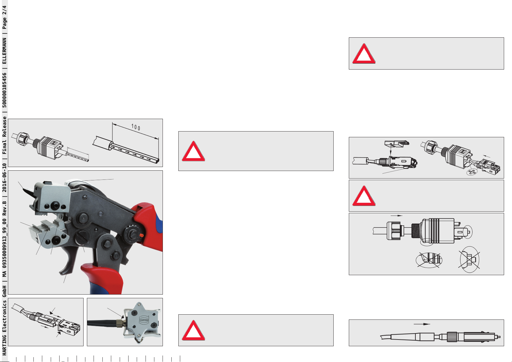
010 20 30 40 50 60 70 80 90 100 mm
Konfektionierungsanleitung
1. Vorbereitung Steckverbinder und Kabel
Kabelmantel gemäß Abb. A mit Abmantelwerkzeug (Abb. 1)
entfernen. Mit Kevlarschere (Abb. 2) das freigelegte Füll-
material und die Zugentlasung abschneiden. Ggf. Einzelader
mit Kabelschneider auf Arbeitslänge 57 mm bzw. 100 mm
schneiden (Messerblock 1, Abb. B).
– IP20: Knickschutztüllen über die Einzeladern
ziehen (Abb. A)
– IP65/IP67: LWL-Kabel durch Verschraubung
und Gehäuse einführen (Abb. A)
2. Schneiden der polymeroptischen Fasern
Beide LWL-Einzelader in Führungsnut 2 (Abb. B) einlegen, Fa-
serende bis zum Ende der Auflage schieben. Zange bis Fest-
anschlag schließen und halten. Mit Zeigefinger Schwenk-
hebel 6 (Abb. B) bis zum Anschlag nach hinten ziehen, ggf.
dabei mit Druck auf Schneideeinrichtung 5 (Abb. B) mit
anderer Hand unterstützen. Nach dem Schnitt Schneide-
einrichtung in Ausgangsposition bringen, Zange öffnen und
Kabel entnehmen.
3. Abisolieren der polymeroptischen Fasern
LWL-Einzelader zum Abisolieren in Kabelführungsnut 3 (Abb.
B) bis zur Markierung (11 mm) einlegen.
Bei Kabeln mit verseilten Einzeladern (z. B.
Trailingkabel) müssen die Adern einzeln ab-
isoliert werden. Parallel geführte Einzeladern
können gleichzeitig abisoliert werden.
!
Zange bis Festanschlag schließen und halten. Betätigungs-
hebel 4 (Abb. B) schließen und LWL Einzelader abisolieren.
Anschließend Betätigungshebel wieder in Ausgangsposition
bringen, Zange öffnen und Kabel entnehmen.
4. Konfektionierung der SC POF Kontakte
SC POF Kontakte in SCRJ-Container einsetzen (Abb. C).
Dabei die abisolierten und geschnittenen Fasern entspre-
chend der Richtungspfeile in den SC Kontakten vorpositio-
nieren.
Die Positonierungshilfe (Abb. 4) dient dazu, die Fasern bün-
dig mit der Ferrule zu positionieren. Positionierungshilfe
durch Betätigen der seitlichen Arretierungshebel öffnen und
SCRJ Container einlegen (Abb. D).
Es ist darauf zu achten, dass der SCRJ Contai-
ner durch die Fixierungsklammern vollständig
in die Positionierungshilfe gedrückt wird.
!
Die Fasern einzeln mit leichtem Druck gegen den Anschlag
drücken und Rändelschraube der SC-Kontakte anziehen.
Die Fasern dürfen nicht zu sehr angedrückt
werden, da sich diese sonst durchbiegen/stre-
cken und es zu einem Faserüberstand kommt.
!
5. Montage IP65/IP67 Steckverbinder (Abb. E)
SCRJ Container in Adapterplatte einsetzen. Codiernase
liegt auf gegenüberliegender Seite. Einsatz ins Gehäuse zu-
rückschieben (Symbole beachten) und verrasten. Kabelver-
schraubung mit 3 Nm anziehen.
Abb. E
Codiernase
Auf richtige Position der SC-Kontakte und des
verschiebbaren Gehäuseoberteils während des
Anziehens der Kabelverschraubung achten.
!
Auf korrekte
Position achten!
Abb. F
6. Montage IP20 Steckverbinder (Abb. G)
Knickschutztüllen auf die SC-Kontakte stecken.
Abb. G
Abb. B
SC POF Kontakte
Abb. C Abb. D
Abb. A
HARTING Electronics GmbH | MA 09350009913_99_00 Rev.B | 2016-06-10 | Final Release | 500000105456 | ELLERMANN | Page 2/4

Order numbers
09 35 000 9913 SCRJ POF Tool Set
09 35 000 9914 Replacement Cutting Unit
General
The tools may be used only in technically flawless condition
as well as with awareness of safety and hazard aspects;
they shall be used only for the purpose outlined in the
operating instructions.
Intended use
The tool set is used for the cutting, stripping and assembly
of optical waveguides (POF cables) with a cable diameter of
2.2 mm and a fibre core diameter of 1.0 mm for type SC-RJ
PushPull connectors.
Transport guard
Prior to the first use of the cutting unit of
the stripping and cutting tool (Fig. 3) the
transport guard (threaded pin, Fig. 5) must
be unscrewed or removed with the enclosed
hexagon socket key (see label).
!
Cutting unit
The cutting unit can be easily replaced as spare part (order
number 09 35 000 9914). It consists of a feeding gear with
residual cut indicator, round blade and turning lever.
With each cut the blade is rotated further clockwise by
12° thus realising the uniform utilisation of the blade
circumference.
After a number of cuts (1260) defined by the factory the
cutting unit blocks automatically and must be replaced. A
residual cut indicator indicates the last 150 cuts before the
cutting unit blocks.
Replacing the cutting unit
The cutting unit is mounted and removed via the mounting
screw 7 (Fig. B). The cutting unit can be pulled off on the
side from the main body of the tool by loosening the screw.
Care must be taken when mounting the cutting unit that
before tightening the mounting screw the straight end of the
return spring is positioned behind the clamping jaws of the
tool and the cutting unit rests against the stop pin.
After this, the transport guard (threaded pin) must be loosed
with a hexagon socket key.
Maintenance and repair
The stripping and cutting tool must be in proper and clean
condition before beginning to work. Residues need to be
removed. The joints need to be protected against dirt build-
up.
Care must be taken that all pins are secured with locking
rings. The cutting unit and especially the cutting blade must
be protected against damage since this would render the
tool unusable.
The cutting tool should be stored in a dry and clean
place when not needed. The tool manufacturer should be
consulted if any repair on the tool is required.
The replacement of the cutting blade of
the cutting unit can only be handled by the
manufacturer.
!
Before replacing the blade the transport pin
(threaded pin) must be tightened using the
Allen key.
!
Fig. 1
Stripping tool
Fig. 2
Kevlar cutters
Fig. 3
Stripping and cutting tool
Fig. 4
Positioning aid
Order No. 09 35 000 9913/99.00
Version 1.3 – 2015-07
Error and technical changes reserved
Operating instructions “Cutting without Polishing”
for SCRJ PushPull connectors with fast termination
technology for polymer-optical fibres (POF)
Fig. 5
Round
blade
Transport
guard
Remaining
cut
indicator
Turning
lever
HARTING Electronics GmbH
32339 Espelkamp – Germany ENGLISH
HARTING Electronics GmbH | MA 09350009913_99_00 Rev.B | 2016-06-10 | Final Release | 500000105456 | ELLERMANN | Page 3/4

Ã
À
 Á
Å
Æ
Ä
SCRJ Container
IP65 / IP67 IP20
57
SCRJ Container
010 20 30 40 50 60 70 80 90 100 mm
Assembly instructions
1. Preparing the PushPull connector and cable
Remove the cable sheath according to Fig. A with the
stripping tool (Fig. 1). Use the Kevlar cutters (Fig. 2) to cut off
the exposed filler material and the strain relief. If necessary,
cut the individual strand with the cable cutter to a working
length of 57 mm or 100 mm. (blade block 1, Fig. B)
– IP20: Pull antikinking grommets over the single
strands (Fig. A)
– IP65/IP67:
Guide and insert the optical waveguide
cable through the gland and housing (Fig. A)
2. Cutting the polymer optical fibres
Insert both individual optical waveguide strands into the
guide groove 2 (Fig. B); push the end of the fibre to the end
of the support. Close the tool against the fixed stop and
hold. Pull the turning lever 6 (Fig. B) back with the index
finger against the stop; apply pressure to the cutting unit
5 (Fig. B) by supporting it with the other hand, if necessary.
Move the cutting unit to the starting position after cutting,
open the tool and remove the cable.
3. Stripping the polymer optical fibres
Insert the individual optical waveguide strand into the cable
guide groove 3 (Fig. B) up to the mark (11 mm).
For cables with stranded wires (e.g.
trailing cables) the wires must be stripped
individually. Parallel single strands can be
stripped at the same time.
!
Close the tool against the fixed stop and hold. Close the
operating lever 4 (Fig. B) and strip the individual optical
waveguide strand. Now move the operating lever back to
the starting position, open the tool and remove the cable.
4. Assembly of the SC POF contacts
Insert the SC POF contacts into the SCRJ container. (Fig.
C) Preposition the stripped and cut fibres according to the
directional arrows in the SC contacts.
The positioning aid (Fig. 4) is used to position the fibres
flush with the ferrule. Open the positioning aid by operating
the locking levers on the side and insert the SCRJ container
(Fig. D).
Care must be taken that the SCRJ container
is fully pressed into the positioning aid by the
fixing clamp.
!
Push the fibres individually with slight pressure against the
stop and tighten the thumb screw of the SC contacts.
The fibres must not be pushed down too
much since they will otherwise bend/stretch
and the fibre will protrude.
!
5. Assembly IP65 / IP67 PushPull connectors (Fig. E)
Insert SCRJ container into the adapter plate. The coding
lug lies on the opposite side. Pull the insert back into the
housing (note the symbols) and engage. Tighten the cable
gland with 3 Nm.
Fig. E
coding lug
Observe the correct position of the SC
contacts and the movable housing top while
tightening the cable gland.
!
Observe correct
position!
Fig. F
6. Assembly of IP20 PushPull connectors (Fig. G)
Push the antikinking grommets onto the SC contacts.
Fig. G
Fig. B
SC POF Contacts
Fig. C Fig. D
Fig. A
HARTING Electronics GmbH | MA 09350009913_99_00 Rev.B | 2016-06-10 | Final Release | 500000105456 | ELLERMANN | Page 4/4
This manual suits for next models
1
Table of contents
Languages:
Other HARTING Power Tools manuals


Popular Power Tools manuals by other brands

EINHELL
EINHELL TE-MG 200 CE Original operating instructions

Bosch
Bosch 1944LCD Operating/safety instructions

Loctite
Loctite Zeta 7740 Operation manual

Virtual industries
Virtual industries SMD-VAC-HF Operating instructions and specifications

CLAS
CLAS OP 1411 manual

Star Tec PRODUCTS
Star Tec PRODUCTS VACUUM - UNIT ST 902 operating manual


