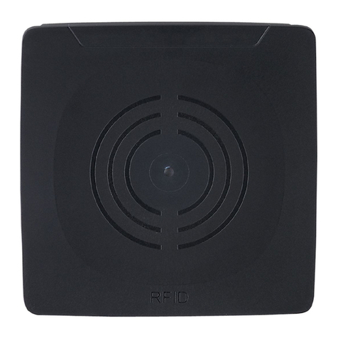
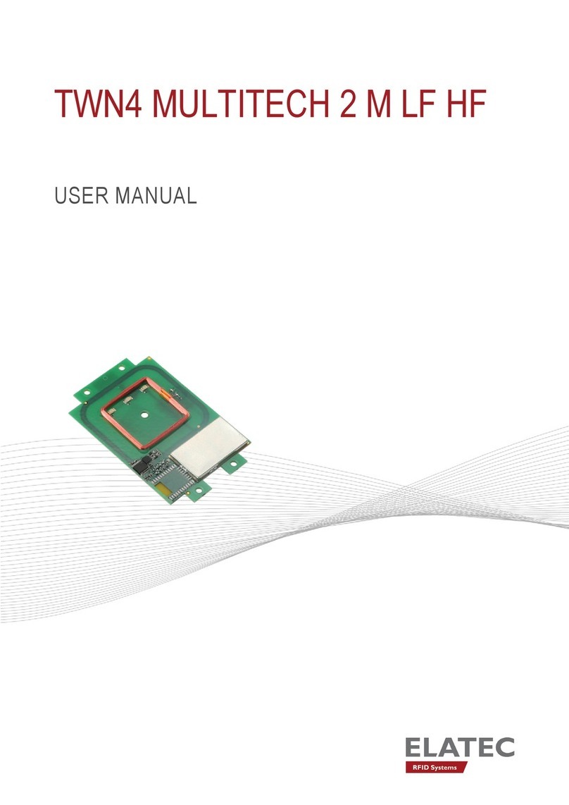
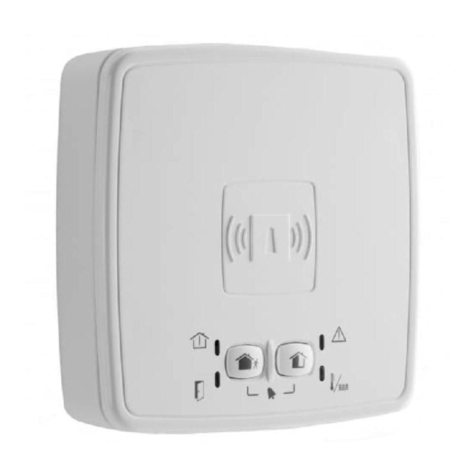
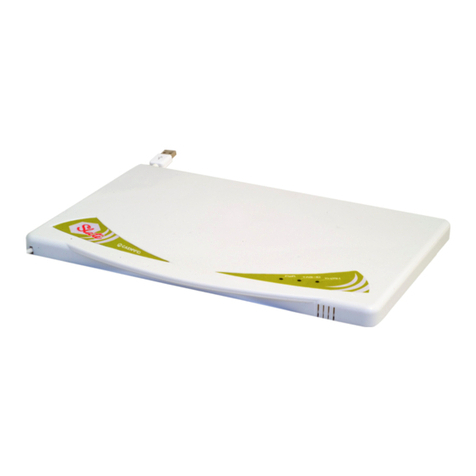
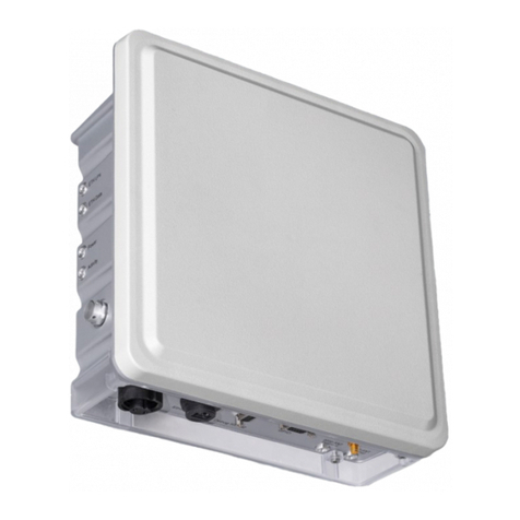
HARTING Ha-VIS RFID RF-R400 User guide

HARTING Ha-VIS RFID RF-R400
System Manual

2HARTING IT Software Development GmbH & Co. KG
Ha-VIS RFID RF-R400 – System Manual
All brand and product names are trademarks or registered trademarks of the owner concerned.
1st Edition 2017, revised 02/17
© HARTING IT Software Development GmbH & Co. KG, Germany
Author: HARTING
Editor: HARTING
All rights are reserved, including those of the translation.
No part of this manual may be reproduced in any form (print, photocopy, microlm or any
other process), processed, duplicated or distributed by means of electronic systems without
the written permission of HARTING IT Software Development GmbH & Co. KG, Espelkamp,
Germany.
Subject to alterations without notice.
Printed on bleached cellulose. 100% free from chlorine and acid.

3
Ha-VIS RFID RF-R400 – System Manual
Contents
Contents
1. About this manual.............................................................................................................................................. 6
1.1 Subject ................................................................................................................................................................6
1.2 Audience .............................................................................................................................................................6
1.3 Before you begin.................................................................................................................................................6
1.4 General informations regarding this document ................................................................................................... 6
1.5 Ha-VIS RFID documentation...............................................................................................................................6
1.5.1 Explanation of the symbols ...................................................................................................................... 7
1.5.2 Typographical conventions....................................................................................................................... 7
1.6 Safety Instructions / Warnings - Read before start-up! ....................................................................................... 7
2. Revision History of Document.......................................................................................................................... 9
3. Abbreviations ................................................................................................................................................... 10
4. Introduction ...................................................................................................................................................... 11
4.1 The UHF Long Range Readers Ha-VIS RFID RF-R400................................................................................... 11
5. Data Transmission between Ha-VIS RFID RF-R400 and Host...................................................................... 12
5.1 Conguration Commands and Control Commands .......................................................................................... 12
5.2 Host Commands ...............................................................................................................................................12
5.3 Buffered Read Mode.........................................................................................................................................13
5.4 Notication Mode .............................................................................................................................................. 14
5.5 Scan Mode........................................................................................................................................................15
5.5.1 Scan Mode via asynchronous interface: ................................................................................................15
6. Interface ............................................................................................................................................................ 17
6.1 Characteristics of TCP/IP protocol ....................................................................................................................17
6.2 Serial Data Format and Protocol Frames..........................................................................................................17
6.3 CRC16 Calculation Algorithm............................................................................................................................19
7. Conguration Parameters ............................................................................................................................... 20
7.1 CFG0: Passwords.............................................................................................................................................21
7.2 CFG1: Interface and Mode................................................................................................................................22
7.3 CFG2: Inputs / Outputs ....................................................................................................................................25
7.4 CFG3: RF-Interface ..........................................................................................................................................27
7.5 CFG4: Transponder Parameters.......................................................................................................................33
7.6 CFG5: Anticollision............................................................................................................................................ 34
7.7 CFG6 .. 8: Reserved .........................................................................................................................................35
7.8 CFG9: Input / Output II (Assignment – output to antenna read event) ............................................................. 36
7.9 CFG10: Trigger ................................................................................................................................................37
7.10 CFG11: Read Mode – Read Data..................................................................................................................... 39
7.11 CFG12: Read Mode - Filter............................................................................................................................... 45
7.12 CFG13 Scan Mode ........................................................................................................................................... 47
7.13 CFG14: Reserved .............................................................................................................................................50
7.14 CFG15: Antenna Multiplexing I .........................................................................................................................51
7.15 CFG16: Persistence Reset ..............................................................................................................................52
7.16 CFG17 .. 19: Reserved .....................................................................................................................................53

4HARTING IT Software Development GmbH & Co. KG
Ha-VIS RFID RF-R400 – System Manual
7.17 CFG20: RF-Parameter .....................................................................................................................................53
7.18 CFG22 .. 27: Selection masks for EPC Gen 2.................................................................................................. 55
7.19 CFG28 .. 32: Reserved .....................................................................................................................................59
7.20 CFG33 .. 34: LAN-Hostname............................................................................................................................59
7.21 CFG35 .. 39: Reserved .....................................................................................................................................60
7.22 CFG40: LAN Settings, Part 1 ...........................................................................................................................60
7.23 CFG41: LAN Settings, Part 2 ...........................................................................................................................60
7.24 CFG49: Notication Channel ........................................................................................................................... 62
7.25 CFG63: Customer Parameter ...........................................................................................................................63
8. Protocols for Reader Conguration ............................................................................................................... 64
8.1 [0x85] Set System Timer...................................................................................................................................64
8.2 [0x86] Get System Timer...................................................................................................................................64
8.3 [0x87] Set System Time and Date.....................................................................................................................65
8.4 [0x88] Get System Time and Date ...................................................................................................................65
8.5 [0x80] Read Conguration ................................................................................................................................ 66
8.6 [0x81] Write Conguration.................................................................................................................................67
8.7 [0x83] Reset Conguration................................................................................................................................67
9. Protocols for Reader Control.......................................................................................................................... 69
9.1 [0x52] Baud Rate Detection .............................................................................................................................69
9.2 [0x63] RF Controller Reset ...............................................................................................................................69
9.3 [0x64] System Reset ........................................................................................................................................69
9.4 [0x66] Get Reader Info...................................................................................................................................... 70
9.4.1 MODE = 0x00 (RFC Controller Firmware) ............................................................................................71
9.4.2 Mode = 0x10 (Hardware Information) ................................................................................................... 71
9.4.3 Mode = 0x40 .. 0x41 (Conguration Information for read and write) ..................................................... 73
9.4.4 Mode = 0x50 .. 0x53 (LAN LConguration) ........................................................................................... 73
9.4.5 Mode = 0x60 (I/O-Capabilities) ............................................................................................................. 74
9.4.6 Mode = 0x80 (Device Information) ........................................................................................................ 75
9.4.7 Mode = 0xFF (All Info Records) ............................................................................................................. 75
9.5 [0x69] RF Reset ................................................................................................................................................76
9.6 [0x6A] RF Output ON/OFF................................................................................................................................ 76
9.7 [0x6E] Reader Diagnostic ................................................................................................................................. 77
9.7.1 MODE = 0x01......................................................................................................................................... 78
9.7.2 MODE = 0x04......................................................................................................................................... 79
9.7.3 MODE = 0x05 ........................................................................................................................................ 79
9.7.4 MODE = 0x20......................................................................................................................................... 80
9.7.5 MODE = 0xFF: READ ALL ..................................................................................................................... 80
9.8 [0x72] Set Output ..............................................................................................................................................80
9.8.1 Set Output Examples ............................................................................................................................. 81
9.9 [0x74] Get Input ................................................................................................................................................82
9.10 [0x8D] Lock Region........................................................................................................................................... 82
9.11 [0xA0] Reader-Login .........................................................................................................................................83
9.12 [0xA3] Write AES Reader Keys.........................................................................................................................83
9.13 [0xAD] Write Reader Authentication Key ..........................................................................................................84
10. Protocols for Host Commands ....................................................................................................................... 86
10.1 [0xB0] Host commands ....................................................................................................................................86
10.1.1 [0x01] Inventory...................................................................................................................................... 86
10.1.2 [0x23] Read Multiple Blocks ................................................................................................................... 88

5
Ha-VIS RFID RF-R400 – System Manual
10.1.3 [0x24] Write Multiple Blocks ................................................................................................................... 91
10.2 [0xB3] Host commands for EPC Transponders ................................................................................................ 93
10.2.1 [0x18] Kill................................................................................................................................................ 93
10.2.2 :[0x22] Lock ............................................................................................................................................ 94
10.2.3 [0x25] BlockPermalock........................................................................................................................... 95
10.2.4 [0x26] Read Permalock Status............................................................................................................... 97
10.2.5 [0x30] Untraceable ................................................................................................................................. 99
10.2.6 [0x31] Authenticate............................................................................................................................... 101
10.3 Supported host commands for transponders.................................................................................................. 103
10.3.1 EPC class 1 Gen 2 ............................................................................................................................... 103
11. Protocols for Buffered Read Mode and Notication Mode ........................................................................ 104
11.1 The Buffered Read Mode Procedure ..............................................................................................................104
11.2 The Notication Mode Procedure.................................................................................................................... 105
11.3 Transponder Access in the Buffered Read Mode and Notication Mode........................................................ 105
11.4 [0x22] Read Buffer ..........................................................................................................................................106
11.5 [0x31] Read Data Buffer Info...........................................................................................................................109
11.6 [0x32] Clear Data Buffer..................................................................................................................................109
11.7 [0x33] Initialize Buffer...................................................................................................................................... 110
12. ANNEX..............................................................................................................................................................111
12.1 ANNEX A: Codes of Transponder Types .........................................................................................................111
12.2 ANNEX B: Codes of Identier Data Bytes (IDDT)............................................................................................111
12.3 ANNEX C: Index of Status Bytes .....................................................................................................................111

6HARTING IT Software Development GmbH & Co. KG
Ha-VIS RFID RF-R400 – System Manual
1. About this manual
1.1 Subject
This book describes the conguration of the RFID Reader Ha-VIS RF-R400 from HARTING.
The instructions given in this manual are based on advantageous boundary conditions.
HARTING does not give any guarantee promise for perfect function in cross environments and
does not give any guarantee for the functionality of the complete system which incorporates the
subject of this document.
HARTING call explicit attention that devices which are subject of this document are not
designed with components and testing methods for a level of reliability suitable for use in or in
connection with surgical implants or as critical components in any life support systems whose
failure to perform can reasonably be expected to cause signicant injury to a human. To avoid
damage, injury, or death, the user or application designer must take reasonably prudent steps
to avoid system failures.
HARTING assumes no responsibility for the use of any information contained in this manual
and makes no representation that they are free of patent infringement. HARTING does not
convey any license under its patent rights nor the rights of others.
Ha-VIS is a registered trademark of HARTING.
1.2 Audience
This book is intended for application developers who want to develop applications with Ha-VIS
RF-R400.
1.3 Before you begin
This book assumes familiarity with RFID.
1.4 General informations regarding this document
• The sign „@“ indicates extensions or changes of this manual compared with the former
issue.
• If bits within one byte are lled with „-“, these bit spaces are reserved for future extensions
or for internal testing- and manufacturing-functions. These bit spaces must not be changed,
as this may cause faulty operation of the reader.
• The following gure formats are used:
• 0...9: for decimal gures
• 0x00...0xFF: for hexadecimal gures
• b0...1 for binary gures.
• The hexadecimal value in brackets „[ ]“ marks a control byte (command).
1.5 Ha-VIS RFID documentation
This book is part of the Ha-VIS RFID documentation set. Visit http://www.HARTING-RFID.com
to obtain the latest version of the Ha-VIS RFID documentation and additional information and
resources.

7
Ha-VIS RFID RF-R400 – System Manual
About this manual
1.5.1 Explanation of the symbols
The following symbols are used in this software guide:
CAUTION
This text describes warning notes that indicate a low-level source of danger. If not avoided,
human damage to property may result.
ATTENTION
This text describes warning notes that indicate a low-level source of danger. If not avoided,
damage to property may result.
Note
This symbol describes general notes supplying important information concerning one or more
operating steps. It also provides references to further information supplied within this manual.
1.5.2 Typographical conventions
Format Meaning Example
blue (in normal text) Link to other chapters Link to
external web pages
Ha-VIS RFID - Getting Started Guide http://
www.HARTING.com
italic blue Paths; folder c:/Programme/Ha-VIS/RFID
bold Names of modules and other
important items
EventType
bold italic Names of characteristics or
similarly
OnApplicationMessage
1.6 Safety Instructions / Warnings - Read before start-up!
• The device may only be used for the purpose intended by the manufacturer
• When installing the device in areas covered under US 47 CFR Part 15 a minimum
separation of 25 cm between antenna and the human body must be maintained.
• The operation manual should be kept readily available at all times for each user.
• Unauthorized changes and the use of spare parts and additional devices which have not
been sold or recommended by the manufacturer may cause re, electric shocks or injuries.
Such unauthorized measures shall exclude the manufacturer from any liability.
• The liability-prescriptions of the manufacturer in the issue valid at the time of purchase are
valid for the device. The manufacturer shall not be held legally responsible for inaccuracies,
errors, or omissions in the manual or automatically set parameters for a device or for an
incorrect application of a device.
• Repairs may only be undertaken by the manufacturer.
• Installation, operation, and maintenance procedures should only be carried out by qualied
personnel.

8HARTING IT Software Development GmbH & Co. KG
Ha-VIS RFID RF-R400 – System Manual
• Use of the device and its installation must be in accordance with national legal requirements
and local electrical codes .
• When working on devices the valid safety regulations must be observed.
WARNING
Special advice for wearers of cardiac pacemakers:
Although this device doesn‘t exceed the valid limits for electromagnetic elds you should keep
a minimum distance of 25 cm between the device and your cardiac pacemaker and not stay in
the immediate proximity of the device’s antenna for any length of time.
The Ha-VIS RF-R400 must only be operated with the approved frequency adjustment of the
respective coun-try of deployment.
Observe before beginning with installation procedures
• In accordance with EN 50 110-1 /-2 (VDE 0105 Part 100), qualied personnel only
are allowed to carry out transport, installation, commissioning and maintenance tasks.
Guidelines contained in IEC 60 364 and HD 384 (DIN VDE 0100) as well as national
accident prevention regulations must be adhered to.
• Install connection and signal wires ensuring that the bus communication is not impaired by
inductive or capacitive interferences.
• The electrical installation must be carried out in accordance with the relevant regulations
and standards (protective earth connection, wire cross-sections and so forth).
• Ensure correct polarity when connecting the supply.

9
Ha-VIS RFID RF-R400 – System Manual
Revision History of Document
2. Revision History of Document
Revision Date Page Description
0e 26.01.2017 Initial revision

10 HARTING IT Software Development GmbH & Co. KG
Ha-VIS RFID RF-R400 – System Manual
3. Abbreviations
ADR Address
ASK Amplitude Shift Keying
CB Cong Block
CFG Conguration Parameter Block
CRC Cyclic Redundancy Check
DB Data Block
DIP Dual Inline Plastic
DRM Dense Reader Mode
FIFO First in First out
frq Frequency
FSK Frequency Shift Keying
h Hour
Hz Hertz
ID Identication
IDD Identier Data
IN Input
LEN Length
LOC Location
LSB Least Signicant Byte
min Minutes
ms Milliseconds
MSB Most Signicant Byte
N Number
OUT Output
R/W Read / Write Access
RD Read
REL Relay
RF Radio Frequency
RSSI Received Signal Strength Indicator
RTC Real Time Clock
TAB Table
TR Transponder
TS Timeslot
UID Unique Identier (read only Serial Number)
WO Write Only Access
WR Write

11
Ha-VIS RFID RF-R400 – System Manual
Introduction
4. Introduction
4.1 The UHF Long Range Readers Ha-VIS RFID RF-R400
The Ha-VIS RFID RF-R400 is a Long Range Reader version of the UHF product line.
The RF-R400 closes the gap between the RF-R500 high performance long range readers and
the RF-R3x0 mid range reader family. It has the following key features:
• Low noise transmitter architecture
• High sensitivity receiver increases the tag detection range so that transponders can be read
over the entire power up, eld strength area.
• Reader protection against various fault conditions as e.g. antenna shortcut, antenna
mismatching and electrostatic discharge.
• Tough, solid aluminium die case housing for rough environments.
• Quick installation due to easy access to the interfaces and antenna ports.
• Indication of read events via 4 separate reading point LEDs.
• Various I/Os suit industrial needs
• Robust M12 and M8 connectors
• following the EN50155
• very good temperature operating range
The base set of commands and features are compatible with the commands used throughout
the product line. The conguration possibilities of the Ha-VIS RFID RF-R400 make it easy to
adapt the reader to a wide range of applications by software and hardware congurations.
The reader has three hardware interface ports: Ethernet, RS232 and USB. Furthermore, the
reader has digital I/O’s for direct control of various trigger possibilities and various outputs for a
direct control of several indi-cators.

12 HARTING IT Software Development GmbH & Co. KG
Ha-VIS RFID RF-R400 – System Manual
5. Data Transmission between Ha-VIS RFID RF-R400 and Host
Six different ways of data transmission between RF-R400 and host (terminal, PC) are possible.
The Host Commands, Buffered Read Mode, Scan Mode and Notication Mode are used
for the data exchange between transponder and host, whereas the Conguration Commands
and the Reader Control Commands serves for adapting the reader parameters to the
individual range of applications. The following chart shows which method of data transmission
is supported by which interface:
Interface
RS232 LAN USB*
Conguration Commands PPP
Reader Control Commands PPP
Host Commands PPP
Buffered Read Mode PPP
Scan Mode PO O
Notication Mode OPO
*just for testing not recommended for real applications
5.1 Conguration Commands and Control Commands
This method of data transmission is used for Reader conguration and the diagnosis via the
different Hardware Interfaces of the reader.
The reader-conguration parameters will be stored in the Reader memory. To store the current
conguration during a power down of the reader the reader-Conguration has to be stored in
the EEPROM. After power up the reader reads the conguration out of the EEPROM.
The reader control is immediately processed and the response from the Reader contains status
or data information of the control command.
Host (Terminal / PC / ....) Reader
parameter- / control command àparameter received and stored / control
command processed
yes no
ßstatus /
data
ßerror status
5.2 Host Commands
The host commands provide the exchange of data between a host and transponders via the
reader as long as the transponder remains in the detection range of the reader.
Note
During the writing of data to a transponder, it must be ensured that the transponder is located
within the detection range of the reader for the duration of the entire process. If the transponder
is removed from detection range of the reader during a writing process, this will cause a loss of
data.

13
Ha-VIS RFID RF-R400 – System Manual
Data Transmission between Ha-VIS RFID RF-R400 and Host
The reader to transponder addressing mode:
Addressed mode:
Before reading or writing data in addressed mode, the UID of the transponder has to be known.
This is executed by sending the protocol 10.1.1 [0x01] Inventory. If a transponder is located
within the detection range of the reader at that time, it answers with its UID. For all following
read- / write orders the transponder must be addressed with its correct UID. The following chart
will show the necessary steps for the communication with a transponder in addressed mode:
Host (Terminal / PC / ....) Reader
Inventory to get the UID àtransponder in antenna eld?
yes no
ß
status /
number of transponders / UID
ßstatus =
no transponder
read data from transponder with UID àtransponder with correct UID in antenna eld?
yes no
ßstatus /
transponder read data
ßstatus =
no transponder in reader eld
write data to transponder with UID àtransponder with correct UID in antenna eld?
yes no
ßOK status
ßstatus =
no transponder in reader eld
5.3 Buffered Read Mode
The Buffered Read Mode is a high level operating mode to detect transponders which are
within the detection range of the reader. This operation mode processes all transponder read
data and lter operations to make the user interface transparent to transponder data and to
minimize data transfers between reader and host. There are only three commands used to
control Buffered Read Mode.
In this operating mode the reader automatically selects transponders which are within the
detection range of the reader and reads their requested data. The read transponder data is
stored in a ‘FIFO’ organized data buffer. Up to 1700 can be stored into the buffer. In case of
power down the buffer will be initialized and all datasets get lost.
The sampled transponder data can be read with the 11.4 [0x22] Read Buffer command. This
command always reads the rst available data sets from the data buffer. However data already
read have to be deleted with the 11.6 [0x32] Clear Data Buffer command before the next data
sets in the data buffer can be reached with the read command.
If the Buffered Read Mode is enabled in the 7.2 CFG1: Interface and Mode conguration block
the reader immediately starts sampling transponder data after power up. The Buffered Read
Mode can be reinitialized with the 11.7 [0x33] Initialize Buffer command.
If turned to Buffered Read Mode the reader answers every valid message with data- or status-
protocol. The answer includes the control byte which has been received by the reader.

14 HARTING IT Software Development GmbH & Co. KG
Ha-VIS RFID RF-R400 – System Manual
Host (Terminal / PC / ....) Reader
read data àTransponder data in data buffer?
yes no
ß
status /
data protocol
ßstatus = no valid data
clear data àTransponder data read?
yes no
ßOK status
ßstatus = no valid data
Note
Only read operations are available with the Buffered Read Mode.
5.4 Notication Mode
The Notication Mode is an extended option of the Buffered Read Mode: queued transponder
data and optionally Input / status events are notied automatically and asynchronously to a
host with the 11. Protocols for Buffered Read Mode and Notification Mode response protocol.
The destination address and the notication conditions can be set in 7.24 CFG49: Notification
Channel conguration block. In general, the notication channel can be used simultaneously
with the host interface.
In difference to the Buffered Read Mode procedure, a notication is normally not acknowledged
by the host. Thus, the deletion of the transferred data with the 11.6 [0x32] Clear Data Buffer
command is not necessary. As an option, the acknowledgement can be enabled to synchronize
the notications with the host to prevent notication overow in the host application.
The notication message format depends on trigger settings in 7.9 CFG10: Trigger and settings
for the read mode in 7.10 CFG11: Read Mode – Read Data and 7.11 CFG12: Read Mode -
Filter as well as settings for the notication trigger in 7.24 CFG49: Notification Channel. The
following table lists the message formats:
Notication Trigger: continuous or time-triggered
Input/Status Event Data Event
Read Trigger disabled Input/Status and Data Events are notied together in one or multiple
messages.
The message format depends on settings in TR-DATA of CFG11.
Read Trigger enabled Notication separately and
immediately, if in:
CFG11: IN ag in TR-DATA2 is set
and
CFG12: ag is set for input and/or
status to be observed
Notication shortly after notication
of input/status event.
The message format depends on
settings in TR-DATA of CFG11.
Note
One notication can contain more than one input/status event, if multiple events occur at the
same time.

15
Ha-VIS RFID RF-R400 – System Manual
Data Transmission between Ha-VIS RFID RF-R400 and Host
Notication Trigger: host-triggered
Input/Status Event Data Event
Independent of Read Trigger Input/Status and Data Events are notied together in one message. The
notication is activated by command [0x34] Force Notify Trigger.
The message format depends on settings in TR-DATA of CFG11.
An additional option of the Notication Mode is the keepalive message, which can be sent
periodically to the host. The keepalive message transports valuable information about
the reader hardware and antenna tuning status. Keepalive messages are always never
acknowledged by the host. The keepalive message should not be mistaken with the keepalive
option of a LAN connection initiated by a host.
5.5 Scan Mode
In this operation mode the reader autonomously sends out data to the Host as soon as a
transponder is within the detection range and valid data could be read.
In Scan Mode the contents of the message block (UID, data block) can be adapted to each
user-application. Scan mode is available via the asynchronous Interface.
The reader starts the output of the protocol block as soon as all required data have been read
correctly from the transponder. If the reader is not able to read all data of a protocol block
completely and without error, it does not send data. For example, if the address of the data
block is invalid, the UID of the transponder will not be sent out.
5.5.1 Scan Mode via asynchronous interface:
The data will be sent out depending on their conguration according to the following scheme,
the sequence of which cannot be changed.
Depending to the conguration and the number of transponders in the detection range of the
reader the transmitted protocols have a different format.
Example 1:
One transponder in detection range and UID and data block should be read:
PR UID SC data EC PR UID
protocol block ts+ tr
protocol cycle
Example 2:
Three transponders in detection range only UID should be read:
PR UID1 EC UID2 EC UID3 EC
Example 3:
Three transponders in detection range only data block should be read
PR data1 EC data2 EC data3 EC

16 HARTING IT Software Development GmbH & Co. KG
Ha-VIS RFID RF-R400 – System Manual
Example 4:
Two transponders in detection range UID and data block should be read
PR UID1 SC data1 EC UID2 SC data2 EC
PR: Com-Prex (optional) ts: SCAN-LOCK-TIME
UID: Serial-Number (x) tr: time to the next new transponder reading
data: data blocks (free programmable)
SC Separation character (optional)
EC End character (optional)
Note
If conguration protocols shall be sent to the Reader while the Scan Mode is active, no
Transponder should be within the detection range of the Reader during this time.
Only read operations are available with the Scan Mode.

17
Ha-VIS RFID RF-R400 – System Manual
Interface
6. Interface
The Ha-VIS RFID RF-R400 has 3 interface ports. The protocol frame of these ports can be
different. On the asynchronous serial interface the whole protocol frame is described in 6.2.
Serial Data Format and Protocol Frames. The TCP/IP protocol frame is described below.
6.1 Characteristics of TCP/IP protocol
If the Reader uses the LAN interface the data is packaged in TCP/IP protocol frames. This
means the whole data format and protocol frame which is described in 6.2. Serial Data Format
and Protocol Frames is packaged as the data of TCP/IP protocol frames.
If you use the TCP/IP protocol please be aware that the data packaged in the TCP/IP frame is
transferred with Protocol frame: Advanced Protocol-Length as describe below.
The LAN socket on the reader side uses the keepalive option for detecting interrupted
connections. The default parameters for keepalive are initialized as listed in the table:
Parameter Value Note
idle time 5 seconds The reader sends every 5 seconds a keepalive probe which
has to be acknowledged by the client
repeat count 2 If a keepalive probe is not acknowledged, the reader repeats
the probe only two times with an interval of 5 seconds.
interval 5 second
If the 15 second time span is expired and no keepalive probe response is obtained from the
client the connection is closed and the client application must enable a new connection. The
keepalive parameters can be modied in the conguration pages for LAN. This keepalive option
should not be mistake with the Keepalive message for notication mode.
6.2 Serial Data Format and Protocol Frames
The Ha-VIS RF-R400 can be congured by different interfaces and data may be written on
transponders or read from sransponders. The communication between deader and connected
host (terminal, PC, etc.) is executed by means of xed protocols. The used protocol is intended
for data bus use and is equipped with a bus address.
During data transfer via the asynchronous interface the deader supplies the required data or a
status byte. The reply contains the transmitted control byte.
There is no reply from the deader if there is a protocol frame failure.
Protocol frame: Advanced Protocol-Length
Reader ßHost
12345(6...n-2)
STX
(0x02)
MSB
ALENGTH
LSB
ALENGTH
COM-ADR CONTROL-
BYTE
(DATA) Ã
n-1 n
ÄLSB
CRC16
MSB
CRC16

18 HARTING IT Software Development GmbH & Co. KG
Ha-VIS RFID RF-R400 – System Manual
Host ßReader
1 2 3 4 5 6 (7...n-2)
STX
(0x02)
MSB
ALENGTH
LSB
ALENGTH
COM-ADR CONTROL-
BYTE
STATUS1(DATA) Ã
n-1 n
ÄLSB
CRC16
MSB
CRC16
1 see 12.3 ANNEX C: Index of Status Bytes
Note
The Reader supports the advanced protocol frame only.
STX: If the responded protocol of the Reader starts with the STX
sign (0x02) the protocol includes more than 255 Byte. Then the
protocol length is dened by the 2 Byte Parameter ALENGTH.
ALENGTH (n = 8...65535): Number of protocol bytes including STX, ALENGTH and
CRC16
COM-ADR: 0..254 address of device in bus mode
Note
The Reader can be addressed via COM-ADR 255 at any time!
CONTROL-BYTE: Denes the command which the Reader should operate.
STATUS: Includes the status message or protocol data from or to the
Reader.
DATA: Is an optional data eld with variable length. The number of
DATA bytes depends on the command. The data will be sent
always as MSB rst if the Reader is in the Host Command
Mode.
CRC16: Cyclic redundancy check of the protocol bytes from 1 to n-2, as
specied by CCITT-CRC16
Polynomial: x16 + x12 + x5+ 1 (0x8408)
Start Value: 0xFFFF
Direction: Backward
Data Formats Start bits: 1
Data bits: 8
Stop bits: 1
Parity: even (default)
odd
none
Timing conditions:
Data timeout: Within one protocol, the characters have to follow each other in
intervals of maximum 12 ms.
ïmax. 12 ms ð ï max. 12 ms ð ï max. 12 ms ð
Host àReader Char n Char n+1 Char n+2 ..

19
Ha-VIS RFID RF-R400 – System Manual
Interface
6.3 CRC16 Calculation Algorithm
Polynomial: x16 + x12 + x5+ 1 ðCRC_POLYNOM = 0x8408;
Start Value: 0xFFFF ðCRC_PRESET = 0xFFFF;
C-Example:
unsigned int crc = CRC_PRESET;
for (i = 0; i < cnt; i++) /* cnt = number of protocol bytes
without CRC */
{
crc ^= DATA[i];
for (j = 0; j < 8; j++)
{
if (crc & 0x0001)
crc = (crc >> 1) ^ CRC_POLYNOM;
else
crc = (crc >> 1);
}
}

20 HARTING IT Software Development GmbH & Co. KG
Ha-VIS RFID RF-R400 – System Manual
7. Conguration Parameters
The conguration memory of the Reader is organized in conguration blocks of 16 byte each.
These are divided into 14 byte conguration parameters and a 2 byte CRC16 checksum. Each
of these conguration blocks takes a number (CFG 0...CFG n).
Structure of a conguration block in Reader conguration memory and Reader EEPROM
(CFG):
Byte 01234567891011 12 13 14 15
Contents PARAMETER CRC16
The parameters are stored in two different conguration memory locations:
• Reader RAMx
• Backup EEPROM (used for storing parameter over power down)
Multiple conguration memory locations can be addressed by the value of the parameter CFG-ADR.
CFG-ADR:
CFGn memory-address of the required conguration block
LOC: species the location of the conguration block (RAM / EEPROM)
MODE: species one or all conguration blocks
Bit 76543210
Function LOC Mode CFGn: address of conguration block
The EEPROM conguration blocks are protected by a 16 bit CRC-checksum. The examination
of these checksums is executed after each reset of the Reader. If a checksum error is found,
the Reader goes into an error status „EE-Init-Mode“ and sets the conguration block which is
faulty to the default-values.
While the EE-Init-Mode is active, the LED blinks alternately red and green and the Reader
answers external commands with the status „0x10 EEPROM Failure“. The „EE-Init-Mode“ can
be exited now by a new reset (cold start or 9.3 [0x64] System Reset command). If after this the
checksums of all data records are correct, the Reader shifts to the congured operation mode.
Note
Malfunctions may occur if parameters are congured outside their described range or if
unspecied parameters have been changed!
A downgrade of the rmware will result in a complete reset of the EEPROM. All parameters will
be reset to factory default.
This manual suits for next models
1
Table of contents
