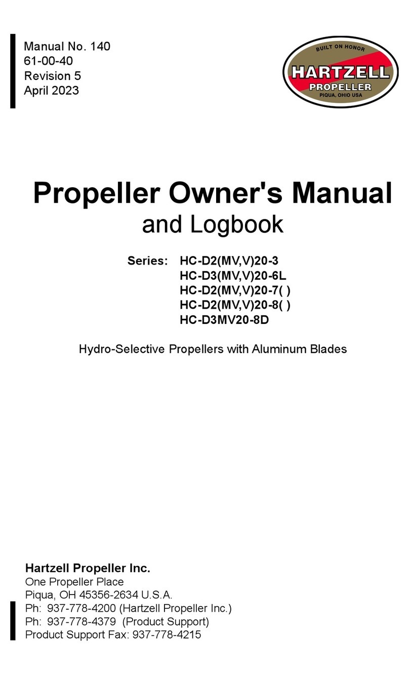
Hartzell HC-12X20 User manual

HARTZELL
Manual
No.
1000
Septem
bed5
1
inspection
Repair
Overhaul
HC-12X20
HC-D2X20
H
yd
ro-S
elect
ive
Pro
pe
I
I
e
r
Instruction
Manual
Hartzell
Propeller
Inc.
One
Propeller
Place
Piqua,
OH
45356
U.S.A.
Ph:
513-778-4200
F~X:
513-na-a~
Telex
4332032
HRlZLP
WARNING 1: THIS MANUAL IS OBSOLETE. DO NOT USE.
THIS MANUAL HAS NOT BEEN MAINTAINED BY
HARTZELL PROPELLER INC. THE FAAREQUIRES
THAT THIS DOCUMENT CONTINUE TO BE MADE
AVAILABLE.
WARNING 2: REFER TO HARTZELL PROPELLER INC. SERVICE
BULLETIN HC-SB-61-331 FOR INFORMATION
ABOUT PROPELLER MODEL UPGRADE FROM “1”
OR “8” STYLE HUBS TO “D” OR “A” STYLE HUBS.
WARNING 3: HARTZELL PROPELLER INC. COMMERCIAL
SUPPORT FOR PROPELLER MODELS
CONTAINED IN THIS MANUAL IS NOTAVAILABLE.
WARNING 4: USE OF OBSOLETE MAINTENANCE
INFORMATION OR PARTS THAT HAVE UNKNOWN
HISTORIES IS NOTAPPROVED BY HARTZELL
PROPELLER INC. AND MAY CREATE AN UNSAFE
CONDITION THAT COULD RESULT IN DEATH,
SERIOUS BODILY INJURY, AND/OR SUBSTANTIAL
PROPERTY DAMAGE.
OBSOLETE DOCUMENT – DO NOT USE
SEE COVER PAGE WARNINGS AND
SERVICE BULLETIN HC-SB-61-331

I
I1
IV
V
VI
X
N
T
E
N
MODEL
HC
-
12x20
Illustrations
inside
front
and
back
cover
Model
Designation
Description
Ins
t
a1
1
at
ion
Instructions
Operating
Instructions
Service
Instructions
Disassembly
Instructions
Assembly
Instructions
Trouble
Shooting
6
Modernization
Parts
List
MODEL
HC
-
12x20-7
and
8
Dash
7
and
8
Models
Page
26
I
Illustration
for
Section
X
-
Pages
16
and
17
Fifth Printing
(September, 1951)
OBSOLETE DOCUMENT – DO NOT USE
SEE COVER PAGE WARNINGS AND
SERVICE BULLETIN HC-SB-61-331

I
/
\
40
38
15
18
--
(PARTS
DIACRAM~
SEE
CATALOG
NUMI€#
SHEET
FOR
CARTS
IDENTIFICATION
..
OBSOLETE DOCUMENT – DO NOT USE
SEE COVER PAGE WARNINGS AND
SERVICE BULLETIN HC-SB-61-331

C
OBSOLETE DOCUMENT – DO NOT USE
SEE COVER PAGE WARNINGS AND
SERVICE BULLETIN HC-SB-61-331

I
P
SECTION
1
MODEL
DESIGNATION
A-HUE
MODEL
DESIGNATION
The
diagrammatic
description
is
self
explanatory.
A
dash
and
a
number
added
ta
the
hub
model
designation
indicates
a
minor
change
which
does
not
affect
the
eligi-
bility.
Hub
Model
Designation
HC-
12x20-1
Parts
List
S.
A.
E.
propeller
shaft
size
HC-Hartzell
Controllable
HA-Hartzell
Ad
justable
1
I
B-BLADE
MODEL
DESIGNATION
OBSOLETE DOCUMENT – DO NOT USE
SEE COVER PAGE WARNINGS AND
SERVICE BULLETIN HC-SB-61-331

SECTION
I1
DESCRIPTION
A-CONTROL
The Hartzell Hydro-Selective Propeller
is
a
hydraulic
controllable propeller.
The
pitch
of
the
blades
can
be
set
to
any
predetermined
value
within
the normal
operating
range
by
moving
the
cockpit
control
to
the
proper
position corresponding
to
the
en-
gine speed desired,
For
example,
the
push-pull
control
is
pushed
all
the
way
in
for
take-off,
and
is
pulled
out
for
high
speed
and
cruise.
An
intermediate
position
will
provide
an
intermediate pitch
setting
or
rpmvalue.
B-BLADES
The bIades are
of
a
special plastic composition
known
as
“Hartzite”.
ial
has
unusually
good
properties
for
propeHers,
such
as
high
strength,
tion
qualities,
and
is
impervious
to
the
effects
of
weather and
salt
water.
The
mater-
good
vibra-
The blades
are
made
as
thin
as
metal
blades,
consequently
the
efficiency
is
equally
high.
As
“Hartzite”
absorbs
vibrations,
it
results
in
smoother operation than
most
propeller
materials.
C-HUB
The
hub
assembly
is
unusually
simple
and
inexpensive, consisting essentially
of
a
steel
hub
element,
blade clamps
to
which
are
fastened counterweights, blade bearings
and
the
hydraulic
jack
unit.
The
hydraulic unit
consists
of
a
cylinder bolted
to
the
agine.crank
case,
a
movable pistion,
a
ball
bearing which translates
the
motion from
tbnon-rotating
piston
to the rotating
hub
assembly
by
means
of
two links,
and
the
hydraulicservo
valve.
Engine
oil
prcssure
is
used
to
acuate
the
mechanism.
--
D-MODELS
HC-12x20-I,
2,
3,
4,
5,
and
6
(See
Section
X
for
dash
7
and
8).
The
HC-12x20-1
model
has
approximately
10
to
14
degrees pitch
range,
which
is
sufficient
for
normal
low
and
high
speed
control.
The
cylinder
is
designed specifi-
cally
to mount
on
the
Continental
E185
engine,
either
directly with
studs
or indirectly
with
brackets.
The
-2
model
is
similar
to
the
-1
except
the
pitch
range
is
33
degrees
which
erables the
pitch
to
be
reversed
for
ground
or water
handling.
Also,
the
cylinder
mounts directly
to
any
engine
having
a
standard
SAE
20
spline
thrust
plate.
The
-3
model
is
the
same
as
the
-2
except
the cylinder
is
larger,
therefore
will
op-
erate
on
lower engine
oil
pressures.
(8-7/8
0.
D.
for
-3
as
compared
to
7-5/’8
0.
D.
for
-2
model.)
The-3
propeller
was
assembled
with
three
counterweightconfigurations,
as
follows:
Model
HC-12x20-3
has
counterweights
that
measure
4.65
inches
between
the ex-
treme points
of
the
long
corner
or edge.
Model
HC-12x20-3A
has
counterweights
that
measure
4.5
inches
long
and
do
not
-3-
OBSOLETE DOCUMENT – DO NOT USE
SEE COVER PAGE WARNINGS AND
SERVICE BULLETIN HC-SB-61-331

have
a
large
notch
milied
along
the
inside
corner
to
provide
clearance
for
the
Pro-
peller
hub
nut.
This model
requires
the
1/8”
increase
in
length
which
is
accomplish
ed
by
attaching
1
I
8”
or
two
1
‘16”
plates
on
the
end
of
the
counterweight using
two
10-32
cap
screws
one
inch
apart
centrally
located.
Model
HC-12x20-3C
has
counterweights
4.5
inches
long;
however, there
is
a
large
The
-4
model
is
essentially the
same
as
the
-1
model except
for
the
cylinder
mount-
ing
provision. Whereas the
-1
model
is
designed
specifically to mount
on
the
Contin-
ental
E-185
engine, either
with
brackets
or directly with
studs,
the
-4
model
utilizes
the
-2
cylinder
which
mounts
on
the
standard
S.A.E.
thrust
plate.
The
-5
model
is
an
improved version
of
the
-1.
The
litrks
which
transmit
the
MO-
notch
milled
along
the
inside
corner
to
provide
clearance
for
the
hub nut.
tion from the
hydraulic
element
to
push
rods and
forks.
The
-6
model
is
essentially
the
mounting
provision.
It
utilizes
the
thrust
plate.
When the propeller
with
grease.
The
pitch
the
blades
have
been
replaced
in
the
-5
model
by
same
as
the
-5
model
except
for
the
cylinder
-2
cylinder
which
mounts
on
the standard
SAE
SECTION
111
INSTALLATION
INSTRUCTIONS
leaves the factory
it
is
completely
assembled
and
partly
filled
of
the
blades
is
set for
its
particular application
and
&;he
clamp
and
biades
are
marked
with
matchinglines.
A-INSTALLING
PROPELLER
1.
Clean
crankshaft
and
crankcase
nose
section.
Install
bronze
rear
cone
against
the
thrust nut.
In
Ranger engine installations,
the
thrust
nut (Ranger Part
No.
7815)
must
be
removed
and
turned
down
in
a
lathe
to
3.210+.005
over
all
diameter.
2.
The
hydraulic cylinders for
model
HC-12x204,
used
on
North American built
Navions,
were
mounted
on
the
Continental
E-185 engine
with
sheet
metal
brackets.
This
was
necessitated
because
at
the
first
part
of
the
program
the engine
had
no
pto-
visions
for
bolting the cylinder directly
on
to
the
engine
crankcase.
Later
the
D
series
engines
came
through
with
four
tapped
holes
for
this
purpose.
Therefore,
two
cyIin-
der
mounting instructions
are
necessary:
a.
For
Continental engines requiring
brackets:
Locate
the
valve
near
the
top
of
the
engine,
remove
cylinder
from
propeller
assem-
bly
and
secure
it
to
the
mounting
brackets,
which
presumably
are already
bolted
to
the
engine, with Allen head
screws
making
sure
the
assembly
is
seated
fully
on
the
pilot
flange
of
the engine
crankcase.
Be
sure
that
the
brackets
pull
the
cylinder
up
tight against
the
engine
crankcase;
otherwise failures
of
the brackets
A
OBSOLETE DOCUMENT – DO NOT USE
SEE COVER PAGE WARNINGS AND
SERVICE BULLETIN HC-SB-61-331

and
propeller components
will
result.
asszmbly
back
against the crankcase,
torque
throug
h-bo1
ts.
Loosen
through-bolts
on engine
to
push
the
if
necessary.
Safely
Allen
head
screws
and
b.
Locate valve near top
of
engine
and
remove
piston
from
cylinder.
Install
a
1/64”
hayd
paper gasket between
the
cylinder
and
the
crankcase.
(It
is
also
recom-
mended that
gasket
compound
be
used.)
Use
elastic
stop
nuts
and aluminum
washers
on
the
studs inside the cylinder.
Studs
or
nuts
MUST
NOT
extend
out
more
than
5/8
inches
from
the surface
oi‘
the
cylinder,
else
the piston
will
be
pre-
vented from receeding fully.
For engines having provisions
to
bolt
th
e
cylinder directly
to
crankcase:
3.
Check the inner and outer
“0”
Rings,
also
the
“0”
ring
grooves,
of
thepiston
for
cuts
or
other
defects that
may
cause
oil
leaks,
and install
“0”
rings
and
felt
seal
on
piston.
4.
Oil
the
crackshaft,
rear
cone,
“0”
rings
and
the
inner surface
of
the
cylinder.
A
thin film of antiseize
compound
(Specification AN-C-53)
or
an
equivalent
mixture
of
70
per
cent white
Iead
and
30
per cent engine
oil
by
volume
is
advisable
on
the
threads
of
the engine
shaft.
3.
Attach
the
proper
hydraulic fittings onto the
valve
body.
6.
Place propeller
on
crankshaft
and
align
wide hub spline
with
shaft
blind
qpl’ne
(if
used).
In
the
case
of
the
-2
and
-3
models,
turn
the
nut
about two threads
he
nut.
a
rJ
the
shaft
making
sure
the
threads
have
engaged properly. Never
use
force
to
start
7.
Turn
the piston
so
the
number
stamped
on
the
flange
matches
with
the
same
!lumber
stamped
on
the
front edge
of
the
cylinder
and
so
that the
three
pins
in
the
cylinder
will
line
up
with
the
holes
in
the
piston.
8.
By
hitting
the
inboard portion
of
the
blades
with
the
palm
of
the
hands,
enter
the
piston
into the
cylinder
taking precautions
not
to
cut
the
“0”
rings in the process.
The
valve
body
should
be
at
either extreme
of
its
stroke
in
order
to
allow
air
to
escape
from
the cylinder.
piston
into
the cylinder by applying
hand
pressure
on
the
counterweights.
As
soon
as
possible
start
the
nut on th?
threads
of
the
shaft and then
push
the
9.
Tighten the
nut
on the crankshaft
using
a
bar
about
3
or
4
feet
long
with
a
10.
With
piston
bottomed in
the
cylinder,
check
travel
of
piston
by
measuring
between
jack
plate
(5)
and
shoulder
of
hub.
The
travel should
be
-413
to
375
on
models
-1
and
-5,
-507
to
,469
on
model
-4,
and
1.062
to
1.094
on
models
-2
and
-3.
Shim
behind
cone
(6)
if
distance
insufficiznt.
Safety
nut to
engine
shaft,
force
of
50
1bs.-maximum effort
of
a
man
pulling with
one
hand.
11.
Install
3/8”
to
1/2”
I.
D.
flexible
hose
from
pressure
side
of
the
engine
to
-5-
OBSOLETE DOCUMENT – DO NOT USE
SEE COVER PAGE WARNINGS AND
SERVICE BULLETIN HC-SB-61-331

the
lever side
of
the valve
and
from
the
engine
crankcase
to
valve.
This
hose
must
be
sufficiently
long
and
arranged
so
that
the
valve
can
be
moved
in
and
out freely.
Locate the drain fitting
in
the crankcase
as
close
to
the
vahe
as
possible-not
over
18
inches.
12.
With
the
cockpit
reverse control line
forward
(in
the
case
of
the reversible
propeller)
just
off
the
locked position, attach this control line
at
the propeller
to
the
short end
of
the
lever
(42)
on
the
valve
(41)
making
sure
that
the
clamping
bolt
is
tight
against the
bracket
on
the
cylinder-
When
moving
the
cockpit
reverse
control
lever
into
the
locked
position, there should,
be
an increase
in
tension
due
to
the
slack
.
being taken
up
in
the lines.
13.
With
piston
bottomed
in
the
cylinder,
the cockpit propeller
control
handle
pulled
out
approximately
2Y4”
from
the
instrument panel,
and
valve
body
located
midway
between
the cotter
pin
and
the
base
of
the guide pin;
attach
the
propeller
pitch control
line
to
the
valve
lever.
(Valve
body
shown
in
mid-position
on
parts
dia-
gram.)
14.
With
the
piston bottomed
in
the cylinder,
check
the emergency
stop
screwson
the inboard
end
of
clamps
for
clearance with
the
hub.
If
necessary, file the
head
on
screws
to
paper clearance between the
screw
and
hub.
%ADJUSTING
PROPELLER
CONTROL
FOR
PROPER
GROUND
OR
STATIC
RPM
1.
Start
and
warm
up
engine
and
check
propeller action.
The
full throttle max-
(Rpm
for
best
rate
of
climb
should
not
exceeh
imum
static
rprn,
with
cockpit propeller control fuIl
forward,
should
be
held
to
limil
listed
in
CAA
Aircraft Specification.
max
engine
speed.)
2.
If
static
rpm
is
too
high
pull
back
on
propeller
control
until correct
rprn
is
obtained.
Stop
engine
and
adjust
propeller
low
pitch
stop
screw
which
limits
the
valve
travel.
On
-1
and
-5
models
this
stop
screw
is
located
in
a
bracket
carried
by
the
valve
lever.
The
end
of
the
screw
bumps
against
the
back
of
the
cylinder
when
the
propeller
is
pulled
into
low
pitch.
For
the
-2
and
-3
models
this
screw
is
held
by
a
bracket
that
is
bolted
to
the cylinder. It
is
adjusted
to
limit
the
movement
of
the
Val-
ve
lever.
For
the
-4
and
-6
models
the
screw
adjusts
directly
against
the
valve
body.
,
3.
If
static
rpm
is
too
low,
stop engine and
back
off
enough
on
low
pitch
stop
screw
and
run
up
engine
again
as
in
paragraph
2.
4.
If
the correct
rprn
cannot
be
reached
because
the
jack plate
is
against the
shoulder
on
the
hub,
reset the
blade
pitch
about
one
degree,
or
1/32
inch
measured
at
the
scribe
marks,
for
each
100
rprn
desired.
The propeller
should
never operate with
the
jack
plate against
the
shoulder
be-
cause
the
cylinder
oil
pressure
is
then
equal
to
the engine
oil
pressure.
This
pressure.
which
may
be
considerably higher than
normal
cylinder
operating pressure,
loads up
both
the
propeller
thrust bearing and
the
engine thrust bearing
needlessly.
The
minimum
clearance
should
be
about
,010”.
-6-
OBSOLETE DOCUMENT – DO NOT USE
SEE COVER PAGE WARNINGS AND
SERVICE BULLETIN HC-SB-61-331

5.
After run-up
fill
propeller blade
bearings
with
grease
recommended in Parts
,ist
using
zerk
fittings
on
clamps.
Stop
when grease appears between
clamp
and
hub.
Care must be
taken
that
the
pressure
does
not
blow
out gaskets
in
clamps.
6.
Checir
pitch
control
in
flight
for
proper
operating
range.
SECTION
IV
PILOT
OPERATING
INSTRUCTIONS
A-HIGH-LOW
PITCH
The
Hartzell-Hydro-Selective
Propeller
operates
with engine
oil
pressure
to
reduce
pitch,
and
centrifugal
force
created
by
the
counterweights to
increase
pitch.
A
servo
valve
regulates
the
oil
flow
to
provide
any
desired
pitch setting within limits
of
pitch
range.
The pilot regulates the
valve
with
a
push
pull control
in
the
same
manner
that
he
regulates
the
throttle.
He
pushes
the
control
IN
to
INCREASE
RPM
and
pulls
it
OUT
to
DECREASE
RPM.
The
blade
follows
the
control
precisely,
the
rpm
will
re-
flect this movement immediately.
a.
WARM-UP
During warm-up
the
pitch
control
should
be
IN
or
in
low
pitch.
Then
set
rpm
at
1500
with
the throttle and check
pitch
change
once
or
twice.
This
will
also
fill
cylinder
with
warm
oil.
b.
TAKE-OFF
No
pitch control
is
necessary.
The
rpm
should
increase
to
nearly the desired
climbing value
by
the
time
the
airplane
leaves
the
ground
without
changing
the
pitch
control.
c.
CLIMB
If
rpm
exceeds
the limit allowed it
may
be
decreased
by
pulling
back
on
the
pitch
control until
the
desired value
is
reached.
d.
CRUISE
Pull
pitch control
out
to
cruise
position.
If
manifold
pressure
gauge
is
available
the
rpm
and
manifold
pressure
can
be
correlated
with
pitch
control
and
throttle
as
recommended
by
engine
manufacturer
for best
fuel consumption
or
best
en-
gine
performance.
e.
LONG
RANGE
CRUISE
Maximum
cruise
econcrny
dictates
low
airspeed,
low
rpm
and
fairly high
man&
fold
pressure.
For
these
conditions
the
pitch
must
be
high.
This
can
be
obtained
-7-
OBSOLETE DOCUMENT – DO NOT USE
SEE COVER PAGE WARNINGS AND
SERVICE BULLETIN HC-SB-61-331

.
with
pitch
control pulled
OUT
to
desired
value
of
rpm
and
manifold pressure.
f.
LANDING
Push
control
in
before landing
in
order
to
be
in
a
position to take-off again
if
nee-
essary.
Taxi
in
low pitch.
B-REVERSE
PITCH
Model
HC-12x20-2
and
-3,
reversible
propellers,
go
into reverse
pitch
with engine
oil
pressure
and
comes out
of
reverse
by
centrifugai
force
created
by
the
counter-
weights.
Before
attempting
to
reverse the
pitch
the
rprn
must
be
reduced
to
1200
or
less
for engines having oil pressure less
than
50
lbs.
Generally, the
lower
rpm
the
less
is
the time
for
the’
pitch
to go completely
into
reverse, depending on the oil pressure
available at idling speeds.
For
the
Sea-bee
installation, unscrew and
push
up
the reversing control and slowly
push
towards the
rear.
DO
NOT
FORCE.
The Dilot
can
feel
the
control yield
to
his
pressure ineicating
that
the
pitch
is
changing. When
the
control
is
all
the way
back
the pitch is
in
reverse
and
the pilot
can
then apply
throttle.
UNDER
NO
CONDI-
TIONS
SHOULD
ONE
OPEN
THE
THROT“LE
WHILE
THE
REVERSE
CONTROL
IS
IN
AN
INTERMEDIATE
POSITION.
If
there
is
any
doubt whether the
pitch
is
corn-
pletely in reverse
open
the
throttle
slow~y
to
avoid
the
possibility
of
the
engine racing.
Never let
the
engine exceed
2500
in
reverse
in
the
case
of
Franklin Engine
6AL500.
In
order
to
come
out
of
reverse
the
rpm
should be
set
AT
LEAST
1200.
The high
er
the
rpm
without exceeding the limitation
of
apDroximateiy
2500,
the
fasterthe
pitch
changes
out
of
reverse.
Apply
forward
pressure to
the
reverse
conlrol
until
it
slips
into the lock position.
LOCK.
Any
monetary rpm increase up
to
the limitation
of
the engine is
not
to
be
a
Cause of concern
as
some
speed
up
is
inevitable
when
the
pitch
goes
through zero.
C-PROPELLER
CARE
It
is
advisable
to
turn the
propeller
into
a
horizontal position
on
preparing the
ship
for
tie-down
or
hangering.
In
this
position
it
will
not
permit
water
to
drain
be-
tween
the
clamp
and
hub
into the blade
bearing,
and
in
this position
the
propeller
can-
not
be
damaged
by
hitting the overhead portion
of
the
hanger.
Since
the
blades
are
solid
“Hartzite” through and
through
with
good
weathering
characteristics,
covers
for
them
are
not
a
necessity.
It
is
advisable,
however, to
cover
the
hub
and
hydraulic elements
with
a
waterproof
hood
when
storing
in
the
open.
In
cleaning
the
propeller,
use
grease-cutting
soap
and
water
to
wash
the
blades and car-
bon
tetrachloride
or
naptha
to
clean
the
hub.
Most
automobile waxes
used
on
th2
blades will
give
them
lustre and
protection.
A
waxed surface
is
also
of
some
advantage
aer
od
ynarnicall
y.
In
order to minimize water
erosion
in the
case
of
the
“Sea-bee”,
all
water
taxy-
ing
should
be
done
in
low
pitch
and
with
wing
flaps down.
The
pilot
should
perform the
daily
visual inspection
its
listed
in
Section
V,
Part
A.
4-
OBSOLETE DOCUMENT – DO NOT USE
SEE COVER PAGE WARNINGS AND
SERVICE BULLETIN HC-SB-61-331

SECTION
V
SERVICE
INSTRUCTIONS
A-DAILY
VISUAL
INSPECTION
The
propeller
should
be
regularly
and
carefully
inspected
visually
for
the
follow-
ing:
1.
Excessive
oil
leaks
in
the
hydraulic element
and
valve.
Replace
“0”
rings
when
necessary.
A
true
source
of
leaks
can
best
be
discovered
by
standing
off
to
a
side
clear
of
the
propeller and watching
the
valve
and
cylinder,
or
by
wiping
all
visible
oil
from
the engine, propeller and cowling
and
then starting
the
engine
for
a
very
short
period
of
time.
2.
Grease
leaks
through
the
clamp
gaskets.
Replace
gaskets
if
necessary
its
de-
scribed
in
Section
VII,
Part
D.
Use
non-hardening
gasket
compound.
3.
Cracks
in
the hub
or
clamps,
and
particularly
the
links
in
linkplate
(5).
Never
hesitate
performing
a
magnetic
check
at
the
first
sign
of
a
crack.
4.
Bruises,
dents
ur
cracks
in the
blades.
See
CAA
Manual
18
for
the
allowable
damage
to
be
airworthy.
(Major
repairs should
be
made
only
by
a certified agency
or
the
factory.)
The
metal
leading
edge
is
stainless
steel
and
is
expected
to
crack
around
the
leading
edge
only
along
the
scribed
lines
put
in
the
metal
for
this
purpose.
Missing
metal
or
hose
rivets
should
be
repaired. See Section
VTII
Part
E
instruc-
311s
for
replacing
rivets.
HAVE
THE
TIPPING
REPAIRED
WHEN
SMALL
PITS
AP-
EAR
ON
THE
TIPS.
This
is
especially
true
on
the propellers
used
on
amphibians.
If
the
water
penetrates
the
stainless steel
tipping,
the
plastic
beneath
it
can
be
dam-
aged beyond repair in
a
very
short
period
of
time
if
the
punishment
is
severe.
Armor
tipping
should
be
refiled
to
a
sharp
edge
at
the first
sign
of
pits
on
the
leading
edge.
5.
Check
the
scribed
lines
on
the
clamps
and
blades
to
see
if
they
are
matching.
The
reason
for
this
precaution
is
to
detect
blades
that
may
slowly be twisting
to
flat
pitch
because
the
clamps
are
not
tight
enough
on
the
shanks
of
the blades.
These
matching
lines
must
be
present originately
and
can
be
scribed
in
with
a
scale
and
scriber. See Section
VIII,
Part
F.
Check blades
for
free
movement
in
the
hub.
Grab
counterweights
and
move
both forward
and
then
backward making
sure
at
the
time
that
the
valve
is
against
the
cotter
pin
of the
guide
pin.
In
this
position,
oil
can
bleed
out
of
the cylinder.
6.
#
7.
Check
pitch
control
connections
to
valve
lever.
This
is
especially
true
in
the
case
of
the
reverse
control
connection
on
the
HC-12x204
and
-3
propellers.
The
head
of
the
bolt
attaching
this
control line
to
the
valve
lever
should
be
hard
against
thestop
bracket
on
the
cylinder.
Check
by
pulling
on
the
valve
body.
See
Section
III
Part
A-12
for
attaching
this
control
to
the
lever.
E!-50
HOUR
INSPECTION
1.
Follow
the
regular
inspection procedures
as
listed
under
Part
A.
-a
OBSOLETE DOCUMENT – DO NOT USE
SEE COVER PAGE WARNINGS AND
SERVICE BULLETIN HC-SB-61-331

?
b
2,
Check
wear
in
valve
lever
linkage.
Replace
pins
or
lever
if
excessively
worn
The
valve
lever
is
extremely
sensative,
and
for
correct
operation
the
valve should
re-
spond
immediately
with
the
movements
of
the
cockpit
control.
Replace
worn
parts
if
pitch
control
is
not
precise,
1.
2.
3.
4.
3.
Grease
the
thrust
bearing
located
in
the
hydraulic
element
by
any
of
th-
*
three
methods.
Too
much
grease
will
cause
it
to
overheat.
Use
only
the
recommended
greases
listed
in
Section
IX.
a.
Take
the
screws
out
of
the
cover
plate
on
the
piston
and
drop
about
two
tea-
spoonful
of
grease
between
the
cover plate
and
piston.
b,
If
a
zerk
fitting
is
in
the
piston,
pump
about one-half cubic
inch
of
grease
into
the
bearing.
c.
Remove the propeller
from
the
engine
as
a
unit
including
the
piston.
Work
grease
in
the
1/16
crack
between
the
I.
D.
of
bearing
using
ones
fingers.
4.
Grease blade bearing
with
zerk
gun.
Care
should
be
exercised
whin
pumping
grease into
the
zerk
fitting,
else
excessive
pressure
will
blow
out
the
gaskets.
Grease
should
be
added
until
it
starts
corning
out
around
joint
between
the
clamp
and
hub.
Unless
the
bearings
are
kept
flooded
with
grease
they
will
become
rough
and
eventual-
ly
cause
the
propeller
to
stick.
See
list
of
recommended
greases
in
Section
IX.
5.
Check
tightness
of
linkscrew
(25)
and
also
wear
between
screw
and
link
of
(5).
Linkscrew
(25)
must
be
tight
in
clamp
(24)
else
it
will
work
and
possibly
break.
Torque
to
approximately
30
foot
pounds.
Safety
with
wirelock
(28)
in
such
a
way
tkt
wire
tends
to
tighten
screw.
Replace
screw
if
badly
worn.
6.
Check
clamp
gaskets
for
leakage
of
grease.
For
remedy
see
Section
VI1
Part
D.
C-250
HOUR
INSPECTION
(or
coincide
with
engine
overhaul).
Remove
propeller
and
disassemble.
Magniflux
steel
parts.
Replace
worn
parts.
Assemble.
SECTION
VI
DISASSEMBLY
r~sTRtJcmoNs
The
parts
will
be
referred
to
by
name
and
number
as
listed
in
the
Parts
List
Set-
tion
IX
which
refers
to
the
exploded
view
and
general
drawing
shown
on
the
cover.
A-REMOVAL
OF
HUB
AND
BLADE
ASSEMBLY
FROM
ENGINE
a.
Without
piston
and
cylinder.
1.
Remove wirelocks
(28)
and
linkscrews
(25).
2.
Replace
linkscrews
in
the
Same
Clamps
from
which
they
were
removed.
3.
Remove
safety
screw
(16)
in
nut
(
15)
and
turn
nut
off
of
enpne
shaft.
-10-
OBSOLETE DOCUMENT – DO NOT USE
SEE COVER PAGE WARNINGS AND
SERVICE BULLETIN HC-SB-61-331

4.
Remove
hub
from
engine
shaft
and
place
away
from
possible damage.
b.
With
piston
and
cylinder
1.
Remove
cotter
pin
(38)
from
valve
guide
on
valve
bracket
a
(40).
2.
Grab
counterweights
and
pull
piston
as
far
out
of
cylinder
as
possible.
Valve
3.
Rehove
safety
screw
(16)
in
nut
(15)
and
turn
nut
off
engine
shdft.
4.
Repeat
instruction
2
above
until
piston
is
entirely
out
of
cylinder.
Provide
a
5.
Remove
hub
from
engine
shaft
and
place
on
stub
shaft
of
a
work
bench.
6.
Remove
cylinder
and
valve
parts from
engine.
must
be
in
high
pitch
position
in
order
to
bleed
air
into cylinder.
pan
to
catch
the
oil
draining
from
cylinder.
F-REMO’;JAL
OF
PROPELLER
BLADES.
1.
2.
3.
Take
nuts
(13)
off
of
bolts
(12)
and
remove
Mlen
screws
(14)
using
Allen
wrench
(5
16”
across
the
flats).
4.
Record
blade
serial
number
with
the
clamp
number
for
each
side
of
the
pro-
peller.
5.
Remove
clamp
halves
(8)
and
(24)
from
assembly,
The
blade
is
then
free
to
Remove
piston
from propeller
assembly
replacing
the
linkscrews
i
n
t
h
e
Scribe
matching
lines
on
bladesand
clamps.
clamps
from which
they
were
removed.
pulled
off
of
pilot
tube
in
hub.
C-REMOVAL
OF
BLADE
BEARING
1.
Pull
“0”
ring
(26)
out
of
the
groove
in
hub
and
roll
it
back
on
the
hub.
2.
Spring
snap
ring
(27)
and
move
back
into
the
“0”
ring
groove.
NOTE:
Hold
the’bearing
together
or
use
two
small
C
clamps,
for
this
operation
will
permit
the
two
races
of
the
bearings
to
part
allowing
the
balls
to
come
out.
3.
Tap
the
bearing
(22)
back
toward
the
snap
ring
and
off
of
split ring
(23).
4.
Remove
split
ring
and the
bearing,
snap
ring
and
“Q”
ring
will
then
be
free
to
come
off
the
hub:
D-REMOVAL
OF
JACK
ASSEMBLY
FROM
PISTON
ASSEMBLY
Back
wire
retainer
(34)
out
of
slot
using
plyers.
A
sharp
1/16’’
dia.
piano
wire
bent
90
degrees
will
aid
in
prying
the
wire
retainer
(34)
out
to
where
it
can
be
reached
with
plyers.
Push
or
tap
the
jack
plate
out
of
the
bearing
using
preferably
a
cylinder
of
steel
whose
0.
D.
is
slightly
less the
I.
D.
of
the
bearing.
1.
1
2.
ELREMOVAL
OF
BEARING
FROM
PISTON
1.
Remove
screws
(35)
holding
on
cover
plate
(4).
-1
1-
OBSOLETE DOCUMENT – DO NOT USE
SEE COVER PAGE WARNINGS AND
SERVICE BULLETIN HC-SB-61-331

a
I
2.
Push
or
tap
bearing
(3)
out
of
piston
(2).
Support
the
piston
on
the
front
nm.
Us?
a
drift
punch
applied
to
the
inner
edge
of
the
bearing.
F-DO
NOT
remove
counterweights
from
damps
as
they
are
pinned
at
the
factory
and
should
not
be
loosened.
DO
NOT
remove
links
from
jack
assembly
(5).
If
links
should
be
replaced
return
assembly
to
factory.
DO
NOT
interchange
cylinders
and
pistons
for
they
are
paired
by
stamped
num-
bers
on
the
outer
edges
of
both.
DO
NOT
interchange
the
valve
body
and
valve plate
on
the
“C”
series
valve
assem-
blies.
SECTION
vrI
ASSEMBLY
INSTRUCTIONS
The
parts
will
be
referred
to
by
name
and
number
as
listed
in
the
Parts
List
Sec-
tion
IX
which
refers
to
the
exploded
view
and
general
drawing
shown
an
the
cover.
A-INSTALLATiON
OF
JACK
IN
BEARING
1.
Push
or
tap
jack plate
(5)
in
bearing
(3)
with
the cover
plate
(4)
and
gasket
(32)
between
the
two.
The
groove
just
inside
the
inner
race
of
the
bearing
must
match
the
groove
in
the
jack
plate.
2.
Install
wire
retainer
(34)
through
slot
in
jack
plate.
(5).
Use
plyers
to
work
wire
around
groove,
B-INSTALLATION
OF
BEARING
IN
PISTON
1.
Grease bearing
(3)
with
1/2
cubic
inch
of
grease.
(See
greases
recommended
2.
Press
bearing
(3)
in
piston
(2).
Slight
press
fit
is
required.
Use
gasket
3.
Use
gasket
compound
on
gasket
(32).
4.
Insert
lock
washers
(33)
and
screws
(35)
in
cover
plate
(4)
and
piston
(2)
*
listed
in
Section
IX).
compound
between
bearing
and
piston
to
insure
tight
fit
if
necessary.
C-INSTALLATION
OF
BLADE
BEARING
1.
Install
“0”
ring
(26)
over
tube
in
hub
(7)
past
the
“0”
ring
groove.
2.
Install
snap
ring
(27)
in
“0”
ring
groove.
3.
Install
bearing
(22)
over
tube
with
the
NARROW
RACE
PLACED
ON
FIRST.
4.
Move
bearing
against
snap
ring
and
install
like
numbered
split
ring
(23)
just
5.
Tap
bearing
over
split
ring
until
against
shoulder.
6.
Slip
snap
ring
from
“O”
ring
groove
and
place
between
bearing
and
shoulder
of
hub,
back
of
the
thrust
shoulder
on
hub.
-12-
OBSOLETE DOCUMENT – DO NOT USE
SEE COVER PAGE WARNINGS AND
SERVICE BULLETIN HC-SB-61-331

7.
Roll
"0"
ring
into
groove.
Engine
Installation
-1
i
-2
.
-3
-4
D-INSTALLATION
OF
PROPELLER
BLADES
-5
1.
Fill
propeller
blade
shank
pilot
tube
hoIe
with
grease,
conforming
to
Grease
Specifications
listed
in
Parts
List.
Be
sure
air
is
not
trapped
below
grease
as
this
will
affect
balance
of
propeller.
(For
-2
and
-3
propellers
instail
staking lug
over
heads
of
two
screws
at
base
of
blade.
Lug
must
match
up
with
hole
in
clamp
when
pitch
is
set
properly),
2.
Place
propeller
blade
on
tube
of
hub-
-
Continental
E-I85
120
Ranger
6-440C
-
2
*
200
6-44OC-5
*
180
Franklin
6AL500
3.
4.
Put
hardening
gasket
compound
around
the
blade shank
in
the
inboard
Install
MATCHING
pair
of
clamps
(8)
and
(24).
groove.
120
10"
*
180
5.
Place
gaskets
(10)
in
place
with
nm-hardening
gasket
compound
on
both
sides
of
gaskets.
6.
with
valve.
7.
Insert
screws
(14)
and
bolts
(12)
in
the
same
direction
to
avoid
inlerference
Tighten
screws
(14)
and
nuts
(13)
evenly,
torque
approximately
20
foot
Ibs.
8.
Check
freedom
of
blades
on
pilot
tube
uf
hub.
If
tight,
correct cause of
tightness
by
loosening
outer
nuts
slightly.
If
this
is
sufficient
without
permitting
the
dace
io
turn
in
the
clamps,
then
refer
to
the
causes
of
friction
listed
in
Section
VIII,
Part
A.
9.
Install jackplate
(5)
on
the
propeler
assembly
using
link
screws
(25).
10.
With
the
jackplate
against
the
shoulder
on
the
hub,
set
the
angles
of the
blades
at
the
30-in.
station
by
loosening
clamps
and
rotating
blades
in
clamps.
Set
pitch
as
indicated
in
table
below.
*
Note:
A 1-1/16
to
1-3/32
spacer must
be
used
between
jack
plate
and
hub.
11.
Scribe matching
lines
on
the blades
and
clamp.
12.
Tighten
the
nuts
(13)
until
snug
or
not
over
20
foot
lb.
torque.
Check
tight-
ness
of
blades
in
clamp
in
the
case
of
-I,
4
-5
and
-6
models.
A
torque
of
2000
inch
Ib.
should
be
applied
to
the
blade
near
the
root
to
determine
whether
it
might slip
in
ilight.
If
the
blades
slip
in
metal
to
metal
clamp,
remove
the
clamps
and
file
the
two
pads
on
the
ears
of
the
one
clamphalf.
Remove
only
.005
at a
time.
-13-
OBSOLETE DOCUMENT – DO NOT USE
SEE COVER PAGE WARNINGS AND
SERVICE BULLETIN HC-SB-61-331

13.
Carefully
check
the
angles
making
sure
the jackplate
is
against
the
shoulder
on
the
hub or
against
spacer
as
noted
€or
-2
and
-3
models.
The
angles
of
the
blades
should
be
within
$$
degree
of
each
other
and
L/2
degree
of
the
correct
angle
setting.
14.
For
-2
and
-3
propellers
drill staking
lug
through
hole
in clamp
using
,154
dia.
drill.
Hole
should
be
only
5/16
deep.
Drive
staking
pin
in
hole
flush
with
surface
of
clamp.
Staking
pin
is
necessary
to
prevent
blade
from
turning
in
clamp.
E-BALANCE
1.
Remove
hydraulic
element
from
blade
hub
assembly.
2.
Install
balancing jackplate
assembly
(These
may
be
obtained
from
factory).
Jackplate
shouId
rest
against
hub
shoulder.
Wedge
blades
out,
using
small
wedges
be-
twem
hub and
clamps.
3.
Install
balancing
mandrel using
the
cone
seats
for
centering.
Do
not
use
the
I.
D.
of
the
hub.
4,
Check
horizontal balance
by
laying
weight
slugs
(47)
in
the
corner
of
the
blade
and
clamp.
Record
no.
of
slugs
on
clamp.
5.
Apply
it
vertical
force
of
about
50-100
lb.
near
tip of
each blade
and
check
vertical
balance
having
the
heavy
blade
up.
Lay
slugs
on
the
hub
end
of
the
clamp.
Record
no.
of
slugs
on
the
side
of
hub.
6.
Repeat
item
5
above with propeller
rotated
180
degrees
and
check
vzrtical
bal-
ance
having
the
heavy blade
up
and
record
slugs.
7.
If
the
two
recorded number
of
slugs
for
vertical balance have
occurred
on
the
same
side
of
the
hub,
correct
amount
of
slugs
to
use
is
one
half
of
the
sum.
If
the
two
recorded
number
of
slugs
€or
vertical
balance
have
occured
on
opposite
s:des
of
the
hub,
the
correct
amount
of
slugs
td
use
is
one-half
of
the
difference
and
placed
on
the
side
with
the
greater
number.
Divide
the
vertical
balance
slugs
to
maintain
the
horizontal balance
within
one
slug.
Vertical
balance
should
be
held
within
four
slugs
at
the
worst
condition.
Do
not
attach
more
than
eight
slugs
on
two
fillister
head
screws.
8.
9.
10.
11.
Safety
filIister
head
screws.
Install
slugs
on
clamps
temporarily
and
again
check
balance.
Grease
blades
with
zerk
gun
equaiIy
on
both
sides.
See
Section
V
Part
B-4.
Check
horizontal
and
vertical
balance.
Add
grease
until
in
balance.
F-INSTALLATION
OF
LINKSCREWS
1.
Attach
hydraulic
element
with
linkscrews.
2.
Tighten
linkscrews
with
allen
wrench
using
30
ft.
lbs.
torque.
The
tapered
shoulder
on
the
screw
must
be
seated
on
the
tapered
countersink
in
the
clamp.
3.
If
the
hole
in
the
head
of
the
linkscrew
does
not
line
up
so
that
when
the
wirelock
is
in
place,
the
spring
or
stress
should
tend to
ti.ghten
the
linkscrew;
then
center
punch
the
proper
location
and
drill
a
hole
with
a
No.
41
drill.
-1A
OBSOLETE DOCUMENT – DO NOT USE
SEE COVER PAGE WARNINGS AND
SERVICE BULLETIN HC-SB-61-331

SECTION
VI11
TROUBLE
SHOOTING
AND
RECENT
IMPROVEMENTS
Following
is
a
list
of
the
possible
ailments
and
the
remedy.
A-FAILURE
FOR
PITCH
TO
CHANGE
1.
If
the
pitch
changes to
high
pitch
but
will
not change to
low
pitch
properly,
the
cause
is
generally
low
engine oil
pressure.
For
proper
functioning
with
a
’7%
inch
diameter
cylinder
the
pressure
should
not
be
below
45
psi.
and
with
an
8-7/8
in.
dia. cylinder, not
below
30
psi.
If
it
is
no
I
pressure,
refer
to
the
causes
of
friction
as
listed below.
2.
If
the
pitch
changes
to
low
pitch
but
will
not
change to
high
pitch properly,
the
cause
is
usually
a
drain line
that
is
either
too
small
or
too long. The
drainJim
should
never
be less
than
a
3/8”
line,
and
if
possible
it
should
return directly
to
the
crankcase
through
a
distance
of
not
over
18
inches.
Also
refer
to
the
causes
of
fric-
tion
as
listed
below.
3.’
If
the pitch
does
not
change
properly toward both
high
and
low pitch,
the
cause
is
usually due
to
an
excessive
amoun,
of
friction
which
minimizes
the
hydraulic
and
counterweight
forces
or
a
combinatim
of
low
oil
pressure
and
a
drain
line
that
is
too
small
or
too
long.
The
causes
of
friction
are:
a.
Improper grease
which,
due
to
centrifugal
force
or the presence
of
a
small
amount
of
water,
solidifies
and
causes
a
tight
fit
of
the
blade
on
the
pilot tube.
Use recommended
greases
aa
listed
in
Section
XX.
b.
The
snap
ring
(27)
wedged
beneath
the
inboard
race
of
the blade
bearing.
This
condition
can
be
detected
by
carefully
removing
one
of
the
clamp
halves
and
noting
the
position
of
the
ring.
By
removing
this
snap
ring
as
described
Section
VI,
Part
C,
and
springing
it
apart
slightly,
the
ring
will
not
jam
between
the
bearing
and
hub.
c.
of
this
section
for
the
amount
of
clearance
necessary.
Insufficient-clearance
between
the
blade
bore
and
the
pilot
tube.
See
Part
1
d.
Over
squeezing
of
the
blade
by
the
clamps:
For
early
clamps
that
do
not have
metal
to metal contacting
surfaces
on
each
corner,
it
is
possible
to
tighten
bolts
(12)
to
the
point where
the
blade
is
deformed
and
tightens
upon
the
pilot
tube.
This
overtightness
can
be
detected
by
backing
off
the castellated nuts
(13).
If
this
frees
the
rotation
of
the blades
on
the
tube
of
the
hub,
then
disassemble
and
assemble
the
blades
as
described
in
Section
VI,
Part
B,
and Section
VII,
Part
D,
ushg
new
clamp
gaskets.
If
the
blade
has
taken
a
permanent
set,
it
should
be
reamed
with
a
clamp
installed
and
properly
tightened.
The
hole
size
should
be
1.502
-
1.504
with
the
clamp
mounted
on
blade
alone
and
properly
tightened.
e.
Pilot
tubes
that
slip
out
of
the
hub
due
to
vibration
and
centrifugal
force:
-15-
OBSOLETE DOCUMENT – DO NOT USE
SEE COVER PAGE WARNINGS AND
SERVICE BULLETIN HC-SB-61-331

OBSOLETE DOCUMENT – DO NOT USE
SEE COVER PAGE WARNINGS AND
SERVICE BULLETIN HC-SB-61-331

.
Some
tubes which
had
improper
press
fits,might
work
loose
and
slide
outwal-d
ly
until
they
press
hard against
the
bottom
of
.the hole
in
the
blade
shank.
This
condition
can
be
detected
by
removing
the
wirelock and linkscrew
and
then
backing off the castellated nuts
on
the
clamp.
If
the blade does not rotate
freely
even upon
removing
the nuts
from
the bolts, the indications point to
the
condi-
tion
of
a
loose tube.
In
order to
check
further, remove the
blade
as
outlined
in
Section
VI,
Part
B,
and
measure the length
of
the pilot
tube
extending
beyond
the
hub.
This
dimension should
be
3
3/4”+1/32”.
If
the tube
has
slipped slightly, it
should
be
replaced
by
one
which
is
.002
greater
in diameter
for
the portion which
fits
into the hub.
Tube
pullers are available
for
service establishments
as
are oversize tubes.
New
tubes
may
be
pressed in
using
an
arbor
press. (In emergencies where
no
press
is
available the tube
may
be
driven
in
with
a
wooden
mall.)
Check
replaced tubes
for
fit
by
attempting
to
pull
it
with
a
puller
by
putting
a
torque
of
30
ft.
lbs.
on
the tube-puller screw,
having the threads well greased, or
by
applying
the maximum force
of
one
man
with
his
hands ten inches apart.
If
the tube
does
not
slip
in
the
hub it
is
suffic-
iently tight.
If
the tube
slips,
install
one
of
greater oversize.
f.
Insufficient clearance between the end
of
the hub and the
end
of
the blade:
This
can
be
checked
by
moving the blade by hand in and out, radially. There
should be
a
slight
end
movement.
If
there
is
no clearance, the end
of
the
blades
should
be
scraped
a
few
thousands
of
an inch at
a
time until clearance
is
produc-
ed.
Clearances should be at least
.005.
B-IMPROPER
RPM
SETTINGS
1.
Static
rpm
too
low:
The
limits
for
full throttle maximum static
rpm
are
listed
in the
CAA
Aircraft
Specification. (It
is
the
rpm
that
will
permit the rated engine speed during the
best
rate
of
climb.) Adjust
stop
that controls
the
valve
lever
travel
so
that the
proper
rpm
is
obtained. The correct procedure
is
given in Section
111,
Part
B.
If
the
valve lever
stop
is
not controlling the
travel
of
the
push
pull
control
because
it
is
limited
in
the
cockpit,
then loosen the
control
housing
clamp next
to
the valve
and move the control housing toward
the
propeller until the stop
on
the
lever limits
the lever movement.
Then
adjust
stop
to give
proper
static rpm.
If
the piston travel
is
limited
by
the
hub
low pitch
stop
(when
jack plate touches
hub)
then
the pitch
of
the blades must
be
reduced. See Section
111,
Part
84.
2.
Static rpm
too
high:
This
condition can readily
be
corrected
by
running
the
engine
at
full thxottle
and pulling back on the cockpit propeller control until the correct static rpm
is
ob-
tained.
Then
stop engine
and
adjust propdler
low
pitch stop
screw
until
it
bears
against
the controlling
surface.
3.
Cruise rpm
too
high with respect to manifold pressure:
The
high pitch
posi-
tion
is
not
correct
and
is
due
to:
a.
Improper
travel
of
the piston
in
reIation to the hub.
This
stroke
can
be
b,
-18-
OBSOLETE DOCUMENT – DO NOT USE
SEE COVER PAGE WARNINGS AND
SERVICE BULLETIN HC-SB-61-331
This manual suits for next models
2
Table of contents
Other Hartzell Aircraft manuals
Hartzell
Hartzell HC-B3-2 Series User manual

Hartzell
Hartzell HC-D2MV20-3 Series User manual

Hartzell
Hartzell HC-E3YR-7 User manual

Hartzell
Hartzell HC-Y-1 Series User manual

Hartzell
Hartzell HC-E4 3 Series User manual
Hartzell
Hartzell HC-A6A-3 Series User manual

Hartzell
Hartzell HC-82XF-1 User manual
Hartzell
Hartzell HC-D2X20-3 User manual

Hartzell
Hartzell HC-D2MV20-3 Series User manual