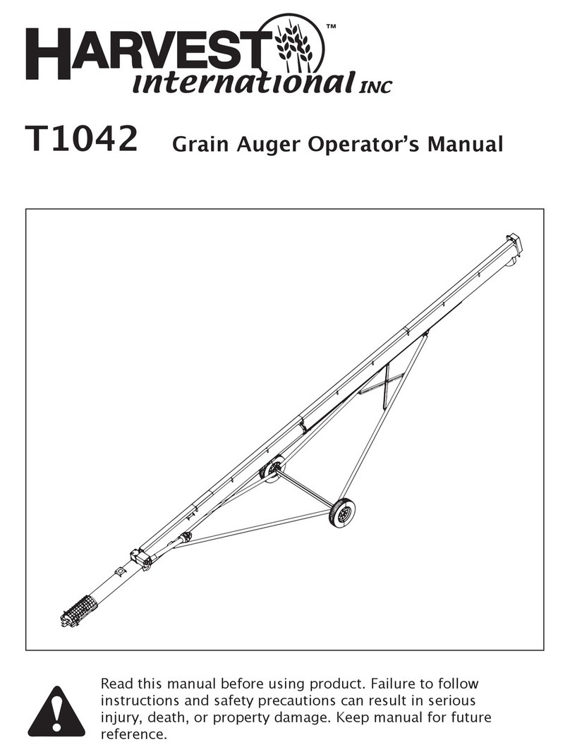
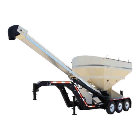
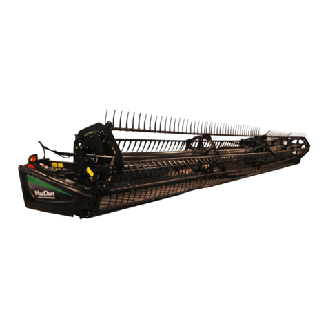
HARVEST H13112 User manual

H13112
ASSEMBLY MANUAL
(Do not operate with guards missing!)
(Do not operate tractor PTO over 540 RPM)
Read & understand all instructions pertaining to this option prior to operate.

Page 2of 68
Contents
H13112 Assemble Manual ...................................................................................................................................................... 8
Tools Needed To Assembly ..................................................................................................................................................... 9
Receiving and Unpacking .................................................................................................................................................. 10
Missing, Damaged or Replacement Parts ......................................................................................................................... 10
Where to Start .................................................................................................................................................................. 10
AUGER TUBE IDENTIFICATION .......................................................................................................................................... 11
Flighting and Tube Assembly ............................................................................................................................................ 12
Step 2...............................................................................................................................................................13
Step 3...............................................................................................................................................................13
Step 4...............................................................................................................................................................14
Discharge Assembly Installation ....................................................................................................................................... 14
Step 5...............................................................................................................................................................14
Step 7...............................................................................................................................................................15
Step 8...............................................................................................................................................................16
Step 9...............................................................................................................................................................16
You’re ready to install the In-Feed Housing...................................................................................................................... 17
Step 10.............................................................................................................................................................17
Step 11.............................................................................................................................................................17
Step 12.............................................................................................................................................................18
Step 13.............................................................................................................................................................19
Step 14.............................................................................................................................................................20
Step 15.............................................................................................................................................................21
Drive line (PTO) installation .............................................................................................................................................. 22
Step 16.............................................................................................................................................................22
Jack Stand installation....................................................................................................................................................... 25
Step 17.............................................................................................................................................................25
Installation of clean out and cover plates......................................................................................................................... 25
Step 18.............................................................................................................................................................25
Swing hopper lift arm........................................................................................................................................................ 27
........................................................................................................................................................................27
Step 19.............................................................................................................................................................27
Installing the hydraulic lines and valves............................................................................................................................ 28
Step 20.............................................................................................................................................................28

Page 3of 68
Installation of cable brackets ............................................................................................................................................ 29
STEP 21 ............................................................................................................................................................29
Installation of backbone (option)...................................................................................................................................... 31
Step 22.............................................................................................................................................................31
Installation of the cables................................................................................................................................................... 31
Step 23.............................................................................................................................................................31
You are now ready to assemble the Under Carriage........................................................................................................ 35
Step 24.............................................................................................................................................................35
Installation of manual holder............................................................................................................................................ 44
Step 25.............................................................................................................................................................44
Installation of winch bracket............................................................................................................................................. 45
Step 26.............................................................................................................................................................45
Winch assembly ................................................................................................................................................................ 47
Step 27.............................................................................................................................................................47
Swing tube and hopper assembly ..................................................................................................................................... 47
Step 28.............................................................................................................................................................47
Parts Book section of Assemble Manuel............................................................................................................................ 49
........................................................................................................................................................................50
FIG 1- 1.....................................................................................................................................................................................................12
FIG 1- 2.....................................................................................................................................................................................................12
FIG 2- 1.....................................................................................................................................................................................................13
FIG 2- 2.....................................................................................................................................................................................................13
FIG 5- 1..................................................................................................................................................................................................... 14
FIG 5- 2..................................................................................................................................................................................................... 14
FIG 6- 1..................................................................................................................................................................................................... 15
FIG 7- 1..................................................................................................................................................................................................... 15
FIG 8- 1..................................................................................................................................................................................................... 16
FIG 9- 1..................................................................................................................................................................................................... 16

Page 4of 68
FIG 10- 1................................................................................................................................................................................................... 17
FIG 11- 1................................................................................................................................................................................................... 17
FIG 11- 2................................................................................................................................................................................................... 18
FIG 12- 1................................................................................................................................................................................................... 18
FIG 12- 2................................................................................................................................................................................................... 18
FIG 13- 1................................................................................................................................................................................................... 19
FIG 13- 2................................................................................................................................................................................................... 19
FIG 13- 3................................................................................................................................................................................................... 19
FIG 13- 4................................................................................................................................................................................................... 20
FIG 13- 5................................................................................................................................................................................................... 20
FIG 14- 1................................................................................................................................................................................................... 20
FIG 15- 1.............................................................................................................................................ERROR! BOOKMARK NOT DEFINED.
FIG 15- 2................................................................................................................................................................................................... 21
FIG 15- 3................................................................................................................................................................................................... 21
FIG 15- 4................................................................................................................................................................................................... 21
FIG 15- 5................................................................................................................................................................................................... 22
FIG 16- 1................................................................................................................................................................................................... 22
FIG 16- 2................................................................................................................................................................................................... 23
FIG 16- 3................................................................................................................................................................................................... 23
FIG 16- 4................................................................................................................................................................................................... 23
FIG 16- 5................................................................................................................................................................................................... 24
FIG 16- 6................................................................................................................................................................................................... 24
FIG 16- 7................................................................................................................................................................................................... 24
FIG 17- 1.............................................................................................................................................ERROR! BOOKMARK NOT DEFINED.
FIG 17- 2.............................................................................................................................................ERROR! BOOKMARK NOT DEFINED.
FIG 17- 3.............................................................................................................................................ERROR! BOOKMARK NOT DEFINED.
FIG 17- 4................................................................................................................................................................................................... 25
FIG 18- 1................................................................................................................................................................................................... 25
FIG 18- 2................................................................................................................................................................................................... 26
FIG 18- 3................................................................................................................................................................................................... 26
FIG 19- 1.............................................................................................................................................ERROR! BOOKMARK NOT DEFINED.
FIG 19- 2................................................................................................................................................................................................... 27
FIG 19- 3................................................................................................................................................................................................... 27
FIG 19- 4................................................................................................................................................................................................... 28
FIG 19- 5.............................................................................................................................................ERROR! BOOKMARK NOT DEFINED.

Page 5of 68
FIG 19- 6.............................................................................................................................................ERROR! BOOKMARK NOT DEFINED.
FIG 20- 1................................................................................................................................................................................................... 28
FIG 20- 2................................................................................................................................................................................................... 29
FIG 20- 3................................................................................................................................................................................................... 29
FIG 21- 1................................................................................................................................................................................................... 29
FIG 21- 2................................................................................................................................................................................................... 30
FIG 21- 3................................................................................................................................................................................................... 30
FIG 21- 4................................................................................................................................................................................................... 30
FIG 23- 1................................................................................................................................................................................................... 32
FIG 23- 2................................................................................................................................................................................................... 32
FIG 23- 3................................................................................................................................................................................................... 32
FIG 23- 4................................................................................................................................................................................................... 32
FIG 23- 5................................................................................................................................................................................................... 33
FIG 23- 6................................................................................................................................................................................................... 33
FIG 23- 7................................................................................................................................................................................................... 33
FIG 23- 8................................................................................................................................................................................................... 34
FIG 23- 9................................................................................................................................................................................................... 34
FIG 23- 10 ................................................................................................................................................................................................. 34
FIG 23- 11 ................................................................................................................................................................................................. 35
FIG 24- 1.............................................................................................................................................ERROR! BOOKMARK NOT DEFINED.
FIG 24- 2.............................................................................................................................................ERROR! BOOKMARK NOT DEFINED.
FIG 24- 3................................................................................................................................................................................................... 36
FIG 24- 4................................................................................................................................................................................................... 36
FIG 24- 5................................................................................................................................................................................................... 37
FIG 24- 6................................................................................................................................................................................................... 37
FIG 24- 7................................................................................................................................................................................................... 38
FIG 24- 8.............................................................................................................................................ERROR! BOOKMARK NOT DEFINED.
FIG 24- 9.............................................................................................................................................ERROR! BOOKMARK NOT DEFINED.
FIG 24- 10........................................................................................................................................... ERROR! BOOKMARK NOT DEFINED.
FIG 24- 11 ................................................................................................................................................................................................. 39
FIG 24- 12 ................................................................................................................................................................................................. 40
FIG 24- 13 ................................................................................................................................................................................................. 41
FIG 24- 14 ................................................................................................................................................................................................. 41
FIG 24- 15 ................................................................................................................................................................................................. 41
FIG 24- 16 ................................................................................................................................................................................................. 42
FIG 24- 17 ................................................................................................................................................................................................. 42
FIG 24- 18 ................................................................................................................................................................................................. 42
FIG 24- 19 ................................................................................................................................................................................................. 43
FIG 24- 20 ................................................................................................................................................................................................. 43
FIG 24- 21 ................................................................................................................................................................................................. 43
FIG 24- 22 ................................................................................................................................................................................................. 44
FIG 24- 23 ................................................................................................................................................................................................. 44
FIG 24- 24...........................................................................................................................................ERROR! BOOKMARK NOT DEFINED.

Page 6of 68
FIG 25- 1................................................................................................................................................................................................... 44
FIG 25- 2................................................................................................................................................................................................... 45
FIG 26- 1................................................................................................................................................................................................... 45
FIG 26- 2................................................................................................................................................................................................... 45
FIG 26- 3................................................................................................................................................................................................... 46
FIG 27- 1................................................................................................................................................................................................... 47

Page 7of 68
Safety Alert
Watch for this ALERT Symbol. It identifies potential hazards to Personal SAFETY and
your HEALTH. It points out Safety precautions.
This SAFETY symbol means:
ATTENTION:
BE ALERT
Why is SAFETY important to you?
THREE BIG REASONS:
*ACCIDENTS DISABLE AND KILL
*ACCIDENTS COST
*ACCIDENTS CAN BE AVOIDED
Failure to read this Auger manual before operation of the Auger is a misuse of the
equipment and a needless risk to your HEALTH and SAFETY. Your life and limbs are
worth keeping. Use this equipment with care.
Symbol
Signal Words:
DANGER, WARNING, CAUTION
The appropriate signal word for each message has been selected using the following
guidelines below the Alert Symbol.
BE ALERT!
D
D
DA
A
AN
N
NG
G
GE
E
ER
R
R–Indicates an imminently hazardous situation that, if not avoided, will result
in death or serious injury. This signal word is to be limited to the most extreme situations,
typically for machine components that, for functional purposes, cannot be guarded.
W
W
WA
A
AR
R
RN
N
NI
I
IN
N
NG
G
G–Indicates a potentially hazardous situation that, if not avoided, could result
in death or serious injury, and includes hazards that are exposed when guards are
removed. It may also be used to alert against unsafe practices.
C
C
CA
A
AU
U
UT
T
TI
I
IO
O
ON
N
N–Indicates a potentially hazardous situation that, if not avoided, may result
in minor or moderate injury. It may also be used to alert against unsafe practices.

Page 8of 68
H13112 Assemble Manual
____________________________________________________________
Read and understand this page prior to operation!
Do not operate with guards missing!
Shut tractor off prior to attaching or working with PTO shafts!
After the auger has been positioned, block the tires, front & rear so the auger cannot roll.
Make sure to keep all body parts away from hitch and pto area during operations.
Attach the auger pto shaft to the tractor pto shaft by sliding the collar latch sleeve toward the center of the
knuckle cross, then push the auger pto shaft onto the tractor pto shaft until the knuled latch sleeve locks the pto
shaft into the groove on the tractor pto shaft.
After making sure the area around the auger pto shaft and swing hopper is clear of people and any loose articles,
slowly engage the tractor pto shaft.
With the auger running slow, gradually increase the pto rpm until it reaches operating speed and begin the
augering process.
Once the load is empty, let the auger run long enough to empty the auger and then shut off the tractor pto shaft.
After the first load has been unloaded and the pto shaft shut off, check the following:
1) Check all fasteners. Make sure they are tight and in the proper position.
2) Check position of sprockets. All sprockets should run inline with each other.
3) Check chain tension. Make sure idler sprocket hasn’t moved & chain has the proper tension.
4) Check all set screws. Set screws should be tightened to hold sprockets, couplers, & keys in place.
Lubrication Intervals:
PTO Shaft – grease every 50 hours of operation, both ends of pto shaft with high quality multi-lith grease
Bearings – grease every 50 hours of operation with high quality grease
Drive Chain – lube daily or more with high quality chain lube

Page 9of 68
Tools Needed To Assembly
(1) Electric Drill
(1) Hammer
(1) 3/8” Drill Bit
(1) 1/2” Drill Bit
(2) 9/16” Wrenches*
(2) 1/2” Wrenches*
(2) 3/4” Wrenches*
(2) 1-1/8” Wrenches*
(1) 5/16” Wrench
(1) 3/16” Allen Wrench METRIC AND STANDERD ALLEN WRENCHES
1) COMBINATION WRENCHES FROM 5/16” THRU 1 ½”
1) ½” DRIVE SOCKETS FROM5/16” THRU 1 ½”
4) LIFT STRAPS
2) PRY BARS, A LONG TAPERING PUNCH
2) PIPE WRENCHS
4) PLIARS AND CHANNEL LOCKS
2) COME ALONG OR CHAIN HOIST OR CABLE STRECHER
*Wrenches can be exchanged or used with sockets & a ratchet and/or an impact drive for ease of assembly

Page 10 of 68
Receiving and Unpacking
1) Open all crates, boxes; pull out all parts, bags of parts, and hardware.
2) Now proceed to remove all shipping blocks and stops so that they are not left to cause damage to the auger or as
your laying them out check to make sure you have the right amount of hardware, and that you have received all
the parts and hardware so that you will be able to find and assemble the auger, without missing or delay in final
assembly,
Missing, Damaged or Replacement Parts
1) With the highest of standards we attempt to ship every order with all parts necessary to
assemble our products, With that been said; We also understand that there are circumstances that are out of
our hands, to which parts may be misplaced, lost and/or damaged
2) If there is missing parts Tel: 712.213.5100 or 888.218.5373 to report the missing parts and\or hardware
so that they can be shipped directly out to you.
Where to Start
1) At this point you will need to decide what you want to work first the carriage assembly or with the tubes, if
you want to start with the carriage assemblies turn to page 35.
2) If you want to start with the tubes then go to the next page.
3) You will want to remove all the flighting from the tubes and inspect both them for any shipping damage. Reinsert
the flighting making sure that there is a stub shaft and open tube ends facing each other.
4) You will start from one end and working your way to the other end of the auger one tube junction at a time.

Page 11 of 68
AUGER TUBE IDENTIFICATION
Tube 1
Tube 2
Tube 3
Tube 4
Tube 5
Tube 6
Infeed support brackets
Under carriage bracket
Swing
hopper
transport
bracket
Cable truss bracket base
Backbone brace
mounting bracket
Mast and
outrigger
mounting
bracket
and
support
Backbone brace
mounting bracket
Cable truss bracket base
Notice the distance
between flange and
cable truss bracket
base this one way to
tell tube 5 form 6
Cable truss bracket base
Cable
truss
mounting
point
Cable
truss
mounting
point
Factory used
only paint hook

Page 12 of 68
Flighting and Tube Assembly
Step 1
1) Lay out the tubes on blocks or stands at a height that is comfortable to you to work with, make sure to keep
the blocks or stands near the tube flanges this way you will not damage the tubes by denting them in,
Align holes and make sure that the flighting aligns is like in Figure 1.1 not 180 degrees off,
2) install and tighten (3) з yϯĐŽƵƌƐĞƚŚƌĞĂĚ,ĞdžŽůƚƐĂŶĚзĐŽƵƌƐĞƚŚƌĞĂĚdŽƉ>ŽĐŬEƵƚƐas showing in
Figure 1.2 the use of along tapered punch will help to align holes.
FIG 1- 1
FIG 1- 2
Stud end of Flighting
Receiver end of Flighting
Align Bolt Holes
Flighting properly aligned
Align Flighting
ϱϴyϯ

Page 13 of 68
Step 2
1) After this section of flighting is tightened slide the two tubes together and align the holes, as in figure 2.1, a
long tapered punch works best.
FIG 2- 1
FIG 2- 2
Step 3
1) Then you install a total of (10) ЪyϭЪĐŽƵƌƐĞƚŚƌĞĂĚ,ĞdžŽůƚƐĂŶĚЪĐŽƵƌƐĞƚŚƌĞĂĚflanged Nuts, as in figure
3.1, the use of a long tapered punch works to align bolt holes best.
2) At tube #4 on the top side you will want to install the top and bottom (2) (4 total) ЪyϭЪĐŽƵƌƐĞƚŚƌĞĂĚ,Ğdž
ŽůƚƐĂŶĚЪĐŽƵƌƐĞƚŚƌĞĂĚdŽƉ>ŽĐŬEƵƚƐƚŽĂƐŶƵŐĨŝƚƐŽƚŚĂƚLJŽƵĐĂŶŝŶƐƚĂůůƚhe quick link chain truss cable
bracket,
Alignment of
tubes
;ϭϬͿЪyϭЪĐŽƵƌƐĞ
thread bolts and
ЪĨůĂŶŐĞĚŶuts

Page 14 of 68
3) Then install the cable bracket and remaining ЪyϭЪĐŽƵƌƐĞƚŚƌĞĂĚ,ĞdžŽůƚƐĂŶĚЪŶƵƚƐ
Step 4
1) after all bolts are in make sure to tighten them all down, work your way back down the tubes, so that you can
recheck and make sure you have not missed installing or tighten the tube junction bolts.
Discharge Assembly Installation
Step 5
1) You are ready to install the Discharge Assembly, (fig5-1) if you are transporting the auger you will need to install
the red flag provided to you.
2) Slide the discharge assemble down over the flighting at the top of the auger.
FIG 5- 1
FIG 5- 2
Hub studs
Hub center
Flighting end hub
Discharge housing

Page 15 of 68
Step 6
1) Watch the hub and line up the hub studs and the holes in the discharge assembly outer housing and finish
sliding the discharge assembly down so that it bottoms out onto the hub, (fig5-2) and install the (6) ЪĨŝŶĞ
ƚŚƌĞĂĚĞĚůƵŐŶƵƚƐĂŶĚЪůŽĐŬǁĂƐŚĞƌƐŚĂǀĞƚŚĞŵĨůŝƉŽǀĞƌƵƐŝŶŐƚŚĞĨůĂƚƐŝĚĞŽĨƚŚĞŶƵƚƐĂŐĂŝŶƐƚƚŚĞĚŝƐĐŚĂƌŐĞ
assemble with lock washers between the nuts and discharge assembly.
FIG 6- 1
Step 7
1) Using (10) ЪyϭЬďŽůƚƐĂŶĚĨůĂŶŐĞĚŶuts, bolt the discharge assembly to the auger tube flange.
2) The bottom four bolts need to be inserted so that the bolt heads are on the inside, (fig 7.1) threads on the
outside of the discharge assembly so as to not be an area to slow down grain flow.
FIG 7- 1
This are the bolts to make
sure threads are outside
the discharge chute
This are the bolts to
make sure threads
are outside the
discharge chute

Page 16 of 68
Step 8
1) Now with all bolts tighten down take the (2) ϰĐŽŝůĞĚƐƉrings with hooks on both sides open the overflow lid on
the discharge assembly (fig 8-1) and block it open with a block of wood, now hook the springs on the eye hook
on the inside of the discharge assemble on both the left and right sides.
FIG 8- 1
Step 9
1) take a set of pliers and grab a hold of the spring with them and stretch it to the lid and hook it onto the eye
hooks on the inside of the lid.
2) Make sure that both springs are hooked up.
FIG 9- 1
Factory used, paint
hook only.
Discharge overflow hood spring hooks
1/2" Flange Nut
Discharge overflow hood
Discharge
overflow hood
Discharges overflow
spring, X2
Factory used, paint
hook only.
Inside spring hooks

Page 17 of 68
You’re ready to install the In-Feed Housing
Step 10
1) Start by sliding the in feed housing over the flighting that is protruding for auger tube one,
2) The in feed will have the tongue on one side and an opening the same size as the auger on the other,
3) Slide it back till it is against the auger tube flange, take (6) ЪyϭЪĨůĂŶŐĞďŽůƚƐŝŶƐĞƌƚƚŚĞŵƐŽƚŚĂƚƚŚĞďŽůƚ
heads are on the tube side and the thread are on the in feed side, the (4) ďŽƚƚŽŵЪyϭЪďŽůƚƐĂƌĞŝŶƐĞƌƚĞĚƐŽ
that the threads are on the tube side and the heads or on in feed side, use (10) Ъ flange nuts tighten all bolts.
FIG 10- 1
Step 11
1) dĂŬĞƚŚĞďĞĂƌŝŶŐǁŝƚŚƚŚĞϰďŽůƚƐƋƵĂƌĞŚŽƵƐŝŶŐϭЬŝŶƐŝĚĞďŽƌĞĂŶĚĞĐĐĞŶƚƌŝĐůŽĐŬŝŶŐĐŽůůĂƌ
FIG 11- 1
2) Slide it over the top shaft which is located and protruding outwards towards the top of the in feed assemble, use
(4) ЪyϭЪĨůĂŶŐĞďŽůƚƐĂŶĚƉůĂĐĞƚŚĞЪĨůĂŶŐĞŶƵƚƐŽŶƚŚŽƵŐŚƚƚŚĞďŽƚƚŽŵŝŶƐƉĞĐƚŝŽŶŚŽůĞĨƌŽŵŝŶƐŝĚĞŽĨƚŚĞ
in feed housing, making sure that the grease fitting is pointing up,
3) Push on the locking collar against the bearing, turn the collar clockwise to lock, using a punch tap the lock collar
till tight. Tighten set screw on lock collar using Allen wrench.
Auger Tongue
Infeeder housing
First tube assemble
ϭЬďŽƌĞďĞĂƌŝŶŐ
block
Auger flighting
shaft
Grease fitting

Page 18 of 68
FIG 11- 2
Step 12
1) >ŽĐĂƚĞƚŚĞďĞĂƌŝŶŐĐŽǀĞƌĂŶĚƚŚĞďĞĂƌŝŶŐϰďŽůƚƐƋƵĂƌĞŚŽƵƐŝŶŐϭвŝŶƐŝĚĞďŽƌĞĂŶĚĞĐĐĞŶƚƌŝĐůŽĐŬŝŶŐĐŽůůĂƌ
FIG 12- 1
2) Slide it over the bottom shaft with the grease fitting on the left side, use (4) ЪyϭЪĨůĂŶŐĞďŽůƚƐĂŶĚƉůĂĐĞƚŚĞ
ЪĨůĂŶŐĞŶƵƚƐŽŶƚŚŽƵŐŚƚƚŚĞďŽƚƚŽŵŝŶƐƉĞĐƚŝŽŶŚŽůĞĨƌŽŵŝŶƐŝĚĞŽĨƚŚĞŝŶĨĞĞĚŚŽƵƐŝŶŐƚŝŐŚƚĞŶďŽůƚƐ
3) Take the lock collar and slip it over the shaft and push it against the bearing turn the lock collar counter
clockwise, using a punch and hammer to tap it to lock it, tighten the set screw on the lock collar with a Allen
wrench
FIG 12- 2
Grease fitting
ϭвďŽƌĞďĞĂƌŝŶŐ
block
Lock collar
Lock collar
ϭЬdŽƉƐŚĂĨƚ
and bearing

Page 19 of 68
Step 13
1) Turn both shafts so that the keyways are facing up, tap the key stock into the top shaft now place the first of two
ŬĞLJƐƚŽĐŬĨŽƌůŽǁĞƌƐŚĂĨƚŬĞĞƉŝŶŐŝƚϭĨƌŽŵƚŚĞůŽĐŬĐŽůůĂƌƚĂƉŝƚŝŶ
FIG 13- 1
2) Take sprocket part #11052 and slide it on the top shaft, take sprocket part #10555 and slide it onto the lower shaft
.
FIG 13- 2
FIG 13- 3
#11052
sprocket
#10555
sprocket
Key stock

Page 20 of 68
FIG 13- 4
FIG 13- 5
Step 14
1) dĂŬĞƚŚĞЪdžϮĐĂƌƌŝĂŐĞďŽůƚĂŶĚƉůĂĐĞŝƚƚŚŽƵŐŚƚƚŚĞŚŽůĞŽŶƚŚĞďƌĂĐŬĞƚĨŽƌƚŚĞ idler sprocket and slide it
toward the other sprockets now place the (7) ЪĨůĂƚǁĂƐŚĞƌƐŽŶƚŚĞďŽůƚLJŽƵŵĂLJǁĂŶƚƚŽƉƵƚĂƉŝĞĐĞŽĨƚĂƉĞŽŶ
them to hold the in place.
FIG 14- 1
Idler sprocket
10555
Sprocket
11052 sprocket
Idler
sprocket
Table of contents
Other HARVEST Farm Equipment manuals
HARVEST
HARVEST T1036 User manual

HARVEST
HARVEST H1362 User manual
HARVEST
HARVEST T1032 User manual
HARVEST
HARVEST H13114XT User manual
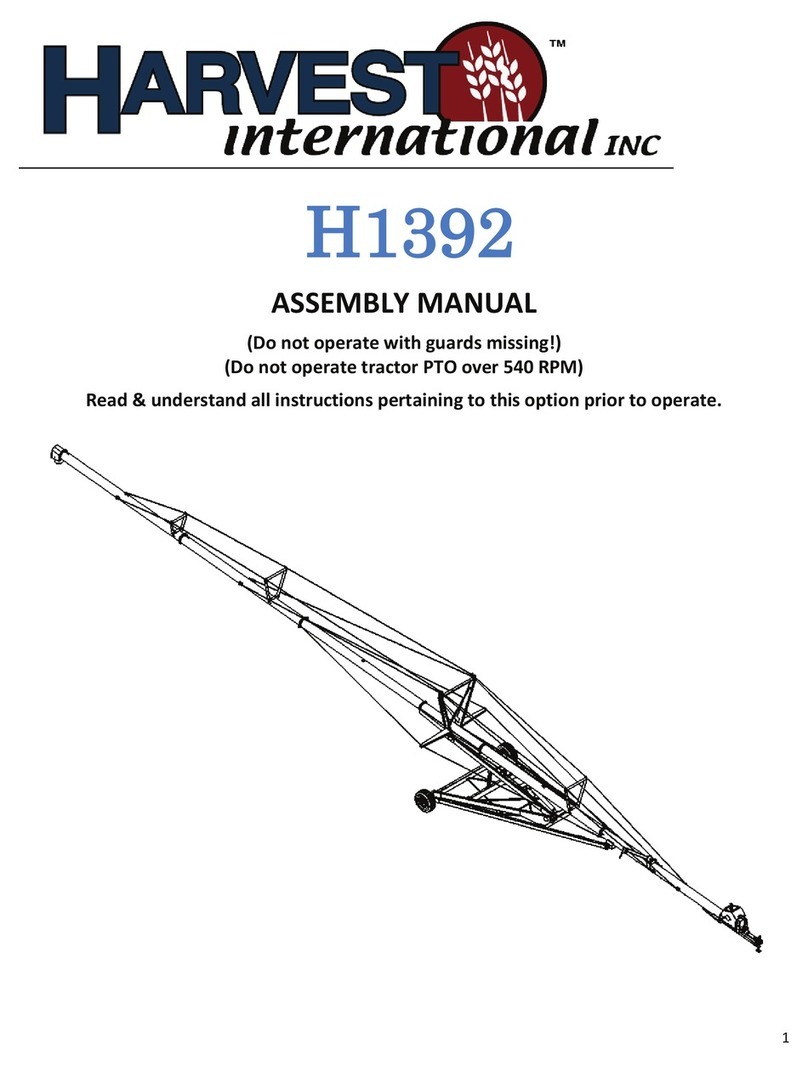
HARVEST
HARVEST H1392 User manual
HARVEST
HARVEST FC1545 User manual

HARVEST
HARVEST A1072 User manual

HARVEST
HARVEST T1052 User manual
HARVEST
HARVEST H1394XT User manual
HARVEST
HARVEST T1342 User manual
