Tektite New Holland G6035 Series User manual
New Holland G6035 Series ROPS Cab
* G6035 shown with optional equipment *
June 2021© New Holland G6030/6035 ROPS Cab Installation Manual
New Holland G6035 Series ROPS Cab
This ROPS cab is designed and built to fit the New Holland G6030 and G6035.
Designed and Built by:
Tektite Manufacturing Inc:
427 Buffalo Street
P.O. Box 639
Winkler, MB
R6W 4A8
Canada
PH: 204-331-3463
Fax: 204-331-4159
www.tektite.ca
One year standard product warranty provided by Tektite.

DO NOT PROCEED FURTHER UNTIL YOU HAVE READ THE INFORMATION BELOW
1) Always wear personal protective equipment
2) A minimum of two people is necessary to safely install the cab
3) This ROPS cab is heavy. A lift assist device such as an overhead
hoist or high lift forklift is required.
4) Ensure your work area is well ventilated. The installation
requires the starting of the tractor which will produce
dangerous carbon monoxide fumes.
5) Read through the entire installation manual first.
6) Follow the installation instructions in order.
7) Reading the operators manual prior to using the ROPS cab.

Tektite Manufacturing Incorporated thanks you for purchasing a New Holland G6035 series
ROPS cab! Tektite has worked very hard to design and build this ROPS product and we hope
that it provides you with many years of ROPS protection.
Tektite’s ROPS products are designed to provide safe and dependable service during operation
when they are properly maintained according to the instructions. Please read this installation
manual carefully before installing and using this ROPS product.
The photos/illustrations provided in this manual may not provide all the detail needed, and are
for reference only.
All directions provided are from the reference point of the mower seat facing the steering
wheel. All left and right references are from this view point.
For reference, please fill in the information below. This will assist your dealer in providing
service for this ROPS. It is advisable that this information be provided to your insurance
company as well in the event that the tractor is lost or damaged.
Vehicle Model: _________________________________________________________
ROPS Serial Number: ___________________________________________________
Date of Purchase: _______________________________________________________
Dealer Name: ___________________________________________________________
June 2021© New Holland G6030/6035 ROPS Cab Installation Manual

Parts List Standard Cab:
Description
Qty
Structural Washer, ¼” thick
4
Chassis Isolator, Rubber, 5/8” (pre-installed)
4
Bolt, Hex, 5/8” x 5”, Gr. 8, YD
4
Nut, Flange, 5/8”, Gr. 8, YD
4
Rear Cab Shield (pre-installed)
1
Bolt, Hex, ½” x 4 ½”, Gr. 8
2
Cab Lift Brackets
2
Fir Tree Fasteners
7
Left Tank Seal Floormat
1
180° Weather stripping
6 ½”
90° Weather stripping
5 FT
Wire Loop, 1/4”
2
Parts List Optional Components:
Heater
Description
Qty
Straight fitting, 3/8NPT x 3/8” barb
1
Elbow fitting, 3/8NPT x 3/8” barb
1
Grommet, 1” hole, 3/8” hose
4
HS-6 hose clamps
2
Zip Ties, Standard
6
3/8” ID heater hose (installed on cab)
22’6”
Air Conditioner
Description
Qty
Compressor, Top Port
1
Compressor Mounting Bracket
1
Alternator Stiffener Bracket
1
Alternator Mount Bracket
1
Compressor Tensioner Bracket
1
Belt, 31/64” x 40 3/8” (25-9400)
1
Belt, 31/64” x 52 3/8” (25-9520)
1
Bolt, Flange, 5/16” x 1 ½”
4
Nut, Flange, 5/16”
4
Nut, Flange, 3/8”, YD
3
June 2021© New Holland G6030/6035 ROPS Cab Installation Manual

Bolt, Flange, 3/8” x 1 ½”, YD
3
Wire, Red, 10GA with ¼” Yellow Ring on one end
54”
Wire, Red, 16GA
50”
Wire, Black, 16GA with Ring on one end
51”
Wire, Orange, 16GA
50”
Loom, 1/2"
52”
Zip Ties, Standard
6
Shrink wrap for Wire, 1” long
6
Bullet, Female, Blue
1
June 2021© New Holland G6030/6035 ROPS Cab Installation Manual

If cab is equipped with air conditioning option, the following steps can be performed before the
cab is installed.
Air Conditioner Installation Instructions:
1. Disconnect the battery ground. Disconnect the wire harness plugging into the alternator.
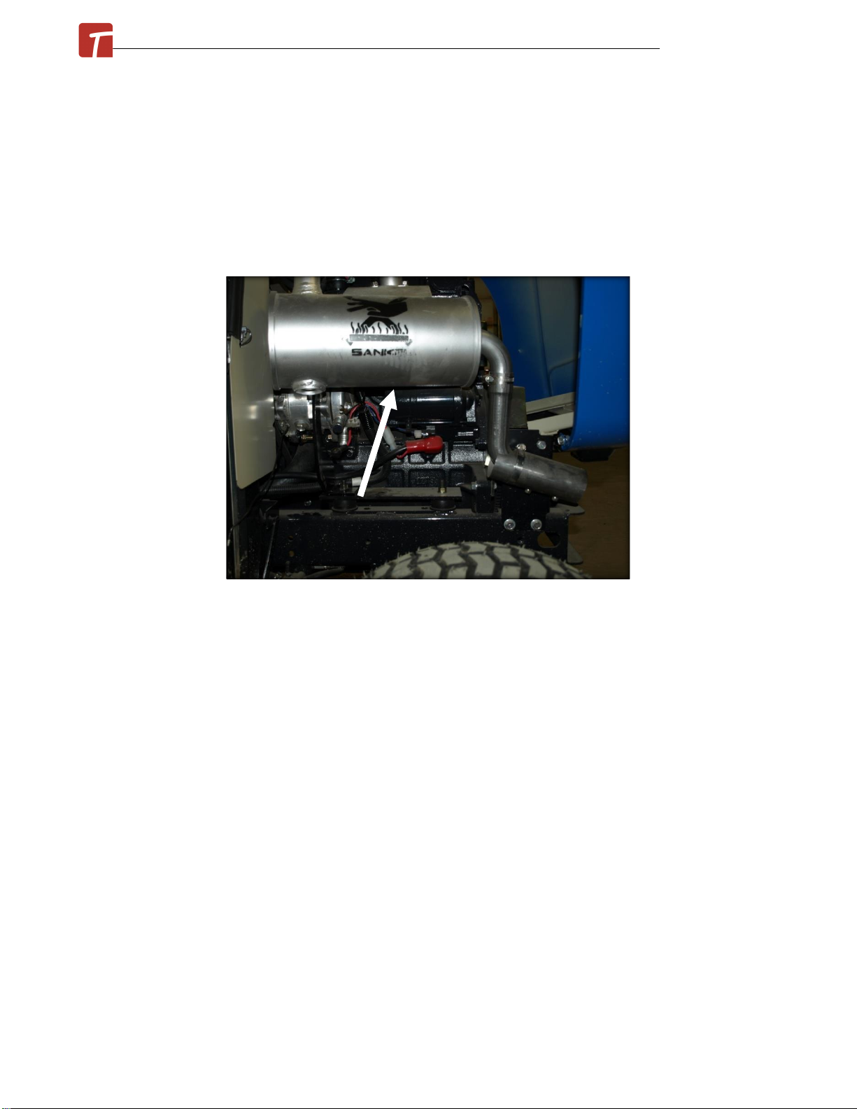
2. Remove the muffler assembly to provide better access.
3. Take off main drive shaft from motor and remove drive belt.
4. Un-bolt and remove the alternator from the alternator bracket, and then un-bolt the
alternator bracket from the engine.
5. Take the provided compressor mounting bracket and bolt onto engine where the alternator
bracket used to be installed. Use the original alternator bracket fasteners.
6. Take the compressor and two of the 3/8” x 1 ½” flange bolts and nuts and loosely bolt the
compressor to the mounting bracket installed earlier. Ensure that the fittings will be pointed as
shown in the photo and the compressor is rotated to the position that is shown.
June 2021© New Holland G6030/6035 ROPS Cab Installation Manual
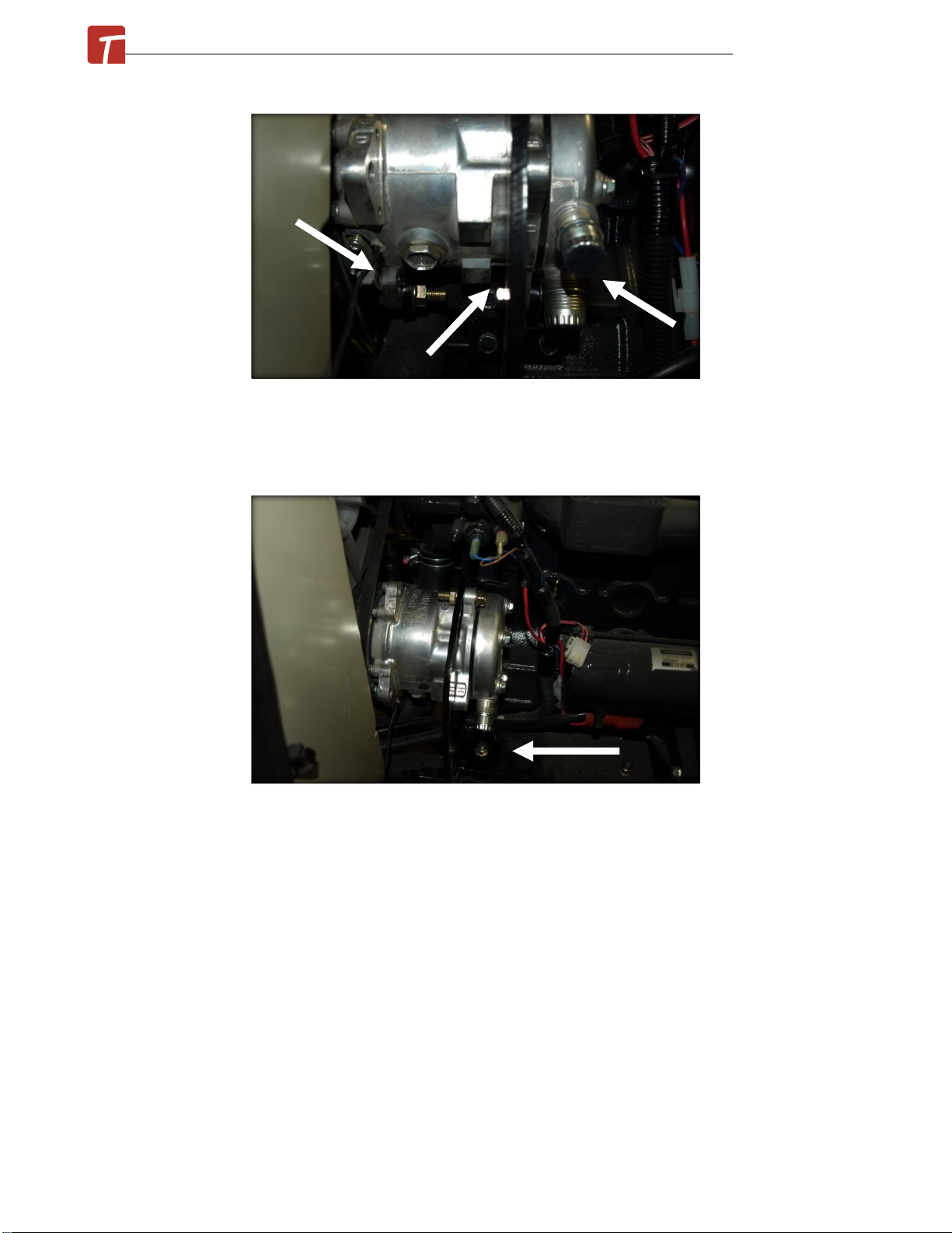
7. Remove the front engine mount nut on the left side of the engine. Take the provided
compressor tensioning bracket, slide onto bolt, and then use the front engine mount bolt to
fasten into place.
8. Take one of the 3/8” x 1 ½” flange bolts and nuts and loosely attach the tensioning bracket to
the compressor. See previous photo.
9. Take the provided 31/64” x 40 3/8” main drive belt and slip over the main drive, fan and
compressor pulleys. This belt can be fully tensioned at this point. Tighten all fasteners once
proper tension has been applied.
June 2021© New Holland G6030/6035 ROPS Cab Installation Manual

10. The harness wires going to the alternator all need to be extended as the alternator is
moving to the right side of the engine. Use the provided red to red with white stripe, orange to
pink and black to black, 16 GA wires along with the red 10 GA wire. Cut, solder, and wrap the
extension pieces in, one wire at a time.
11. Remove both of the nuts on the right engine mount bracket and slide the ground strap up
off of the front bolt.
12. Take the alternator mount bracket and slide onto both of the bolts sticking through the
engine mount plate. Re-install the ground strap under the front nut. Use factory nuts to fasten
into place. See previous photo.
June 2021© New Holland G6030/6035 ROPS Cab Installation Manual
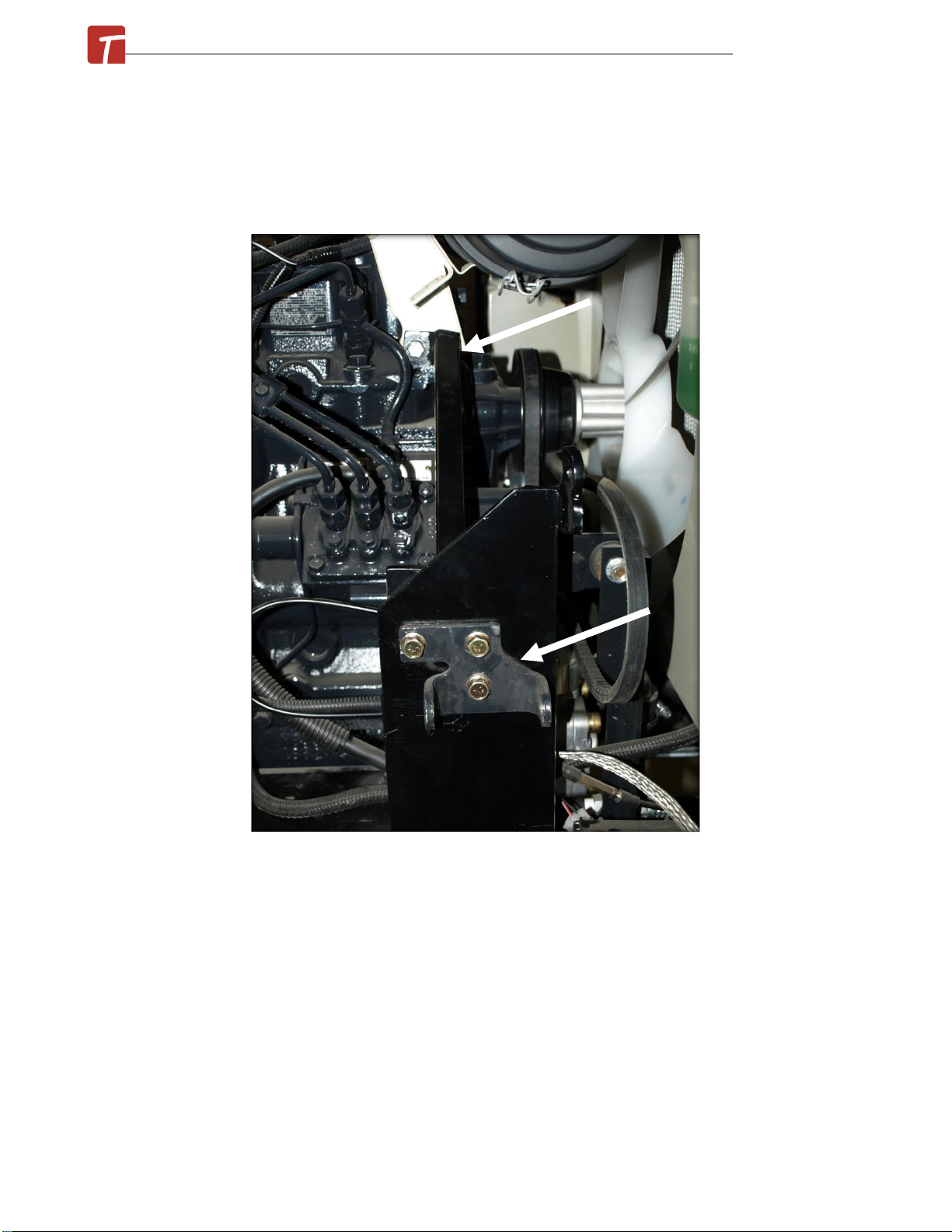
13. Take the alternator stiffening bracket, the original alternator mounting bracket and three
provided 5/16” x 1 ½” flange bolts and nuts. Slide the bolt through factory alternator bracket,
through the new mount bracket, and then through the stiffening bracket. The stiffening
bracket will attach higher up at the air cleaner mount.
14. Remove the lower bolt fastening the air cleaner bracket to the engine. Fasten the
alternator stiffener bracket with this bolt. See previous photo.
15. Loosen and remove the upper rubber engine mount on the right side of the engine in order
to allow the alternator belt to be slipped through for half of it. Once the belt is past, re-fasten
into place.
June 2021© New Holland G6030/6035 ROPS Cab Installation Manual
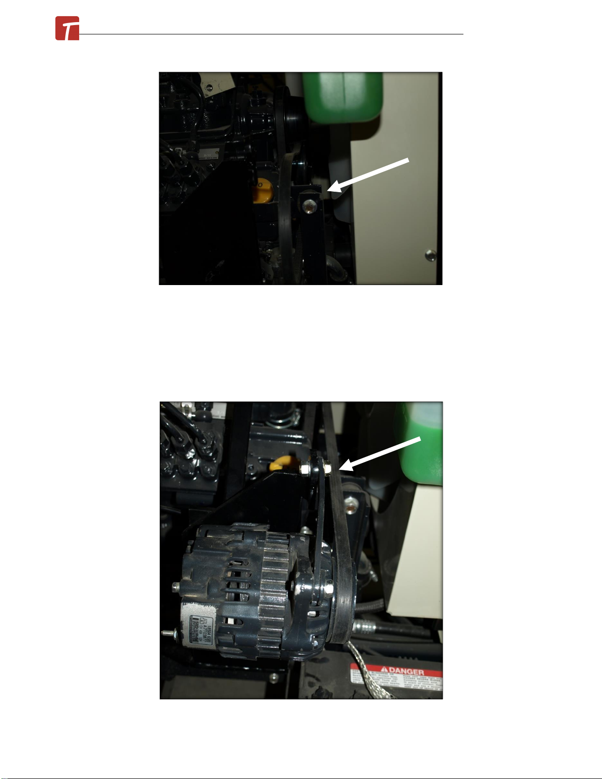
16. Take the alternator tensioner bracket removed earlier and fasten to the top ear on the
alternator with the factory bolt used.
17. Take the alternator and factory fasteners, and fasten it to the mounting plate on the factory
mounting bracket re-installed earlier, and then to the tensioner bracket installed on the
previous step.
June 2021© New Holland G6030/6035 ROPS Cab Installation Manual
18. Slide the alternator drive belt to the compressor and over the alternator. Apply tension to
the belt and firmly fasten all bolts. See previous photo.
19. Re-connect the engine drive shaft.
20. Re-connect the wiring harness onto the alternator.
21. Re-install the muffler.
Cab installation can now begin.
Cab Installation Instructions:
1. Remove the upper 2-post ROPS hoop structure.
2. Tilt the seat box forward. Take the provided 90° bulb seal weather stripping, and install
along the outside edge of the seat box so that the bulb is facing towards the outer tanks.
3. Take the provided left tank panel floormat piece, along with the Christmas tree fasteners
provided. Slide the floormat through the control levers in the left tank and slide mat down
onto tank. Use the fasteners provided and push them through the floormat and into the tank.
June 2021© New Holland G6030/6035 ROPS Cab Installation Manual

4. Take the provided 6 ½” piece of 180° weather-stripping and install onto the inside edge of
the outer control cut-out on the right side tank.
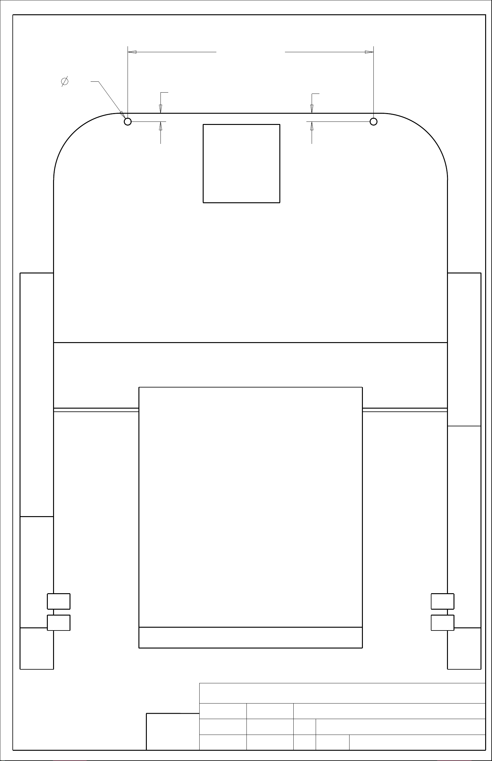
5. Use the schematic on the following page to drill two 5/8” holes into the tractor platform.
< see schematic next page >
June 2021© New Holland G6030/6035 ROPS Cab Installation Manual
Notice of Confidentiality
This material is property of Tektite Manufacturing
Inc and is not to be used by the recipient for any
purpose other than the purpose for which it was
transmitted. The material remains the property of
Tektite and shall be returned upon request. The
material may not be reproduced or disclosed to third
parties without the written consent of Tektite.
Tolerances:
Unless otherwise
specified
X.X = ± 1/16"
Angular = ± 1.0 °
Drawn By:
Checked By: Size:
File Name:
Units:
Date:
Date:
Req'd: Description:
Tektite Manufacturing Inc.
24157 Hwy 3, Box 639, Winkler MB, R6W 4A8, Canada
22
On Centre
of Platform
3/4
3/4
2 holes
5/8
Hole Drilling Schematic
Daryl Furkalo
2011-10-06 Imp.
B
SCALE 0.250

6.Return to the cab to install lift brackets next. To remove the gas shock on the left cab door,
slide a flat screwdriver underneath the small clip on the end cap that must be pulled UP order
to pop the shock off of the ball stud. The shock will release very easily when this is
accomplished. Lift the door assembly straight up and off of the cab and put aside for now.
Repeat for the right door.
7. Take the cab lift brackets along with the ½” x 4 ½” hex bolts. Position the lift bracket against
the mount plate in the upper corner of the door and fasten into place for both brackets.
8. Use a lift strap or chain and tie the two lift brackets together. Connect to a forklift or an
overhead hoist and prepare to lift cab off of shipping pallet. Un-bolt the cab shipping brackets
from the cab and then lift cab up.
9.Position the cab over top of the mower. Carefully lower the cab down onto the mower until
the rear mount hole aligns with the lower hole in the lower 2-post ROPS bent plates, and the
front isolator is touching the floor platform at the front. Use the 5/8” x 5” hex bolt, heavy ¼”
thick flat washer, and flange nut for the ROPS isolator fasteners. Get all started before applying
any finally torques.
10. Once all fasteners are started remove lift brackets and straps from the cab. The 5/8”
fasteners can have 205 ft-lbs torque.
11.Route the wiring harness, located at the bottom of the left C-post, underneath the hood.
Locate the starter and connect the heavy red wire to the constant 12v source with the provided
June 2021© New Holland G6030/6035 ROPS Cab Installation Manual
1/4" loop. Shorten the wire if necessary, then solder the connector to the red wire. Connect
the orange wire to a switched source, solder directly to engine wire. Connect the heavy black
wire to a ground bolt at the back of the starter with the provided 1/4" loop. Shorten wire if
necessary, then solder the connector to the black wire.
If cab is equipped with heater, proceed with the following steps.
12. Un-latch and open hood.
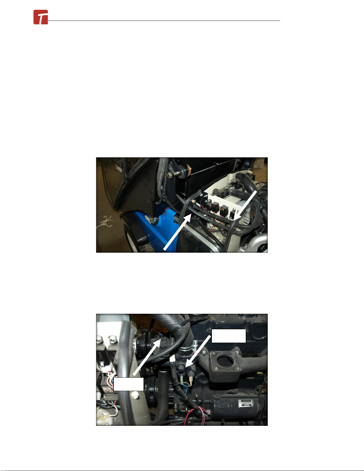
13. On the left front side, four holes need to drilled into the sheet metal panels in order to run
heater hose through grommets and into the engine bay. Mark and drill four 1” holes into the
panels shown. Install the provided grommets into the holes.
14.Drain the engine coolant.
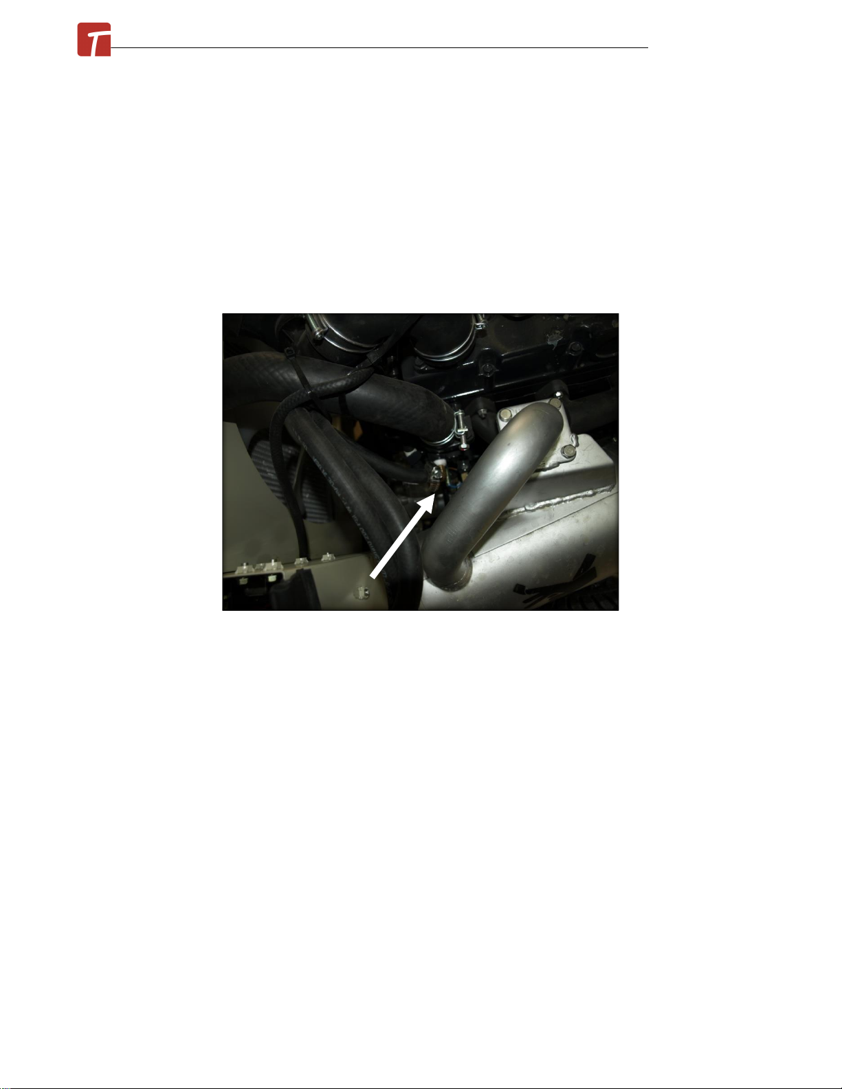
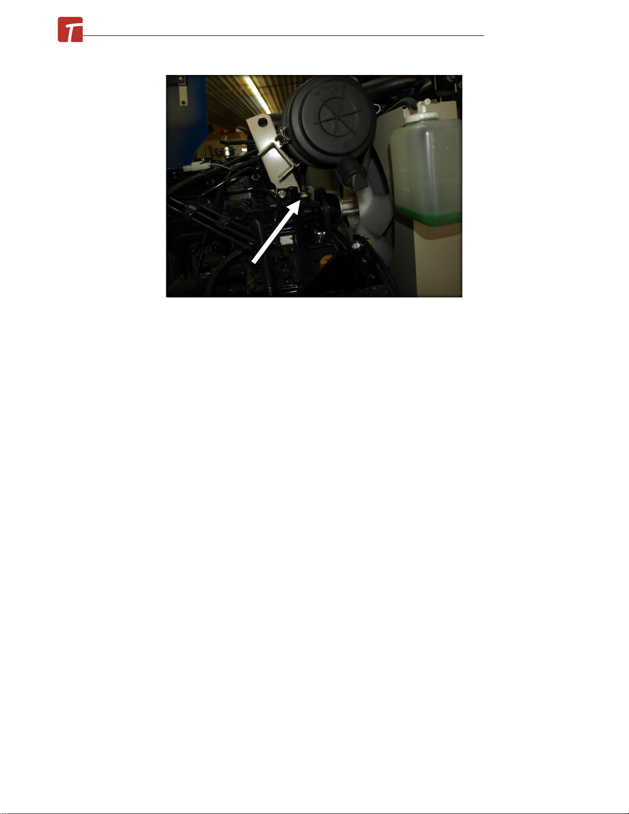
15.The pressure fitting is located on the left side of the engine. Remove the plug shown. Use
water sealant material around the threads of the fitting to prevent water leaks. Use the 3/8NPT
x 3/8” barb elbow fitting and screw it into the open port. This is the PRESSURE fitting.
Pressure
Suction
June 2021© New Holland G6030/6035 ROPS Cab Installation Manual
16. Locate the plug on the top of the water pump roughly on centre the engine shown in the
previous photo. Take the 3/8NPT x 3/8” barb straight fitting and screw it into the open port.
This is the SUCTION fitting.
17. Locate the hoses on the left rear of the cab, the PRESSURE hose is the one that is nearest to
the rear window glass. Route the hoses underneath the hood and into the engine bay. Use zip
ties to attach the hoses to the tractor to prevent the hose from contacting moving parts on the
engine. Cut the hose and then connect it to the pressure fitting. Use zip ties to tidy up the
hose. Use the provided HS-6 hose clamps to secure the hose to the fitting.
18. Route the other hose to the suction fitting, ensuring that it does not interfere with any
moving parts. Cut any excess length, and connect to the suction fitting with the provided HS-6
hose clamps.
June 2021© New Holland G6030/6035 ROPS Cab Installation Manual
19. Make sure all fitting connections are tight and the hoses are properly secured to the
machine. Re-fill the engine antifreeze. Go to the cab, and turn the heater control switch to the
maximum heat side. Start the engine and turn the cab fan to the highest speed setting. Take
the radiator cap off of the engine and place a funnel into the radiator. Fill the funnel with
antifreeze. The engine will need to run for a few minutes and the thermostat open a few times
in order for all air to be purged from the heater system. The air at the cab louvers should be
very hot when that occurs. NOTE: ensure adequate fresh air ventilation in the work space you
are in, carbon monoxide from the engine exhaust is deadly.
20.To ensure a better seal of all weather stripping and floor mat pieces, it is recommended that
you use a black silicone seal to seal the cab parts to the tractor.
21. Take the step removed at the start of the install and fasten to the two tabs that are on cab,
below the left door opening. Use the factory step hardware.
June 2021© New Holland G6030/6035 ROPS Cab Installation Manual

For cabs equipped with air conditioning option, proceed with the following steps.
NOTE: With the compressor orientated the way it must be in this design, ALL of the pre-filled
oil in the compressor WILL pour out.
22. Take the hoses from the right C-post baffle, and route underneath the hood towards the
compressor.
23. Connect the # 10 hose to the #10 fitting on the compressor. Ensure O-ring is properly
seated!
24. Connect the # 8 hose to the # 8 fitting on the compressor. Ensure O-ring is properly seated!
25. Use the provided zip ties to tie the hoses into place and prevent them from contacting any
moving parts or hot surfaces.
26. Take the white wire that was with the air-conditioner hoses, along with the provided bullet
connector and connect the wire to the compressor clutch wire on the compressor. Shorten
wire as necessary.
27. Air conditioning system is now ready to be charged by a licensed air conditioning install
technician. The compressor is normally pre-filled with oil and should have 3.5 fluid oz of SP15.
The system requires 2 lbs of R-134a refrigerant. NOTE: With the compressor orientated the
way it must be in this design, ALL of the pre-filled oil in the compressor WILL pour out.
June 2021© New Holland G6030/6035 ROPS Cab Installation Manual
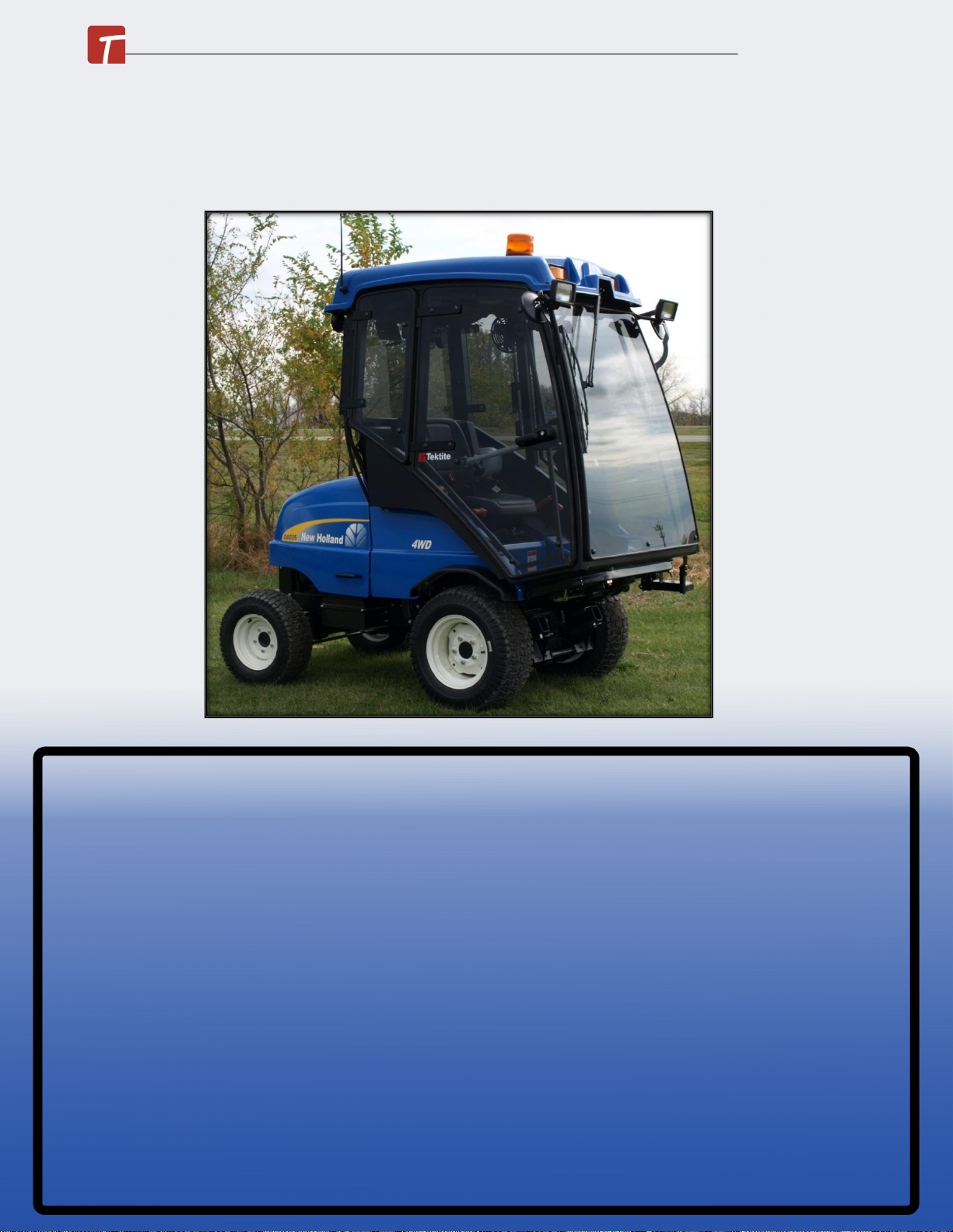
New Holland G6035 Series Cab
* G6035 model Shown with optional equipment *
June 2021© New Holland G6035 Series ROPS Cab Operation Manual
New Holland G6035 Series Cab
This ROPS cab is designed and built to fit the New Holland G6030 and G6035.
Designed and Built by:
Tektite Manufacturing Inc:
427 Buffalo Street
P.O. Box 639
Winkler, MB
R6W 4A8
Canada
PH: 204-331-3463
Fax: 204-331-4159
www.tektite.ca
One year standard product warranty provided by Tektite.

Tektite Manufacturing Incorporated thanks you for purchasing a New Holland G6035 series
ROPS cab! Tektite has worked very hard to design and build this ROPS product and we hope
that it provides you with many years of ROPS protection.
Tektite’s ROPS products are designed to provide safe and dependable service during operation
when they are properly maintained according to the instructions. Please read this operator
manual carefully before using this ROPS product.
The photos/illustrations provided in this manual may not provide all the detail needed, and are
for reference only.
All directions provided are from the reference point of the tractor seat facing the steering
wheel. All left and right references are from this view point.
For reference, please fill in the information below. This will assist your dealer in providing
service for this ROPS. It is advisable that this information be provided to your insurance
company as well in the event that the tractor is lost or damaged.
Vehicle Model: _________________________________________________________
ROPS Serial Number: ___________________________________________________
Date of Purchase: _______________________________________________________
Dealer Name: ___________________________________________________________
June 2021© New Holland G6035 Series ROPS Cab Operation Manual
This manual suits for next models
2
Table of contents
Other Tektite Farm Equipment manuals


Popular Farm Equipment manuals by other brands

hydrofuse
hydrofuse Fertilizer Machine V1.3 installation manual

GREAT PLAINS
GREAT PLAINS Turbo Max 1800TM Assembly manual

Gaspardo
Gaspardo M 250 Use and maintenance

Land Pride
Land Pride RCF3684 Operator's manual

Jay-Lor
Jay-Lor 3350 Operator's manual

VOSS.farming
VOSS.farming XTREME duo RF instruction manual


VEVOR
VEVOR TM-5 user manual

MECHANICAL TRANSPLANTER
MECHANICAL TRANSPLANTER 5500WD Assembly and operators manual

Krone
Krone Swadro TC 680 Original operating instructions

horsch
horsch Tiger AS Series operating instructions

Titan Attachments
Titan Attachments PRO Series Operator's manual

Mepu
Mepu Major 2000 user manual