HARWI 130 User manual

1
MANUAL
130
Harwi Holland BV
Lage Dijk 28
5705 BZ Helmond
the Netherlands
Tel. 31 (0) 543355
Fax 31 (0) 522305
Email inf[email protected]l

2
CONTENTS
APPLIANCE ........................................................................................................................................................................... 3
GENERAL INDICATIONS/SAFETY REGULATIONS ............................................................................................................... 4
GENERAL INFORMATION ..................................................................................................................................................... 5
MANUFACTURER.............................................................................................................................................................. 6
MACHINE........................................................................................................................................................................... 6
EU DECLARATION OF CONFORMITY FOR MACHINERY................................................................................................. 6
SPECIFICATIONS.................................................................................................................................................................. 7
NOISE INFORMATION ...................................................................................................................................................... 7
SETTING UP THE MACHINE ................................................................................................................................................. 8
MOVING ............................................................................................................................................................................ 8
INSTALLING THE MACHINE.............................................................................................................................................. 8
DUST EXTRACTION.......................................................................................................................................................... 8
CONNECTING THE ELECTRIC SUPPLY ............................................................................................................................... 9
MACHINE CONNECTION .................................................................................................................................................. 9
DIRECTION OF SPINDLE ROTATION ................................................................................................................................. 10
PROPER DIRECTION IS CLOCKWISE............................................................................................................................ 10
WRONG DIRECTION IS ANTI CLOCKWISE.................................................................................................................... 10
CHANGING THE SAW-BLADE............................................................................................................................................. 11
ADJUSTING THE RIVING KNIFE ......................................................................................................................................... 12
OPERATING THE MACHINE................................................................................................................................................ 13
RIPPING .......................................................................................................................................................................... 13
MITRING WITH THE MITRE FENCE................................................................................................................................ 14
HEIGHT ADJUSTMENT SAW-BLADE.............................................................................................................................. 15
ANGLE ADJUSTMENT SAW-BLADE ............................................................................................................................... 15
FINE ADJUSTMENT......................................................................................................................................................... 15
MALFUNCTIONS ................................................................................................................................................................. 16
SAW CUT IS NOT SQUARE (ADJUSTING 0°STOP)................................................................................................... 16
SAW CUT IS NOT 45°(ADJUSTING STOP 45°) .......................................................................................................... 16
RIP FENCE NOT PARALLEL TO SAW-BLADE. ............................................................................................................... 17
WOOD CLAMPS BETWEEN FENCE EN SAW-BLADE. ................................................................................................... 17
WOOD CLAMPS ON RIVING KNIFE................................................................................................................................ 18
BRAKE DOES NOT WORK.............................................................................................................................................. 18
SAW-BLADE DOES NOT ROTATE .................................................................................................................................. 18
MAINTENANCE.................................................................................................................................................................... 19
CLEANING, LUBRICATING AND GREASING .................................................................................................................. 19
40 PRODUCTIVE HOURS ........................................................................................................................................... 19
160 PRODUCTIVE HOURS.......................................................................................................................................... 19
1000 PRODUCTIVE HOURS........................................................................................................................................ 19
WIRING DIAGRAM .............................................................................................................................................................. 20

3
APPLIANCE
The sawbench type 130 is only to be used for
cutting wood and wood-like panels (e.g.
chipboard, block board, MDF etc.)
Maximum panel sizes:
Height: 110 mm
Between saw-blade and
rip fence: 1250 mm
Length (not supported): 1000 mm
Cutting of other materials with the standard
saw-blade is prohibited. Cutting other materials
with a special saw-blade only with permission of
manufacturer.
All other appliances except for the above are
improper use of the machine and therefore
prohibited. The producer cannot be held
responsible for damage as a result of improper
use. Damage will be recovered from the user
The machine may not be operated, used or
maintained by persons not acquainted with the
risks of the machine.
Permission for operating, using and maintaining
the machine have to be clearly described by a
person or persons responsible within the
organisation.
Maintenance has to be performed by the
manufacturer or customer service.
One has to be acquainted and comply with the
country's applicable safety regulations.
Only original Harwi parts are to be used.
We cannot give warranty or be held responsible
for damage caused by using non-original Harwi
parts.
The manufacturer cannot be held responsible
for damage caused by changes made to the
machine by the user.
REMAINING RISKS
If the machine is completely used according
to all safety regulations there still will
remain some risks:
Touching of the saw-blade with the
sawing area.
Touching of the saw-blade when the lid is
opened
Breaking of the saw-blade or parts of the
saw-blade hurtling out of the guard.
Touching of parts under voltage while
junction box or switch is opened.
Damage to the hearing by constant use
of the machine without ear protection.
Throw out of harmful dusts or vapours by
using a dust extractor with bad
performance or no dust extractor at all.

4
GENERAL INDICATIONS/SAFETY REGULATIONS
Harwi Holland B.V. has bestowed great care
on compiling this manual. Before operating the
machine read the complete manual carefully.
Persons under the age of 18 are not allowed to
work on or with circular sawing machines.
Except for a training program on a legal basis.
The machine may only be operated by
educated personnel or under supervision of
educated personnel.
To avoid touching with rotating saw-blades
make sure that:
Clothing fits tightly to the body
Work with closed fingers
No rings or other jewellery are worn.
A hairnet is used by long hair.
Be careful when changing the saw-blades.
They are sharp and cause injuries.
Do not remove woodchips when the saw-blade
is running. Stop the machine first.
Broken saw-blades or blades or deformed
blades are not to be used. Neither are HSS
blades
The applied saw-blade is to be used and
sharpened according to the directions of the
manufacturer.
Sharpening only by competent craftsmen.
Stick to max. admissible r.p.m. mentioned on
the blade. Preferably use noise-reduced saw-
blades.
Flexible hoses of the dust extractor have to be
from a highly inflammable quality (according to
DIN 4102).
The safety guard and other safety equipment
may not be removed or put out of order.
Assembling or repairs are only to be performed
if the machine cannot be switched on. The
switch or the main switch are to be switched off
and locked with for instance a padlock.
Repairs to the electricity supply are only to be
executed by skilled craftsmen.
When leaving the working area make sure that
incompetent persons cannot switch on the
machine. It is obligatory to wear dust-mask, ear
protection and safety glasses.
Take care of a clean working area.
The machine has to be lighted. When using
strip lighting take into account the stroboscopic
effect. A rotating saw-blade seems to be
standing still.

5
GENERAL INFORMATION

6
MANUFACTURER
HARWI Holland B.V.
Lage Dijk 28
5705 BZ Helmond, the Netherlands
Tel: 00 31 492-54 33 55
Fax: 00 31 492-52 23 05
MACHINE
Sawbench
Type:.....................................................
Machine number:..................................
Manufactured:......................................
EU DECLARATION OF CONFORMITY FOR MACHINERY
(according to Annex II A of the Machinery Directive)
We HARWI Holland B.V. Lage Dijk 28, 5705 BZ Helmond, the Netherlands herewith declare, on our
own responsibility, that the product:
HARWI SAWBENCH TYPE 130, MACHINE NUMBER..........................,
which this declaration refers to, is in conformity with the following standards;
2006/42/EG meets requirements EMV 2004/108/EG.
Meets requirements, resulting from supplement 4 of the Machinery directive, against
Holz – BG 0392
For Construction and Building EN-1870-1
Netherlands, Helmond, d.d.
……………………………………name
…………………………………….signature

7
SPECIFICATIONS
MEASURES AND WEIGHTS
Height of cut (standard) mm
0-110
Height of cut (max.)
mm
135
Width of cut mm
625 of 1250
Diam. saw-blade (standard) mm
∅
400
Diam. saw-blade (max.) mm
∅450
Saw-blade bore mm
∅
30
Angle adjustment
0-45°
Distance saw-blade centre to
front table
mm
580
Table size
mm
965*1125
Table height
mm
850
Motor power kW
5.5
hp
7.5
Voltage V
380
Spindle speed
rpm
2800
Weight
kg
320
Used saw-blades have to be conform to prEN 847-1.
Maximum thickness of saw-blade 3.6 mm.
NOISE INFORMATION
Used saw-blade: :Leuco proline 101420/10005 ∅400
Z=48 d=30.
A-weighed Equivalent Continuous Noise Pressure
Idle dB(A) :81.0 dB(A)
Loaded dB(A) :84.4 dB(A)
Measuring performed according to DIN 45635 part 1659. Measured when cutting chipboard thickness
18 mm, length 2 meters.
Safe deviation can be approx. 3 db(A).
The above-mentioned values are radiated noise pressures and not necessarily noise pressures to
work safely with this machine. Supplementary measures for ear protection can be necessary. The
following can be of influence:
duration of operations
working area
other noises
Maximum value may vary per country. Above information can be used for better valuation of dangers
and risks subsequent to using this machine.

8
SETTING UP THE MACHINE
MOVING
Move the machine with a forklift truck or a
pallet truck with forks of max. 550 mm and a
minimum length of 600 mm (Fig. 1). Minimum
capacity of 500 kilograms. Put the forks at the
left side far enough under the machine to avoid
tilting.
INSTALLING THE MACHINE
The machine has to be put on a solid floor,
which has to be flat, dry and not slippery.
DUST EXTRACTION
The machine has to be connected to a dust
extraction.
Connection for dust extracting hose of ∅120
mm. Connection of the safety guard is ∅80
mm.
The extracting capacity has to be calculated in
such a way that a minimum air speed of 20 m/s
is reached at the connection. Air speed is 1500
m3 at a depression bigger than 450 Pa.
Figure 1
45
40
35
30
25
20
15
10
5
0

9
CONNECTING THE ELECTRIC SUPPLY
A skilled craftsman may only do connecting the
machine.
MACHINE CONNECTION
380 V- 3 PHASE
(see wiring diagram)
1 Disconnect mains supply.
2 Open switch at the backside of the
machine (fig. 2).
3 Connect the 5-core cable at the same
points.
Black (1] = Phase
Black [2] = Phase
Brown [3] = Phase
Bleu [4] = Zero
Yellow/green [5] = Earth
the 3 phases L1. L2, L3
- MP for the zero
- PE for the earth
4 Close the switch.
Notice: Use cartridge fuses of min. 25 Ampere.
Notice: Check the rotation of the saw (see
chapter DIRECTION OF SPINDLE
ROTATION).
Figure 2

10
DIRECTION OF SPINDLE ROTATION
Disconnect the mains supply with the main
switch at the backside of the machine.
Remove the table insert, the saw nut, the
flanges and the saw-blade (see chapter
CHANGING THE SAW-BLADE).
0 Put the motor in the highest position.
PROPER DIRECTION IS CLOCKWISE
(Looking from the front side of the spindle to the
motor, fig. 3).
1 Connect the mains supply.
2 Switch motor on and off.
3 Check if direction is clockwise.
4 Disconnect the mains supply with the
main switch.
5 Put saw-blade, flanges and saw nut back
(see chapter CHANGING THE SAW-
BLADE).
6 Put table insert back.
WRONG DIRECTION IS ANTI
CLOCKWISE
(Looking from the front side of the spindle to the
motor fig. 3).
1 The spindle turns anti clockwise.
2 Disconnect the mains supply.
3 Open the switch at the backside of the
machine and interchange two phases.
4 Check the rotation again.
5 Disconnect the mains supply with the
main switch.
6 Put the saw-blade, the flanges and the
saw nut back on.
7 Put table insert back.
Figure 3

11
CHANGING THE SAW-BLADE
Notice: Before changing the saw-blade
disconnect the main switch at the backside
of the machine and secure it against
switching on with a lock.
Noise reduced saw-blades are preferred. Use
a suitable saw-blade. Enquiries at you supplier
or the manufacturer.
1 Remove the table insert with the 4 mm
Allen key..
2 Block the saw-blade with the spanner at
the front side of the saw spindle (fig.4 ).
3 Remove the flange.
4 Remove the saw-blade.
5 Clean the flanges, the thread of the
spindle and the nut.
6 Put the saw-blade and flange back again.
Notice: spindle rotation is clockwise.
7 Check the position and the thickness of
the riving knife.
8 Put the table insert back.
Saw-blades have to be sharpened by experts.
Figure 4

12
ADJUSTING THE RIVING KNIFE
Check the thickness and the measures of
the riving knife. The riving knife has to be
thicker than the blade body but thinner than
the tooth thickness.
1 Disconnect the mains supply at the main
switch and secure it against switching on.
2 Remove the table insert.
3 Put the saw-blade in its highest position.
4 Loosen the bolt of the riving knife
fastening.
5 Adjust the riving knife in such a way that
the distance between the knife and the
teeth sticking out above the tabletop is
maximum 3 mm. The highest point of the
riving knife has to be 3-5 mm under the
highest point of the teeth (fig. 5).
6 Fasten the bolt of the riving knife
fastening tightly.
7 Put the table insert back.
8 Connect the mains supply.
Figure 5

13
OPERATING THE MACHINE
RIPPING
SAFETY
When ripping solid wood, put the saw-blade
as high as possible. The sub-fence max. 10
mm past the point where the blade cuts the
wood at full height.
Adjusting the sub-fence properly prevents
the return shock of the wood or a part of it.
Use a push stick when cutting small wood.
Adjusting the riving knife (fig. 6).
1 Adjust the rip fence with the sub-fence at
the desired measure.
2 Check if the saw-blade can rotate freely.
3 Switch on the motor.
4 After cutting switch off the motor
immediately.
5 Remove the material after the saw-blade
has stopped.
Notice: If the saw-blade stops because of
clamping of the wood, switch off the motor.
Hold the piece of wood tightly!
Notice: Never stand in the line of the saw-
blade. In case of a return shock you might
get hit.
Figure 6
14
OPERATING THE MACHINE
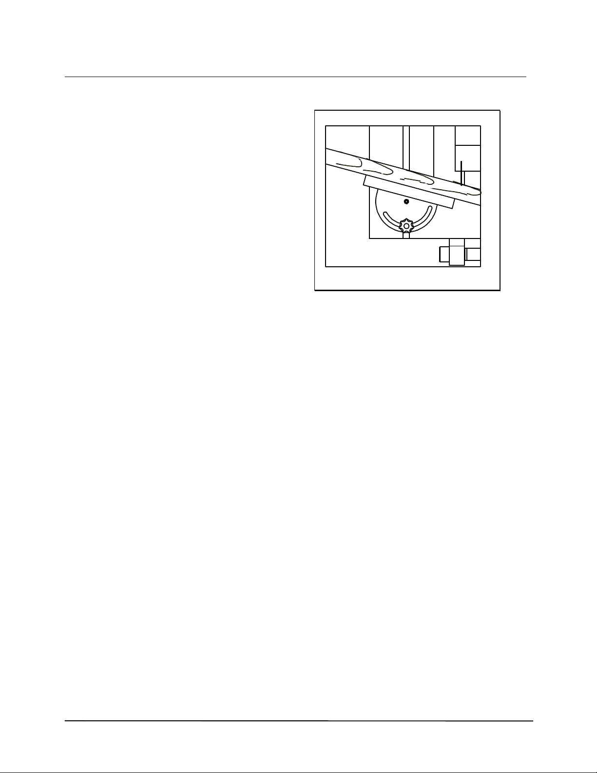
MITRING WITH THE MITRE FENCE
SAFETY
When mitring NEVER use the ripping fence
as a stop.
1 Put the saw-blade in its highest position.
2 Put the material on the machine (fig. 7).
3 Push the wood against the fence.
Notice: Support the wood properly.
4 See to it that the wood and the fence do
not touch the saw-blade.
5 Switch on the motor.
6 Move the fence and the wood forward at
a constant speed and cut the material.
7 Switch off the motor.
8 Remove the material after the saw-blade
has stopped.
Notice: If the saw-blade stops because of
clamping of the wood, switch off the motor.
Hold the piece of wood tightly!
Notice: Never stand in the line of the saw-
blade. In case of a return shock you might
get hit.
Figure 7

15
OPERATING THE MACHINE
HEIGHT ADJUSTMENT SAW-BLADE
0 The hand wheel of the height adjustment
is at the front side of the machine (fig. 8)
1 The saw-blade rises by turning the wheel
to the left (anti-clockwise).
2 The height can be adjusted accurately by
using a folding rule.
Notice: the saw-blade must have stopped.
ANGLE ADJUSTMENT SAW-BLADE
0 The hand wheel of the angle adjustment
is at the left side of the machine (fig. 9).
1 By turning the wheel to the left (anti-
clockwise the saw-blade moves from 0°to
45°.
2 Measure scale is at the front side of the
machine.
Notice: the saw-blade may not touch the
fence or the sub-fence.
FINE ADJUSTMENT
1 Adjust the rip fence at the approximately
needed measure.
2 Block the fence with the knob at the front
side.
3 Adjust the exact measure between sub-
fence and saw-blade at the left side of
the fence rail (fig. 10).
Figure 8
Figure 9
Figure 10
45
40
35
30
25
20
15
10
5
0
45
40
35
30 25 20 15

16
MALFUNCTIONS
Safety
Disconnect the machine of the mains supply
before adjusting the machine or removing
malfunctions.
See to it that all damaged parts are replaced
before operating the machine.
MALFUNCTION:
SAW CUT IS NOT SQUARE (ADJUSTING
0°STOP)
1 Put the saw-blade in its highest position
2 Set the saw-blade with a square.
3 Remove the panel at the left side of the
machine.
4 Loosen the nuts that clamp the threaded
spindle to the frame.
5 Put it against the stop fitted to the
trapezium threaded nut.
6 Fasten the two nuts tightly to the frame
(fig. 11).
MALFUNCTION:
SAW CUT IS NOT 45°(ADJUSTING STOP
45°)
1 Put the saw-blade at an angle of 45°.
2 Set the saw-blade exactly with a square.
3 Remove the panel at the left side of the
machine.
4 Adjust the nuts closest to nut with
trapezoidal thread (fig. 12).
Figure 11
Figure 12

17
MALFUNCTIONS
Safety
Disconnect the machine of the mains supply
before adjusting the machine or removing
malfunctions.
See to it that all damaged parts are replaced
before operating the machine.
MALFUNCTION
RIP FENCE NOT PARALLEL TO SAW-
BLADE.
WOOD CLAMPS BETWEEN FENCE EN
SAW-BLADE.
CHECK RIP FENCE, ADJUST AGAIN
0 Put the saw-blade in the highest position,
angle adjustment at 0°.
Example:
Distance between fence and saw-blade is
bigger at the back than at the front side of the
fence.
1 Put a wooden lath to the right side of the
saw-blade.
2 Push the fence without the sub-fence
against the lath and block the fence.
3 Loosen the right hexagon nut of the
fence with a 17 mm key.
4 Turn the right adjusting screw with an
Allen key till the fence and lath are
parallel (fig. 13).
5 Fasten the hexagon bolt tightly.
6 Check if lath and fence are parallel.
Figure 13
Example:
Distance between fence and saw-blade is
bigger at the front than at the backside.
1 Loosen the hexagon nut of the fence with
a 17 mm key.
2 Turn the left adjusting screw with an
Allen key till the fence and lath are
parallel (fig. 13).
3 Fasten the hexagon bolt tightly.
4 Check if lath and fence are parallel.

18
MALFUNCTIONS
Safety
Disconnect the machine of the mains supply
before adjusting the machine or removing
malfunctions.
See to it that all damaged parts are replaced
before operating the machine.
MALFUNCTION:
WOOD CLAMPS ON RIVING KNIFE
0 Check thickness, measure and position
of riving knife (see chapter : ADJUSTING
RIVING KNIFE).
MALFUNCTION:
BRAKE DOES NOT WORK
0 Switch off the machine and contact you
dealer or the producer how to adjust the
brake.
MALFUNCTION:
SAW-BLADE DOES NOT ROTATE
1 Disconnect mains supply.
2 Check if the saw-blade can run freely.
3 Check if the saw-blade is fitted properly
(see chapter: CHANGING SAW-BLADE).
4 Check if the saw-blade is mounted
properly between the front and back
flange.
Have you checked all this, but the problems is
not solved contact you dealer.

19
MAINTENANCE
CLEANING, LUBRICATING AND
GREASING
40 PRODUCTIVE HOURS
Perform following maintenance every 40
productive hours.
1 Clean the tubes of the height adjustment
and also the spindle. Lubricate slightly.
2 Clean the rail fence and the knob of the
fine adjustment.
3 Clean the spindle and the stop of the
angle adjustment. Lubricate slightly.
4 Brush the air inlet and parts of the motor
and check if it is not obstructed.
5 Remove plates at front and back side of
table. Clean segments and blow clean.
Lubricate slightly. Mount plates again.
160 PRODUCTIVE HOURS
Perform following maintenance every 160
productive hours.
5 Wear and tear of cables.
6 Broken or torn parts of the electric circuit.
7 Brake time of saw-blade (has to be less
than 10 seconds).
8 Operation and condition of safety guard.
9 Free outlet of dust collector to dust
extractor.
1000 PRODUCTIVE HOURS
Perform following maintenance every 1000
productive hours.
10 The bolt connections of the height and
angle adjustment.
11 Check saw spindle for backlash.
12 The bolt and nut connections of the
motor.

20
WIRING DIAGRAM
The diagram is in the switchbox
Table of contents


