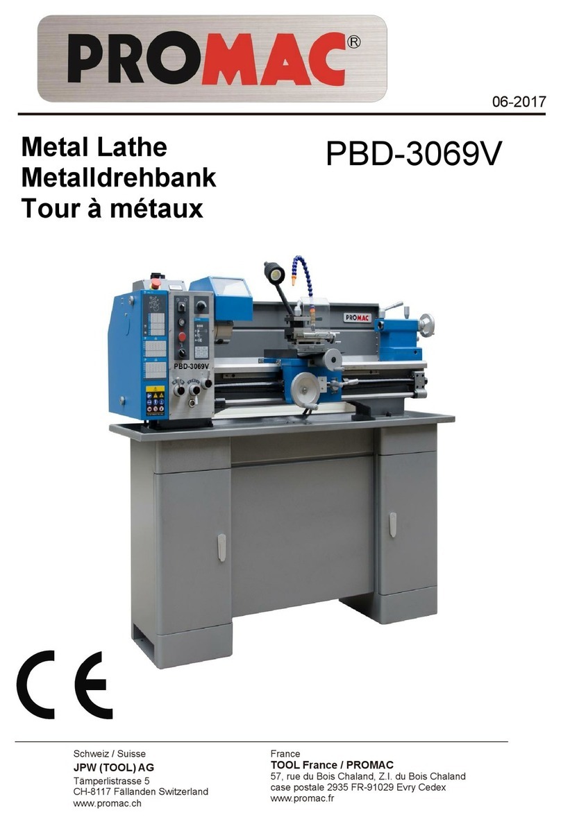
Promac PBD-1830V User manual

Metal Lathe
Metalldrehbank
Tour à métaux
06-2017
PBD-1830V
Schweiz / Suisse
JPW (TOOL) AG
Tämperlistrasse 5
CH-8117 Fällanden Switzerland
www.promac.ch
France
TOOL France / PROMAC
57, rue du Bois Chaland, Z.I. du Bois Chaland
case postale 2935 FR-91029 Evry Cedex
www.promac.fr

CE‐ConformityDeclaration
CE‐Konformitätserklärung
DéclarationdeConformitéCE
Product/Produkt/Produit:
Metallathe/Metalldrehbank/Touràmétaux
PBD‐1830V
Brand/Marke/Marque:
PROMAC
Manufacturer/Hersteller/Fabricant:
JPW(Tool)AG,Tämperlistrasse5,CH‐8117Fällanden
Schweiz/Suisse/Switzerland
Weherebydeclarethatthisproductcomplieswiththeregulations
Wirerklärenhiermit,dassdiesesProduktderfolgendenRichtlinieentspricht
Parlaprésente,nousdéclaronsqueceproduitcorrespondauxdirectivessuivantes
2006/42/EC
MachineryDirective
Maschinenrichtlinie
DirectiveMachines
2014/30/EU
electromagneticcompatibility
elektromagnetischeVerträglichkeit
compatibilitéélectromagnétique
designedinconsiderationofthestandards
undentsprechendfolgenderzusätzlicherNormenentwickeltwurde
etétédéveloppédanslerespectdesnormescomplémentairessuivantes
ENISO12100:2010
ENISO23125:2015
EN60204‐1:2006/AC2010
EN61000‐6‐2:2005
EN61000‐6‐4:2007/A1:2011
ResponsiblefortheDocumentation/Dokumentations‐Verantwortung/ResponsabilitédeDocumentation:
HansjörgMeier
HeadProduct‐Mgmt./LeiterProdukt‐Mgmt./Resp.GestiondesProduits
JPW(Tool)AG
2017‐03‐06AlainSchmid,GeneralManager
JPW(Tool)AG,Tämperlistrasse5,CH‐8117Fällanden
Schweiz/Suisse/Switzerland

3
ENOperatingInstructions(Original)
1.0AboutthisManual
ThismanualisprovidedbyPROMAC,coveringthesafeoperationandmaintenanceproceduresforaPROMACModelPBD‐
1830V Metal Lathe. This manual contains instructions on installation, safety precautions, general operating procedures,
maintenanceinstructionsandpartsbreakdown.Themachinehasbeendesignedandconstructedtoprovideconsistent,long‐
termoperationifusedinaccordancewiththeinstructionsassetforthinthisdocument.
Retainthismanualforfuturereference.Ifthemachinetransfersownership,themanualshouldaccompanyit.
2.0TableofContents
Section Page
1.0 Aboutthismanual...........................................................................................................................................3
2.0 Tableofcontents.............................................................................................................................................3
3.0 Importantsafetyinstructions......................................................................................................................4~6
3.1 Designateduseandlimitationstouse....................................................................................................6
3.2 Remaininghazards..................................................................................................................................6
4.0 Specifications...............................................................................................................................................7~8
5.0 Machinedescription........................................................................................................................................9
6.0 Setupandassembly.......................................................................................................................................10
6.1 Unpackingandcleanup........................................................................................................................10
6.2 Shippingcontents..................................................................................................................................10
6.3 Assembly...............................................................................................................................................10
6.4 Initiallubrication...................................................................................................................................10
6.5 Installation.............................................................................................................................................10
7.0 Electricalconnections..............................................................................................................................10~11
7.1 Groundinginstructions..........................................................................................................................10
7.2 Extensioncords.....................................................................................................................................11
8.0 Adjustments.............................................................................................................................................11~13
8.1 Spindlespeedrangeselection...............................................................................................................11
8.2 Changegearsetup.................................................................................................................................11
8.3 Taperturningwithtailstock..................................................................................................................12
8.4 Taperturningwithtopslide..................................................................................................................12
8.5 Threejawuniversalchuck.....................................................................................................................12
8.6 Fourjawindependentchuck.................................................................................................................13
8.7 Livecentre.............................................................................................................................................13
8.8 Steadyrestandfollowrest...................................................................................................................13
9.0 Operatingcontrols.........................................................................................................................................14
10.0 Machineoperation..................................................................................................................................14~16
10.1 Cuttingexecution..................................................................................................................................14
10.2 Chucking................................................................................................................................................14
10.3 CuttingToolSetup.................................................................................................................................15
10.4 Recommendedspindlespeeds.............................................................................................................15
10.5 Manualturning......................................................................................................................................15
10.6 Turningwithautofeed..........................................................................................................................15
10.7 Threadcutting.......................................................................................................................................16
10.8 Drillingoperation..................................................................................................................................16
11.0 Usermaintenance..........................................................................................................................................16
11.1Lubrication.............................................................................................................................................16
12.0 Troubleshooting............................................................................................................................................17
13.0 Environmentalprotection.............................................................................................................................17
14.0 Availableaccessories.....................................................................................................................................17
15.0 Replacementparts...................................................................................................................................18~27
16.0 Wiringdiagrams.......................................................................................................................................28~29

3.0IMPORTANTSAFETY
INSTRUCTIONS
READALLINSTRUCTIONSBEFOREUSINGTHISLATHE.
–Toreduceriskofinjury:
1. Read and understand entire owner’s manual before
attemptingassemblyoroperationofthismachine.
2. Read and understand the warnings posted on the
machineandinthismanual.
3. Replace warning labels if they become obscured or
removed.
4. Thismachineisdesignedandintendedforusebyproperly
trained and experienced personnel only. If you are not
familiarwiththeproperandsafeoperationofametal
lathe, do not use until proper training and knowledge
havebeenobtained.
5. Donotusethismachineforotherthanitsintendeduse.If
usedforotherpurposes,JETdisclaimsanyrealorimplied
warranty and holds itself harmless from any injury that
mayresultfromthatuse.
6. Alwayswearapprovedsafetyglassesorfaceshieldwhile
usingthismachine.(Everydayeyeglassesonlyhaveimpact
resistantlenses;theyarenotsafetyglasses.)
7. Beforeoperatingthismachine,removetie,rings,watches
andotherjewellery, and roll sleevesuppastthe elbows.
Remove loose clothing and confine long hair. Non‐slip
footwear or anti‐skid floor strips are recommended. Do
notweargloves.
8. Wearhearingprotection(plugsormuffs)duringextended
periodsofoperation.
9. Some dust created by sawing may contain chemicals
knowntocausecancer,birthdefectsorother
reproductive harm. Some examples of these chemicals
are:
Leadfromleadbasedpaint.
Crystalline silica from bricks, cement and other
masonryproducts.
Arsenic and chromium from chemically treated
lumber.
Yourriskofexposurevaries,dependingonhowoftenyou
dothistypeofwork.Toreduceyourexposuretothese
chemicals, work in a well‐ventilated area and work with
approved safety equipment, such as face or dust masks
that are specifically designed to filter out microscopic
particles.
10. Do not operate this machine while tired or under the
influenceofdrugs,alcoholoranymedication.
11. MakecertaintheswitchisintheOFF position before
connectingthemachinetothepowersupply.Turnoffall
controlsbeforeunplugging.
12. Makecertainthemachineisproperlygrounded.Connect
to a properly grounded outlet only. See Grounding
instructions.
13. Make all machine adjustments or maintenance with the
machineunpluggedfromthepowersource.
14. Removeadjustingkeysandwrenches.Formahabitof
checking to see that keys and adjusting wrenches are
removedfromthemachinebeforeturningiton.
15. Keepsafetyguardsinplaceatalltimeswhenthemachine
is in use. If removed for maintenance purposes, use
extremecautionandreplacetheguardsimmediatelyafter
maintenanceiscomplete.
16. Checkdamagedparts.Beforefurtheruseofthemachine,
aguardorotherpartthatisdamagedshouldbecarefully
checked to determine that it will operate properly and
perform its intended function. Check for alignment of
movingparts,bindingofmovingparts,breakageofparts,
mounting and any other conditions that may affect its
operation.A guard orother partthat is damaged should
beproperlyrepairedorreplaced.
17. Provide for adequate space surrounding work area and
non‐glare,overheadlighting.
18. Keeptheflooraroundthemachinecleanandfreeofscrap
material,oilandgrease.
19. Keep visitors a safe distance from the work area. Keep
childrenaway.
20. Make your workshop child proof with padlocks, master
switchesorbyremovingstarterkeys.
21. Give your work undivided attention. Looking around,
carrying on a conversation and “horse‐play” are careless
actsthatcanresultinseriousinjury.
22. Keep an ergonomic body position. Maintain a balanced
stanceatalltimessothatyoudonotfallorleanagainst
thechuckorothermovingparts.Donotoverreachoruse
excessiveforcetoperformanymachineoperation.
23. Usetherighttoolatthecorrectspeedandfeedrate.Do
notforceatoolorattachmenttodoajobforwhichitwas
not designed. The right tool will do the job better and
safer.
24. Themachineisintendedforindooruse.Toreducetherisk
ofelectricshock,donotuseoutdoorsoronwetsurfaces.
25. Donothandleplugormachinewithwethands.
26. Userecommendedaccessories;improperaccessoriesmay
behazardous.
27. Maintain tools with care. Keep tools sharp and clean for
the best and safest performance. Follow instructions for
lubricatingandchangingaccessories.
28. Turn off machine and disconnect from power before
cleaning.Useabrush or compressedairtoremovechips
ordebris;donotusebarehands.
29. Donotstandonthemachine.Seriousinjurycouldoccurif
themachinetipsover.
30. Never leave the machine running unattended. Turn the
poweroffanddonotleavethemachineuntilitcomesto
acompletestop.
31. Remove loose items and unnecessary work pieces from
theareabeforestartingthemachine.
32. Pullthemainsplugifthemachineisnotinuse.
33. Makesuretheworkpieceissecurelyclamped.
5
Familiarizeyourselfwiththefollowingsafetynoticesusedinthismanual:
WARNING:Thismeansthatifprecautionsarenotheeded,itmayresultinserious,orpossiblyevenfatal,injury.
CAUTION:Thismeansthatifprecautionsarenotheeded,itmayresultinminorinjuryand/orpossiblemachine
damage.
SAVETHESEINSTRUCTIONS
WARNING:
Thesesymbolsblowadvisethatyoufollowthecorrectsafetyprocedureswhenusingthismachine.
Readandunderstandtheentireuser
manualbeforeattemptingassemblyor
machineoperation.
Alwayswearapprovedworkingoutfit
Wearsafetygoggles.
Wearearprotection.
Alwaysweartheapprovedworkingoutfit
Wearsafetyshoes.
Removetie,rings,watches,jewellery.
Rollupsleevesaboveelbows.
Removealllooseclothingandconfine
longhair
Makeallmachineadjustmentsor
maintenancewiththemachineunplugged
fromthepowersource.
Anyworkpiecestockextendingtherear
endoftheheadstockmustbecovered
onitsentirelength.Highdangerofinjury
Donotoperatethismachineunderthe
influenceofdrugs,alcoholormedication
Donotweargloveswhileoperatingthis
machine
Connectionandrepairworkonthe
electricalinstallationmaybecarriedoutby
aqualifiedelectricianonly.
Neverreachintothemachinewhileitis
operatingorrunningdown.

6
3.1Designateduseandlimitationstouse
Themachineisdesignedforturninganddrillingmachinablemetalandplasticmaterialsonly.
Theworkpiecemustallowtosafelybeloaded,supportedandclamped.
Themachineisintendedforindooruse.TheprotectionratingoftheelectricalinstallationisIP54.
Toavoidtipping,themachinemustbebolteddownwithtwoanchorbolts.
Ifusedforotherpurposes,PROMACdisclaimsanyrealorimpliedwarrantyandholdsitselfharmlessfromanyinjurythatmayresult
fromthatuse.
WARNING:
Themachineisnotsuitableformachiningmagnesium…highdangertofire!
Neverplaceyourfingersinapositionwheretheycouldcontactanyrotatingpartsorchips.
Checkthesaveclampingoftheworkpiecebeforestartingthemachine.
Don’texceedtheclampingrangeofthechuck.
Workpieceslongerthan3timesthechuckingdiameterneedtobesupportedbythetailstockorasteadyrest.
Avoidsmallchuckingdiametersatbigturningdiameters.Avoidshortchuckinglengthsandsmallchuckingcontact.
Donotexceedthemaxspeedoftheworkholdingdevice.
Usetherighttoolatthecorrectspeedandfeedrate.Donotforceatoolorattachmenttodoajobforwhichitwasnotdesigned.The
righttoolwilldothejobbetterandmoresafely.
Userecommendedaccessories;improperaccessoriesmaybehazardous.
Maintaintoolswithcare.Keepcuttingtoolssharpandcleanforthebestandsafestperformance.
Followinstructionsforlubricatingandchangingaccessories.
Donotattempttoadjustorremovetoolsduringoperation.
Neverstoparotatingchuckorworkpiecewithyourhands.
Chooseasmallspindlespeedwhenworkingunbalancedworkpiecesandforthreadingandtappingoperations.
Anyworkpiecestockextendingtherearendoftheheadstockmustbecoveredonitsentirelength.Highdangerofinjury!
Longworkpiecesmayneedasteadyrestsupport.Alongandthinworkpiececansuddenlybendathighspeedrotation.
Nevermovethetailstockortailstockquillwhilethemachineisrunning.
Removecuttingchipswiththeaidofanappropriatechiphookwhenthemachineisatastandstillonly.
Measurementsandadjustmentsmaybecarriedoutwhenthemachineisatastandstillonly.
Maintenanceandrepairworkmayonlybecarriedoutafterthemachineisprotectedagainstaccidentalstarting,pullthemainsplug.
Removelooseitemsandunnecessaryworkpiecesfromtheareabeforestartingthemachine.
Rotateworkpiecebyhandbeforeapplyingpower.Uselowestspeedwhenstartingnewworkpiece.
Tightenalllocksbeforeoperating.
3.2Remaininghazards
Whenusingthemachineaccordingtoregulationssomeremaininghazardsmaystillexist.
Therotatingworkpieceandchuckcancauseinjury.
Thrownandhotworkpiecesandcuttingchipscanleadtoinjury.
Chipsandnoisecanbehealthhazards.Besuretowearpersonalprotectiongearsuchassafetygogglesandearprotection.
Theuseofincorrectmainssupplyoradamagedpowercordcanleadtoinjuriescausedbyelectricity.
Whenopeningtheelectricalcabinet,thegrid‐feedingvoltagepersists.Thereforepayattentioneverytimeyouenterit.

7
4.0Specifications
Modelnumber............................................................................................................................................................................PBD‐1830V
Stocknumber…………………………………………………………………….......................................................................................................PBD‐1830V
Motorandelectricals:
Motortype……………………………………………………................................................................................................DC‐motor,variablespeed
Motorpower.................................................................................................................................................................................0.6kW
Powersupply................................................................................................................................................................1~230V,PE,50Hz
Protectionclass.................................................................................................................................................................................IP54
Listedloadamps...............................................................................................................................................................................2.2A
Capacities:
Centreheight.................................................................................................................................................................................90mm
Swingoverbed............................................................................................................................................................................180mm
Swingovercrossslide..................................................................................................................................................................110mm
DistancebetweenCentres...........................................................................................................................................................300mm
Spindle:
Spindlenosemounting.............................................................................................cylindricalmount(Ø100mm,Ø72mm,Ø84x3xØ9)
Spindlebore...................................................................................................................................................................................21mm
Spindletaper.....................................................................................................................................................................................MT3
Numberofspindlespeeds...........................................................................................................................................................variable
Rangeofspindlespeeds...............................................................................................................................50~1250&100~2500/min
Tailstock:
Tailstockramtravel.......................................................................................................................................................................50mm
Tailstocktaper...................................................................................................................................................................................MT2
ToolSlide:
Crossslidetravel............................................................................................................................................................................85mm
Topslidetravel..............................................................................................................................................................................75mm
Toolsizemax...........................................................................................................................................................................10x10mm
Leadscrewpitch..............................................................................................................................................................................2mm
Longitudinalfeed...................................................................................................................................................(2x)0,1&0.2mm/rev
Metricthreads....................................................................................................................................................(14x)0.25~3.0mm/rev
Inchthreads.....................................................................................................................................................................(12x)8~44TPI
Materials:
Headstock,tailstock,slides.........................................................................................................................................................Castiron
Spindlebearings...........................................................................................................................Taperrollerbearings,qualitylevelP5
Soundemissioninidle1.....................................................................................................................................................73.4dB(LpA)
Soundemissionduringcutting1........................................................................................................................................78.3dB(LpA)
1Soundemissionmeasuredin1mdistance,1.6maboveground.Thespecifiedvaluesareemissionlevelsandarenotnecessarilytobe
seenassafeoperatinglevels.Asworkplaceconditionsvary,thisinformationisintendedtoallowtheusertomakeabetterestimation
ofthehazardsandrisksinvolvedonly.
DimensionsandWeights:
Overalldimensions,assembled(WxDxH)...............................................................................................................800x460x40mm
Shippingdimensions(WxDxH).............................................................................................................................820x480x510mm
Netweight(approximate)...............................................................................................................................................................65kg
Shippingweight(approximate).......................................................................................................................................................75kg
L=length;W=width;H=height;D=depth
Thespecificationsinthismanualwerecurrentattimeofpublication,butbecauseofourpolicyofcontinuousimprovement,JETreserves
therighttochangespecificationsatanytimeandwithoutpriornotice,withoutincurringobligations.

8
4.1Spindlenosemounting:
Figure4‐1:Spindlenosemounting
4.2Anchorboltholepattern:
Figure4‐2:LatheBedanchorboltpattern
WARNING:
Toavoidtipping,themachinemustbebolteddownwithtwoanchorbolts(notprovided).

9
5.0MachineDescription
Figure5‐1:Machinedescription
A.............................................Changegearquadrant
B..............................................................Pulleycover
C................................................................Headstock
D...........................................Chuckandchuckguard
E...................................Toolpostandtoolpostguard
F....................................................................Topslide
G...........................................................CarriageLock
H...................................................................Tailstock
I.............................................................Splashguard
J..................................................................Lathebed
K................................................................Leadscrew
L...................................................................Chiptray
M.....................................................................Apron
Figure5‐2:Machinedescription
N.............................................SpindlepowerON/OFF
O..........................................Spindleforward/reverse
P......................................Variablespeedselectknob
Q........................................................EmergencyStop
R................................................Spindlespeeddisplay
S....................................................Apronhandwheel
T.............................................Crossslidehandwheel
U...............................................Topslidehandwheel
V...........................................................Half‐nutlever
W.....................................Topslidetaperadjustment
Figure5‐3Machinedescription

10
6.0SetupandAssembly
WARNING:
Readandunderstandtheentirecontentsofthismanual
beforeattemptingassemblyoroperation.Failuretocomply
maycauseseriousinjury.
6.1Unpackingandcleanup
Removeallcontentsfromshippingcrateandcomparepartsto
thecontentslistinthismanual.Ifshippingdamageoranypart
shortages are identified, contact your distributor. Do not
discardcrateorpackingmaterialuntildrillpressisassembled
andrunningsatisfactorily.
Cleanallrustprotectedsurfaceswithkeroseneoralight
solvent.Donotuselacquerthinner,paintthinnerorgasoline,
asthesecandamageplasticcomponentsandpaintedsurfaces.
6.2Shippingcontents
1 Machine
1 Cabinetstand
1 Coolantfacility
1 Machinelamp
1 100mm3‐jawuniversalchuck
1 100mm4‐jawindependentchuck
1 Chuckguard
1 4‐waytoolpost
1 Toolpostguard
1 Setofchangegears
1 MT3fixedcentre
1 MT2fixedcentre
1 Steadyrest
1 Followrest
1 Operatingtoolsintoolbox
1 Oilcan
1 Operatinginstructionsandpartsmanual
6.3Assembly
Themachinecomescompletelyassembled.
Installthedrivebelt(V‐belt).
Inspectthatallfastenersaretight.
6.4Initiallubrication
Themachinemustbeservicedatalllubricationpointsbeforeitis
placedintoservice(seechapter11.1forlubrication).
6.5Installation
Unboltthelathefromtheshippingcratebottom.
Useheavydutyfibrebeltforliftingthemachineoffthepallet.
Warning:
Themachineisheavy(75kg)!
Assurethesufficientloadcapacityandproperconditionofyour
liftingdevices.
Neverstepunderneathsuspendedloads.
Toavoidtipping,themachinemustbebolteddownwithtwo
anchorbolts(notprovided).
Toavoidtwistingthebed,makesurethesetupsurfaceis
absolutelyflatandlevel.
Loosenanchorbolts,shimandtightenboltsifneeded.
Themachinemustbeleveltobeaccurate!
7.0ElectricalConnections
WARNING:
Allelectricalconnectionsmustbedonebyaqualified
electricianincompliancewithalllocalcodesandordinances.
Failuretocomplymayresultinseriousinjury.
The PBD‐1830V Metal Lathes are rated at 1~230V, PE, 50Hz
power supply. The machines come with a plug designed for
useonacircuitwithagroundedoutlet.
Mainsconnectionandanyextensioncordsandplugsused
mustcomplywiththeinformationonthemachinelicense
plate.
Themainsconnectionmusthavea16Asurge‐prooffuse.
OnlyuseextensioncordsmarkedH07RN‐F,withwires1,5mm2
ormore.
Thetotallengthofcordmaynotexceed18Meter
Powercordsandplugsmustbefreefromdefects.
Connectionsandrepairstotheelectricalequipmentmayonly
becarriedoutbyqualifiedelectricians.
Themachineisequippedwith1.8mpowercordandplug.
Beforeconnectingtopowersource,besuremainswitchisin
offposition.
7.1Groundinginstructions
Thistoolmust be grounded.In the event ofamalfunction or
breakdown, grounding provides a path of least resistance for
electriccurrenttoreducetheriskofelectricshock.Thistoolis
equipped with an electric cord having an equipment‐
groundingconductorandagroundingplug.Theplugmustbe
inserted into an appropriate outlet that is properly installed
and grounded in accordance with all local codes and
ordinances.
WARNING:
Improperconnectionoftheequipment‐groundingconductor
canresultinariskofelectricshock.Checkwithaqualified
electricianorservicepersonifyouareindoubtastowhether

11
theoutletisproperlygrounded.Donotmodifytheplug
providedwiththetool.
The green/yellow conductor is the equipment‐grounding
conductor.Ifrepairorreplacementoftheelectriccordorplug
is necessary, do not connect the equipment‐grounding
conductortoaliveterminal.
Useonly3‐wireextensioncordswithgroundingplugs.
Repairorreplacedamagedorworncordimmediately.
7.2Extensioncords
Theuseofextensioncordsisdiscouraged;trytoposition
machines near the power source. If an extension cord is
necessary,makesureitisingoodcondition.
Anundersizedcordwillcauseadropinlinevoltageresultingin
lossofpowerandoverheating.
OnlyuseextensioncordsmarkedH07RN‐F,withwires1,5mm2
ormore.
Thetotallengthofcordmaynotexceed18Meter
Extensioncordsandplugsmustbefreefromdefects.
8.0Adjustments
8.1Changingspindlespeedrange
Thespeedsofthelathearecontrolledbythevariablespeed
selectknob(W, Fig5‐2)aswellastheposition of thebelton
thepulleys(Fig8‐1).
Figure8‐1:Spindlespeedrangesetup
A.........50~1250RPM..........formaximumtorque.
B..........100~2500RPM........formaximumspeed.
Removethepulleycover(C,Fig5‐1)tochangethebelt
position.
8.2Changegearsetup
Removethepulleycover.
Therotationalspeedoftheleadscrew,andhencetherateof
feedofthecuttingtool,isdeterminedbythegear
configurationandbythefeedspeedselectlever(R,Fig5‐2).
Assemblethegearswithdesiredsetup(Fig8‐2)
Figure8‐2:Changegearsetup
Adjustgearstomeshwithupperandlowergear.
Placing ordinary paper in between gears helps to adjust for
correctgearspacing(…removethepaperafterwards!).
Reinstallthepulleycover.

12
8.3Taperturningwithtailstock
Mounttheworkpiecefittedwiththedrivedogbetween
centres.Thedrivedogisdrivenbythefaceplate.
Lubricatethetailstockcentrewithgreaseto prevent tip from
overheating.
Figure8‐3:Taperturningbetweencentres
Toturnataper,offsetthetailstock,loosenthelockingscrews
(Z,Fig8‐3)andusescrews(Y)toadjust.
After taper turning, the tailstock must be returned to its
originalposition.Turnatestpieceandadjustuntilthemachine
turnsaperfectcylinder.
8.4Taperturningwithtopslide
Byanglingthetopslide,tapersmaybeturned.
Loosenhexsocketboltswith4mmallenwrench(W,Fig8‐4)
androtatethetopslideaccordingtothegraduatedscale.
Figure8‐4:Taperturningwithtopslide
8.5Threejawuniversalchuck
Withthisuniversalchuck,cylindrical,triangularandhexagonal
stockmaybeclamped(Fig8‐5).
Figure8‐5:Threejawuniversalchuck
Toholdbigdiameterstock,asetofODchuckjawsissupplied.
Thejawsneedtobeinsertedtothechuckinthecorrectorder.
UseMolykotePasteG(oradequategrease)tolubricatethe
jaws.
8.6Fourjawindependentchuck(Optional)
This chuck has four independently adjustable chuck jaws (Fig
8‐6).
These permit the holding of square and asymmetrical pieces
andenablesaccurateconcentricset‐upofcylindricalpieces.
Figure8‐6:Fourjawindependentchuck

13
8.7Livecentre(Optional)
Thelivecentre(Fig8‐7)ismountedinballbearings.
Itsuseishighlyrecommendedforspeedsabove500RPM.
Figure8‐7:Livecentre
Toejectthelivecentre,fullyretractthetailstockquill.
8.8Steadyrestandfollowrest
The rests prevent flexing of long and thin work pieces under
pressurefromthetool.
Thesteadyrest(Fig8‐8)servesasa support forlongershafts
andensuresasafeandchatterfreeoperation.
Figure8‐8:Steadyrest
The follow rest (Fig 8‐9) is mounted on the carriage and
followsthemovementofthetool.
Figure8‐9:Followrest
Setthefingers(2)snugbutnotoverlytight.
Lubricatethefingerstopreventprematurewear.

14
9.0OperatingControls
RefertoFigure9‐1:
N...........................................SpindlepowerON/OFF
O..........................................Spindleforward/reverse
P......................................Variablespeedselectknob
Q......................................................EmergencyStop
R................................................Spindlespeeddisplay
Figure9‐1:OperatingControls
10.0MachineOperation
10.1Cuttingexecution
Beforestartingthemachinechecktheproperchucking.
Close the chuck guard and pulley cover before you start the
machine.
Selectrunningdirection,forwardorreverse(O,Fig9‐1).
YoucanstartthemachinewiththegreenON‐button(N).
TheredOFF‐buttonstopsthemachine.
Thespeedcanbeadjustedwiththevariablespeedselectknob
(P).
Thespindlespeedwillbeshownonthedisplay(R).
Theemergencystopbutton(Q)stopsallmachinefunctions.
Turnemergencystopbuttonclockwisetoreset.
Unplugthemachineifnotinuse!
10.2Chucking
Donotexceedthemaxspeedoftheworkholdingdevice.
Jawteethandscrollmustalwaysbefullyengaged.Otherwise
chuckjawsmaybreakandflyoffinrotation(Fig10‐1).
Figure10‐1:Poorjawengagements
Avoidlongworkpieceextensions.Partsmaybend(Fig10‐2)or
flyoff(Fig10‐3).Usetailstockorresttosupport.
Figure10‐2:Workpiecetoolong
Figure10‐3:Workpiecetoolong
Avoid short clamping contact (A, Fig 10‐4) or clamping on a
minordiameter(B).Facelocateworkpieceforaddedsupport
Figure10‐4:Poorclamping

15
10.3CuttingToolSetup
The cutting angle is correct when the cutting edge is in line
with the centre axis of the work piece. Use the point of the
tailstockcentreasagaugeandshimsunderthetooltoobtain
thecorrectcentreheight(Fig10‐5).
Figure10‐5:Cuttingtoolsetup
Useaminimumoftwoscrewstoclampthecuttingtool.
Avoidlargetoolextensions.
10.4Recommendedspindlespeeds
ATTENTION:
Generallyspeaking,thesmallerthecutdiameter,thegreaterthe
RPMrequired.Softmaterialsrequirehigherspeeds;hardmetals
slowerspeeds.
Metalisusuallymachinedatslowerspeedsandcuttingoilis
applied.
Recommended speeds for cutting 10mm diameter, with HSS
tools(Highspeedsteeltools):
Plastic:..........................................................2500RPM
Aluminium:....................................................2500RPM
Brass:............................................................1000RPM
Castiron:.......................................................1000RPM
Mildsteel:........................................................800RPM
Highcarbonsteel:...........................................600RPM
Stainlesssteel:.................................................300RPM
Forcarbidetools(HM),5timeshigherspeedscanbechosen.
Forexample:
Turningmildsteelatadiameterof20mmallows
WithHSStool...................................................400RPM
Withcarbidetool...........................................2000RPM
10.5Manualturning
Aprontravel(S,Fig10‐6),crosstravel(T)andtopslidetravel
(U)canbeoperatedforlongitudinalandcrossfeeding.
Figure10‐6:Machinecontrols
Thecorrectfeeddependsonthematerialtobecut,thecutting
operation,thetypeoftool,therigidityoftheworkpiece
chucking,thedepthofcutandthedesiredsurfacequality.
Whenroughingbigdiametersreducethedepthofcut!
10.6Turningwithautofeed
Movethehalf‐nutlever(V,Fig10‐6)down,toengagethe
automaticlongitudinalfeed.Moveituptodisengage
Forexample:
Operation feedrate
Stockremoval..............................................0,2mm/rev
Finishingcut.................................................0 . 1 m m / r e v
NOTE:Twofeedratesareavailablewithdifferentchangegear
setup(Fig10‐7).
Figure10‐7:Availablefeedrates

16
10.7Threadcutting
Threading is performed in multiple passes with a threading
tool.
Eachdepthofcutshouldbeabout0,2mmandbecomelessfor
thefinishingpasses.
A)Tocutinchandmetricthreads
Set the machine up for the desired threading pitch (see
chapter8.2).
Selectthelowestpossiblespindlespeed.
Engagethehalvenut(V,Fig10‐6).
NOTE:Thehalvenutmuststayengagedduringtheentire
threadingprocess.
‐Setthetoolupforthethreadingpass.
‐Startthemotor.
‐Whenthetoolapproachestheendofcut,stopthemotorand
atthesametimebackthetoolout,sothatitclearsthethread
diameter.
‐Startthemotorinreversedirection,letthecuttingtooltravel
backtothestartingpoint.
Repeatthesestepsuntilyouhaveobtainedthedesiredresults.
B)Tocutmetricthreadswithpitch
0,25/0,4/0,5/1,0/2,0mm:
Thehalvenutcanbeopenedattheendofcut,ratherthanthe
motorbeingstoppedandreversed.
10.8Drillingoperation
UseadrillchuckwithMT2arbor(option)toclampcentredrills
andtwisteddrillsinthetailstock(Fig10‐8).
Figure10‐8:Drillingoperation
Forrecommendedspeedsrefertosection10.4
Toejectthedrillchuck,fullyretractthetailstockquill.
11.0User‐Maintenance
WARNING:
Beforeanyinterventiononthemachine,disconnectitfrom
electricalsupply,pullthemainsplug.Failuretocomplymay
causeseriousinjury.
Animportantsecurityfactoristhecleaningofthemachine,of
bed,carriageandslides,ofthefloorandthesurrounding
places.
Looseobjectscouldcomeintocontactwiththemovingchuck
orworkpiece,creatinghazards.
Emptythechiptrayregularly.
Replacethecoolantregularly,followmanufacturer’sadvice.
Checkthatboltsaretightandelectricalcordsareingood
condition.Ifanelectricalcordisworn,cut,ordamagedinany
way,haveitreplacedimmediately.
Motorbrushes:
Themotor brushesaredueto wear andneed tobereplaced
whenshorterthan12mm.
Setofbrushes:ArticleNo.PBD1830V‐103B
11.1Lubrication
Spindlebearingsarepre‐lubricatedandsealed,andrequireno
furtherlubrication.
Weeklyapplyoil:
DIN51502CGISOVG68
(e.g.BPMaccurat68,CastrolMagnaBD68,MobilVectra2)
1…oilballsonchangegearhubs
2…oilbedwayslightly
3…oiltailstockquilloverentirelength
4…oilleadscrewonentirelength
5…oilballonleadscrewbracket
6…oilballsontopslide
7…oilballsontailstock
8...oilballsoncarriage
9...oilballsonapron
Monthlyapplygrease:
DIN51807‐1nonslinginggrease
(e.g.BPL2,MobilgreaseSpecial).
10…greaseteethofchangegears
11…greaserackoverentirelength

17
12.0Troubleshooting
Symptom PossibleCause Correction*
Lathewillnotstart.
Latheunpluggedfromwall,ormotor. Checkallplugconnections.
Fuseblown,orcircuitbreakertripped. Replacefuse,orresetcircuitbreaker.
Corddamaged. Replacecord.
Chuckguardnotclosed. Closechuckguard.
Pulleycoverremoved Installpulleycover
Lathedoesnotcomeupto
speed.
Extensioncordtoolightortoolong. Replacewithadequatesizeandlengthcord.
Lowcurrent. Contactaqualifiedelectrician.
Lathevibratesexcessively.
Baseonunevensurface. Locatelatheonevenfloor.
Lathenotboltedtothefloor Boltmachinetothefloor
Unbalancedworkpiece Reducespeed
Workpiecedeflection Improvechuckinglengthordiameter,support
ontailstockend
Tooldeflection Reducetoollength
Slidebacklash Adjustslides
Slidesrunningdry Lubricatewithoil
Dulltooltip Re‐sharpenorchangetool
Chiploadtoohigh Reducedepthofcutorfeed
Noisyoperation Drychangegearhubs. Lubricatewithoil.
Drychangegears Lubricatewithgrease.
Tooltipburns
Cuttingspeedtoohigh Reducespindlespeed
Dulltooltip. Re‐sharpenorchangetool
Drycutting. Usecoolant.
Feedingtooslowly. Increasefeedrate.
Machineturnsataper.
Tailstockalignmentisoffset. Aligntailstockposition.
Machinebedistwisted. Standsupportingsurfacemustbeflat.Shimif
needed
Workpiecedeflection. Reducedepthofcutorfeed
Drillchuckorarbordoesnot
stayinplace.
Dirt,grease,etc.onarbor,chuck,or
tailstockquill
Cleanallmatingsurfacesthoroughlywitha
cleaner‐degreaser.
*WARNING:Somecorrectionsmayrequireaqualifiedelectrician.
Table1
13.0EnvironmentalProtection
Protecttheenvironment.
Disposeallpackagingmaterialinanenvironmentalfriendlymanner.
Disposecoolantinanenvironmentallyfriendlymanner.
Yourappliancecontainsvaluablematerialswhichcanberecoveredorrecycled.Pleaseleaveitataspecializedinstitution.
14.0AvailableAccessories
RefertotheJETpricelist.

18
15.0ReplacementParts
PBD‐1830VAssemblyBreakdown‐1

19
PBD‐1830VPartsListforBreakdown‐1
Index Part
No. No. Description Size Qty.
101‐‐‐‐‐‐PBD1830V‐1...........................HEXAGONSOCKETHEADCAPSCREWDIN912.......M5×25.........................4
102‐‐‐‐‐‐PBD1830V‐2...........................SPLITWASHERDIN127...........................................5................................4
103‐‐‐‐‐‐PBD1830V‐103.......................D.C.MOTOR.................................................................................................1
‐‐‐‐‐‐‐‐‐‐‐PBD1830V‐103B.....................BrushforD.CMOTOR(notshown).............................................................2
104‐‐‐‐‐‐PBD1830V‐104.......................V‐BELTPULLEYENGINE...............................................................................1
105‐‐‐‐‐‐PBD1830V‐3...........................FEATHERKEY......................................................DIN6885‐A4×4×20.....1
106‐‐‐‐‐‐PBD1830V‐4...........................SETSCREWDIN915................................................M6×8.......................1
107‐‐‐‐‐‐PBD1830V‐107.......................SYNCHRONOUSBELT..............................................Gates5M‐365...........2
108‐‐‐‐‐‐PBD1830V‐108.......................SUPPORTINGPLATE.....................................................................................1
109‐‐‐‐‐‐PBD1830V‐5...........................DISK........................................................................8................................3
110‐‐‐‐‐‐PBD1830V‐6...........................HEXAGONSOCKETHEADCAPSCREWDIN912.......M8×20.......................3
111‐‐‐‐‐‐PBD1830V‐111.......................SLIDINGPAD................................................................................................1
112‐‐‐‐‐‐PBD1830V‐7...........................HEXAGONSOCKETHEADCAPSCREWDIN912.......M6×30.........................1
113‐‐‐‐‐‐PBD1830V‐113.......................THRUSTBEARING.........................................................................................1
114‐‐‐‐‐‐PBD1830V‐8...........................HEXAGONSOCKETHEADCAPSCREWDIN912.......M6×20.........................2
115‐‐‐‐‐‐PBD1830V‐115.......................AXIS..............................................................................................................1
116‐‐‐‐‐‐PBD1830V‐116.......................BEARINGBLOCK‐INTER‐MEDIATEWHEEL....................................................1
116‐1‐‐PBD1830V‐9...........................ALIGNMENTPIN......................................................4×22.............................1
117‐‐‐‐‐‐PBD1830V‐10.........................DISK.........................................................................8...................................1
118‐‐‐‐‐‐PBD1830V‐11.........................HEXAGONNUT........................................................M8................................3
119‐‐‐‐‐‐PBD1830V‐12.........................LOCKINGRING.........................................................DIN471‐8×0.8.............1
120‐‐‐‐‐‐PBD1830V‐120.......................COUNTERSHAFT...........................................................................................1
121‐‐‐‐‐‐PBD1830V‐121.......................DEEPGROOVEBALLBEARING.................................608‐RZ..........................2
122‐‐‐‐‐‐PBD1830V‐122.......................PULLEYCOUNTERSHAFT..............................................................................1
123‐‐‐‐‐‐PBD1830V‐13.........................LOCKINGRING.........................................................DIN471‐22×1..............1
124‐‐‐‐‐‐PBD1830V‐124.......................BOTTOMCOVER...........................................................................................1
125‐‐‐‐‐‐PBD1830V‐14.........................HEXAGONSOCKETHEADCAPSCREWDIN912.......M8×25.........................4
126.......PBD1830V‐15.........................DISK.........................................................................8...................................4
127.......PBD1830V‐16.........................NUT.........................................................................M5................................2
128.......PBD1830V‐17.........................DISK.........................................................................5...................................2
129.......PBD1830V‐18.........................HEXAGONSOCKETHEADCAPSCREWDIN912.......M8×25.........................2
130.......PBD1830V‐130.......................PROTECTIVECOVERCHANGEGEARWHEELS...............................................1
131.......PBD1830V‐19.........................NUT.........................................................................M10..............................2
132.......PBD1830V‐132.......................THREADEDBOLT.....................................................M10×80.......................2
133.......PBD1830V‐20.........................KNURLEDNUT.........................................................M10..............................2
134.......PBD1830V‐134.......................GROOVENUT..........................................................DIN1804‐M27×1‐w....2
135.......PBD1830V‐135.......................DRIVEPULLEY...............................................................................................1
136.......PBD1830V‐136.......................TOOTHEDWHEEL....................................................(Z=40)...........................1
137.......PBD1830V‐137.......................CONTACTPRESSURESLEEVE/COLLET..........................................................1
138.......PBD1830V‐138.......................BEARINGCOVER...........................................................................................2
139.......PBD1830V‐139.......................TAPEREDROLLERBEAR‐ING....................................30206/P5......................2
140.......PBD1830V‐140.......................BEARINGCOVER...........................................................................................2
141.......PBD1830V‐21.........................HEXAGONSOCKETHEADCAPSCREWDIN912.......M4×10.........................4
142.......PBD1830V‐142.......................FIXINGPLATEPROTEC‐TIVECOVERCHANGEWHEELS..................................2
143.......PBD1830V‐143.......................HOUSINGHEADSTOCK................................................................................1
144.......PBD1830V‐22.........................FEATHERKEY...........................................................DIN6885‐A3×3×15.....1
145.......PBD1830V‐145.......................SPINDLE........................................................................................................1

20
PBD‐1830VAssemblyBreakdown‐2
Table of contents
Other Promac Lathe manuals

Promac
Promac GH-1640ZX User manual

Promac
Promac 947VA User manual

Promac
Promac GH-1440K-T User manual

Promac
Promac GH-2260ZX User manual

Promac
Promac GHB-1330 User manual

Promac
Promac 947VA User manual

Promac
Promac PBD-2555V User manual

Promac
Promac BD-7 User manual

Promac
Promac PBD-2140V User manual

Promac
Promac PBD-3069 User manual