manuals.online logo
Brands
  1. Home
  2. •
  3. Brands
  4. •
  5. SCHURTER
  6. •
  7. Cables And Connectors
  8. •
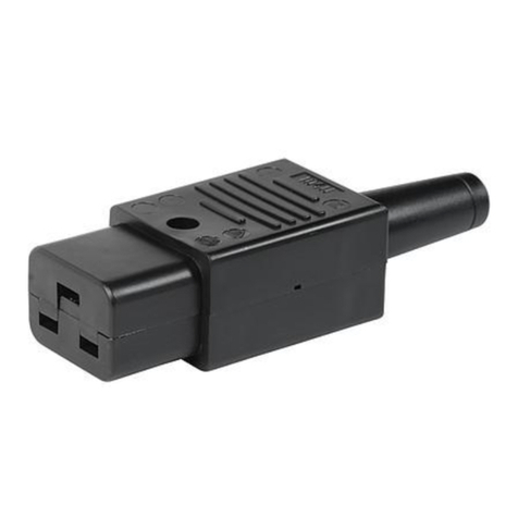
  9. SCHURTER 4795 Series User manual

SCHURTER 4795 Series User manual

1. Wiring for 4795
30
7
7
20
7
30
IN OUT
LL’
PE PE’
NN’
Cable Clamp
Torque Value
0.8Nm
Torque Value
0.4Nm
N blue
L brown
Yellow / green Torque Value
0.5Nm
Cable guard
4795-01XX: cut for
cables over Ø 8.5 mm
Cable end sleeves
(Optional, not enclosed)
Applicable Cable Types
IEC
Type
Cable Type1)
Wire Size
Cable Ø
min.2)
max.
max.
4795
H05VV-F 3G
3x 1.00mm2
3x 1.50mm2
10.4mm
H05RR-F 3G
3x 1.00mm2
3x 1.50mm2
10.4mm
UL
Type
Cable Type3)
Wire Size
Cable Ø
min.
max.
max.
4795
SV…
3x AWG16
3x AWG16
10.4mm
SJ…
3x AWG16
3x AWG14
10.4mm
1) Harmonized wire coding in accordance with IEC60227-5 respectively IEC60245-4.
2) If cord has a length exceeding 2m, nominal cross-sectional areas shall be 1.5mm2or more.
3) Types according to UL 62 which begins with the given letters (i.e. SV… includes SV, SVT, SVE etc.).
owner
vettersa creation date
06.12.2017 release date
08.08.2019 released by
vettersa change order no
2013669 rev
Epage
1 of 2 0115.0048
Operation Manual Wiring for 4795
2. Assembly Instruction
Disconnect power before wiring.
Keep removed piece parts at a safe place to have them ready for reassembling.
1. Loosen cover screw and remove cover.
2. Loosen cable clamp screws and remove cable guard.
3. Insert cord into PVC-cable guard.
4. Remove outer jacket on cord 25 mm. Make sure not to hurt insulation of single conductors.
5. Strip bare each copper conductor 7 mm and crimp on multicore cable ends. Do not strip more than 7 mm.
6. Loosen terminal screws but do not remove screws.
For connecting wires to terminals insert bare ends of conductors from left side of terminal screw according to
figure below. Make sure that no copper strands splice off when connecting conductors to clamps.
correct wrong
P O
P
L / N PE
7. Connect green or green/yellow (ground) wire to center clamp marked with ground symbol.
8. Connect blue (white or light grey) wire to clamp marked „N“ (neutral).
9. Connect brown (black / “hot”) wire to clamp marked „L“ (line).
10. Tighten all wire clamp screws with a torque of 0,8 Nm.
11. Insert shoulder of PVC-cable guard into cutout of base unit.
12. Assemble cable clamp over cut-off end of outer jacket of the cord and tighten cable clamp screws with a
torque of 0,4 Nm.
13. Assemble cover unit and tighten cover screw with a torque of 0,5 Nm.
Warning: Failure to wire as instructed may cause personal injury or damage to device or equipment.
To be installed or checked by an qualified person only.
For factory assembly only.
owner
vettersa creation date
06.12.2017 release date
08.08.2019 released by
vettersa change order no
2013669 rev
Epage
2 of 2 0115.0048
Operation Manual Wiring for 4795
Other SCHURTER Cables And Connectors manuals

SCHURTER 4710-5 User guide

SCHURTER

SCHURTER 4710-5 User guide

SCHURTER 0104U Series User manual

SCHURTER

SCHURTER 0104U Series User manual

SCHURTER 4781 User manual

SCHURTER

SCHURTER 4781 User manual

SCHURTER 9009 User manual

SCHURTER

SCHURTER 9009 User manual

SCHURTER 4762 Series User manual

SCHURTER

SCHURTER 4762 Series User manual

SCHURTER 4796 Series User manual

SCHURTER

SCHURTER 4796 Series User manual

SCHURTER DS11 User manual

SCHURTER

SCHURTER DS11 User manual

SCHURTER 4783 Series User manual

SCHURTER

SCHURTER 4783 Series User manual

SCHURTER 4790 Series User manual

SCHURTER

SCHURTER 4790 Series User manual

Popular Cables And Connectors manuals by other brands

Eaton Roughneck IF 1683 Installation and maintenance information

Eaton

Eaton Roughneck IF 1683 Installation and maintenance information

Freecom CABLE II PARALLEL manual

Freecom

Freecom CABLE II PARALLEL manual

Lindy 32862 Installation and use manual

Lindy

Lindy 32862 Installation and use manual

Chamberlain K001A3200-2 manual

Chamberlain

Chamberlain K001A3200-2 manual

ITK CS3-1C5EU-FPS instructions

ITK

ITK CS3-1C5EU-FPS instructions

Philips SWV2516W Specifications

Philips

Philips SWV2516W Specifications

Amphenol PL182X-301-70-G95 Assembly manual

Amphenol

Amphenol PL182X-301-70-G95 Assembly manual

Georg Fischer MULTI/JOINT 3000 Plus user manual

Georg Fischer

Georg Fischer MULTI/JOINT 3000 Plus user manual

Tellur TLL155374 user manual

Tellur

Tellur TLL155374 user manual

Hama PC-Link-Cable quick start guide

Hama

Hama PC-Link-Cable quick start guide

Lister SB 113 H instruction manual

Lister

Lister SB 113 H instruction manual

Philips IMAGEO 69134/55/PH brochure

Philips

Philips IMAGEO 69134/55/PH brochure

Stahl 8195 Series operating instructions

Stahl

Stahl 8195 Series operating instructions

BrassCraft Safety+PLUS ADVANTAGE Installation instructions manual

BrassCraft

BrassCraft Safety+PLUS ADVANTAGE Installation instructions manual

CYP CH-526RXPL Operation manual

CYP

CYP CH-526RXPL Operation manual

Sensio Gamma SE988950 quick start guide

Sensio

Sensio Gamma SE988950 quick start guide

Monoprice HS-104 owner's manual

Monoprice

Monoprice HS-104 owner's manual

Speaka Professional 98 93 44 operating instructions

Speaka Professional

Speaka Professional 98 93 44 operating instructions

manuals.online logo
manuals.online logoBrands
  • About & Mission
  • Contact us
  • Privacy Policy
  • Terms and Conditions

Copyright 2025 Manuals.Online. All Rights Reserved.