hatch X-RAY User manual

OPERATING MANUAL

HATCH X-RAY Operating Manual
1
Document Number UMN-004627-0-20
Document Revision Rev 01
Publication Language English
Part Number 515-004627-0

THIS PAGE IS LEFT BLANK
INTENTIONALLY
HATCH X-RAY Operating Manual

HATCH X-RAY Operating Manual
3
1 Introduction............................................................................................................ 7
1.1. Hatch X-Ray Equipment................................................................................. 7
1.2. Indication for Use ........................................................................................... 7
1.3. About this Manual........................................................................................... 7
1.4. Included System Components ....................................................................... 8
2 SAFETY AND PRECAUTIONS............................................................................... 9
2.1. Safety Symbols .............................................................................................. 9
3 KNOW YOUR X-RAY UNIT .................................................................................. 11
3.1. Key Component Identication .......................................................................11
3.2. System Labels.............................................................................................. 12
3.3. Hatch X-Ray Reach Dimensions and Movements ....................................... 15
3.4. Hatch X-Ray Wall mount Congurations...................................................... 16
3.5. Keypad Console........................................................................................... 20
4 OPERATING THE UNIT ........................................................................................ 23
4.1. Before You Begin ......................................................................................... 23
4.2. Positioning the Patient ................................................................................. 23
4.3. Achieving the Best Image Quality ................................................................ 24
4.4. Power Turn-On Procedure ........................................................................... 26
4.5. Hatch X-Ray Operating Procedure Summary .............................................. 26
4.6. Exposure Settings and Tables...................................................................... 27
4.7. Exposure Delivery Procedure ...................................................................... 28
5 USING THE CONTROL CONSOLE...................................................................... 37
5.1. Selecting a Pre-set Mode............................................................................. 37
5.2. Selecting a Pre-set....................................................................................... 38
5.3. Modifying Exposure Parameters .................................................................. 39
5.4. Setting the Default Start-up Mode................................................................ 40
5.5. Using Previously Used Exposure Parameters ............................................. 40
5.6. Conguring Accessories............................................................................... 41
5.7. Console Events ............................................................................................ 41
TABLE OF CONTENTS

HATCH X-RAY Operating Manual
4
6 MAINTENANCE .................................................................................................... 45
6.1. Cleaning and Disinfecting ............................................................................ 45
6.2. Caring for your Equipment ........................................................................... 45
6.3. Shipping and Long Term Storage................................................................. 46
6.4. Preventive Maintenance............................................................................... 47
6.5. Disposal of the Unit ...................................................................................... 47
6.6. Optional Accessories.................................................................................... 48
7 TROUBLESHOOTING .......................................................................................... 49
Annex A TECHNICAL SPECIFICATIONS ............................................................... 51
Annex B DECLARATION OF CONFORMITY ......................................................... 57
Annex C GUIDANCE AND MANUFACTURER’S DECLARATION......................... 59
Annex D CONTACT DETAILS................................................................................. 65

List Of Figures
Figure 1 : Identication of Wall Mount ..........................................................................12
Figure 2 : Label Location..............................................................................................14
Figure 3 : Wall Mounted Hatch X-Ray Fully Extended Right Side and Top Views .......15
Figure 4 : Wall Mounted Hatch X-Ray Ground Clearance............................................15
Figure 5 : Wall Mounted Hatch X-Ray Vertically Extended .........................................16
Figure 6 : Hatch X-Ray Keypad Console with LCD Display ........................................21
Figure 7 : Horizontal Angulation ...................................................................................25
Figure 8 : Paralleling Technique ...................................................................................25
Figure 9 : Home screen................................................................................................28
Figure 10 : X-Ray - Ready............................................................................................28
Figure 11 : X-Ray - Exposing........................................................................................28
Figure 12 : X-Ray - results............................................................................................29
Figure 13 : Start-up screen...........................................................................................37
Figure 14 : Home screen..............................................................................................37
Figure 15 : Mode selection screen ..............................................................................38
Figure 16 : Home screen with mS highlighted..............................................................39
Figure 17 : mS parameter being modied (blinking).....................................................39
Figure 18 : mS parameter modied and accepted, kV highlighted...............................39
Figure 19 : Setting a Start-up Mode .............................................................................40
Figure 20 : History screen ............................................................................................40
Figure 21 : Conguration Screen..................................................................................41
Figure 22 : Stand-by screen .........................................................................................41
Figure 23 : Error display ...............................................................................................41
Figure A-1 : X-Ray Tube Insert Rating Chart-OX/70-4 .................................................52
Figure A-2 : X-Ray Tube Insert Thermal data-OX/70-4 ................................................53
Figure A-3 : Heating and cooling curve - Product’s tube inserts-OX/70-4....................53

HATCH X-RAY Operating Manual
6
List Of Tables
Table 1: Hatch X-Ray System Components .................................................................8
Table 2 : Default exposure values for short / long cone slow lm – Mode 1.................30
Table 3 : Default exposure values for short / long cone fast lm – Mode 1..................31
Table 4 : Default exposure values for short / long cone – Mode 2 ...............................32
Table 5 : Default exposure values – PSP (Short Cone)................................................33
Table 6 : Default exposure values – PSP (Long Cone) ................................................34
Table 7 : Default exposure values – Custom modes (All).............................................35
Table 8 : Attention / Warning Messages .......................................................................43
Table 9 : Tube seasoning..............................................................................................46
Table 10 : Hatch X-Ray Optional Accessories..............................................................48
Table 11 : Error codes ..................................................................................................49
Table 12 : Troubleshooting tips.....................................................................................50
Table A1 : Tube-Head specications ............................................................................52
Table A2 : X-Ray tube insert specications ..................................................................52
Table A3 : Mechanical dimensions and weight.............................................................54
Table A4 : Mains power requirements ..........................................................................55
Table A5 : Environmental conditions ............................................................................55
Table C1 : Guidance and Manufacturer’s Declaration – Electromagnetic Emissions...59
Table C2 : Guidance and Manufacturer’s Declaration – Electromagnetic Immunity – For
all EQUIPMENT and SYSTEMS .................................................................61
Table C3 : Guidance and manufacturer’s declaration – Electromagnetic immunity - for
all EQUIPMENT and SYSTEMS that are not LIFE-SUPPORTING.............63

HATCH X-RAY Operating Manual
7
1.1. Hatch X-Ray Equipment
Congratulations, your new Hatch X-Ray High Frequency Intraoral X-Ray has
been engineered and manufactured to provide many years of reliable service.
The system houses two microprocessors, one for control/supervisory functions
and another to provide the user/machine interface. The technology incorporates
feedback circuits to ensure accuracy and reproducibility of X-Ray output for dental
diagnostic radiography. Hatch X-Ray will create radiographs of excellent quality,
performing equally well using any image receptor.
The High Frequency Intraoral X-Ray is hereafter referred to as Hatch X-Ray in
this manual. Review and follow the guidelines included in this Users’ Manual to
thoroughly become familiar with the operating and safety procedures. This will
ensure that your Hatch X-Ray gives you the highest level of service.
1.2. Indication for Use
The Hatch X-Ray High Frequency Intraoral X-Ray is to be used as a source of
X-Rays in Dental radiography. Only trained professionals should use this device.
Federal law prohibits the sale of this device to individuals other than trained
professionals. Use of this device, other than as described in this manual, may
result in injury.
The expected service life of the product is determined based on design
considerations and eld performance of similar devices. The expected service
life dened as minimum 10 years during which the device is expected to remain
suitable for its INTENDED USE. It is also the period when all RISK CONTROL
measures will remain eective to ensure that RISKS remain acceptable.
1.3. About this Manual
This manual is not to be used as a replacement for training in radiography. The
document contains basic operation instructions, identication of parts, system
labels and safety guidelines for the Hatch X-Ray models listed below. Additionally,
troubleshooting tips are provided should the equipment not perform as intended.
The following are guidelines for using this manual.
CAUTION
Alerts users to important instructions that require caution when
operating the unit since they are related to safety
CHAPTER
1INTRODUCTION

HATCH X-RAY Operating Manual
8
NOTE
This symbol points to an important detail / tip in the operation of the
unit. Read carefully to avoid any problems.
This manual describes the user interface of the control console
using images as displayed on the left. These images are
indicative only and the values displayed may dier from the
actual values unless specied otherwise.
1.4. Included System Components
The Wall Mounted Hatch X-Ray system is available in three model congurations
using dierent Extension arm assembly. Unpack each component and verify that
items listed below are received as appropriate. If any item is missing or damaged,
notify your authorized dealer.
Table 1: Hatch X-Ray System Components
Wall Mounted
Description Part No.
Hatch X-Ray X-RAY, FS04,Wall Mount, 15” Extension arm F303-002381-0
Hatch X-Ray X-RAY, FS04,Wall Mount, 24” Extension arm F303-002382-0
Hatch X-Ray X-RAY, FS04,Wall Mount, 33” Extension arm F303-002383-0
Extension arm Assembly - one only
(Used with Wall Mount Units Only)
15 Inches Long (used on Model P/N-15)
24 Inches Long (used on Model P/N-24)
33 Inches Long (used on Model P/N-33)
Note: The Tubehead is shipped attached to the Scissor Arm
Scissor Arm Assembly (includes cables)
70kVp 8mA Tubehead Assembly
Base Unit Assembly
Control Console with Cable
Template for Single and Two Stud Wall Plate Installations
Template for Remote Wall Plate Installations
Remote Keypad Console (Optional)
Remote Doorbell Switch

HATCH X-RAY Operating Manual
9
CAUTION
• Users must exercise every precaution to ensure personnel
safety, and be familiar with the warnings and cautions
presented throughout this manual and summarized below.
• Make sure to read and understand the safety related
instructions.
• Make sure not to modify any component of the Hatch X-Ray
system. Any modication may result in violation of compliance
to the standards. Hatch X-Ray shall not be responsible for any
modication causing violation of compliance, compromise on
safety, performance deterioration or any other adverse eects.
• Warranty of this equipment will be void in the event of any
modication done to the equipment, misuse of the equipment
and opening or servicing by unauthorized personnel.
2.1. Safety Symbols
The following safety related symbols are found on the equipment.
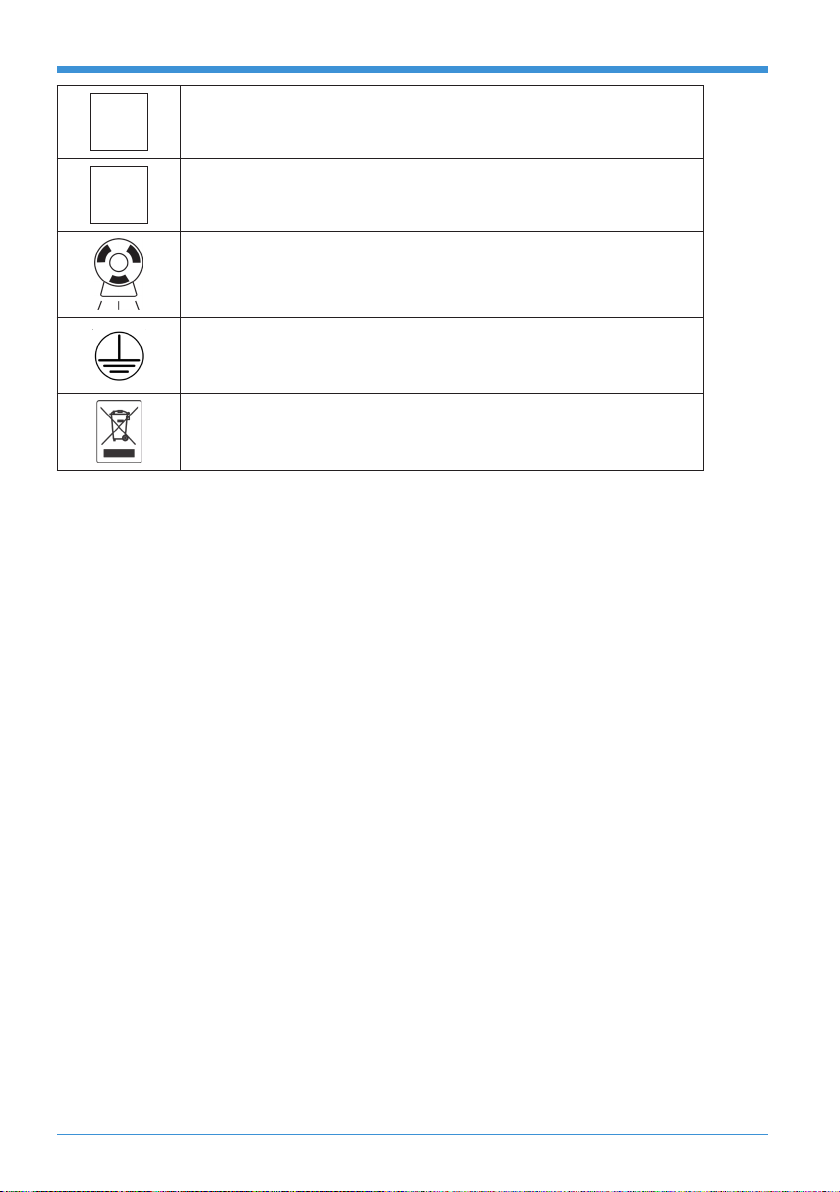
Caution Symbol
This symbol indicates the user to be cautious and refer to the
user manual for safe operating instructions.
Type of Insulation
Class 1, Type B Insulation. Protection against electric shock
(UL60601-1:2003). Requires protective earth connection.
High Voltage
Dangerous voltages present.
Caution: X-Ray
X-Ray source assembly/Tube Head capable of generating
X-Rays. This X-Ray unit may be dangerous to patient & operators
unless safe exposure factors and operating instructions are
observed.
Follow Instructions for use.
Focal Spot.
CHAPTER
2SAFETY AND PRECAUTIONS
HATCH X-RAY Operating Manual
10
LMains Line Connection.
NMains Neutral Connection.
X-Ray Emission/ON.
Protective earth
Mains Earth is required for continued protection against shock
hazards.
WEEE Symbol
Follow proper procedures for disposing this equipment. Cannot
be disposed as general waste.

HATCH X-RAY Operating Manual
11
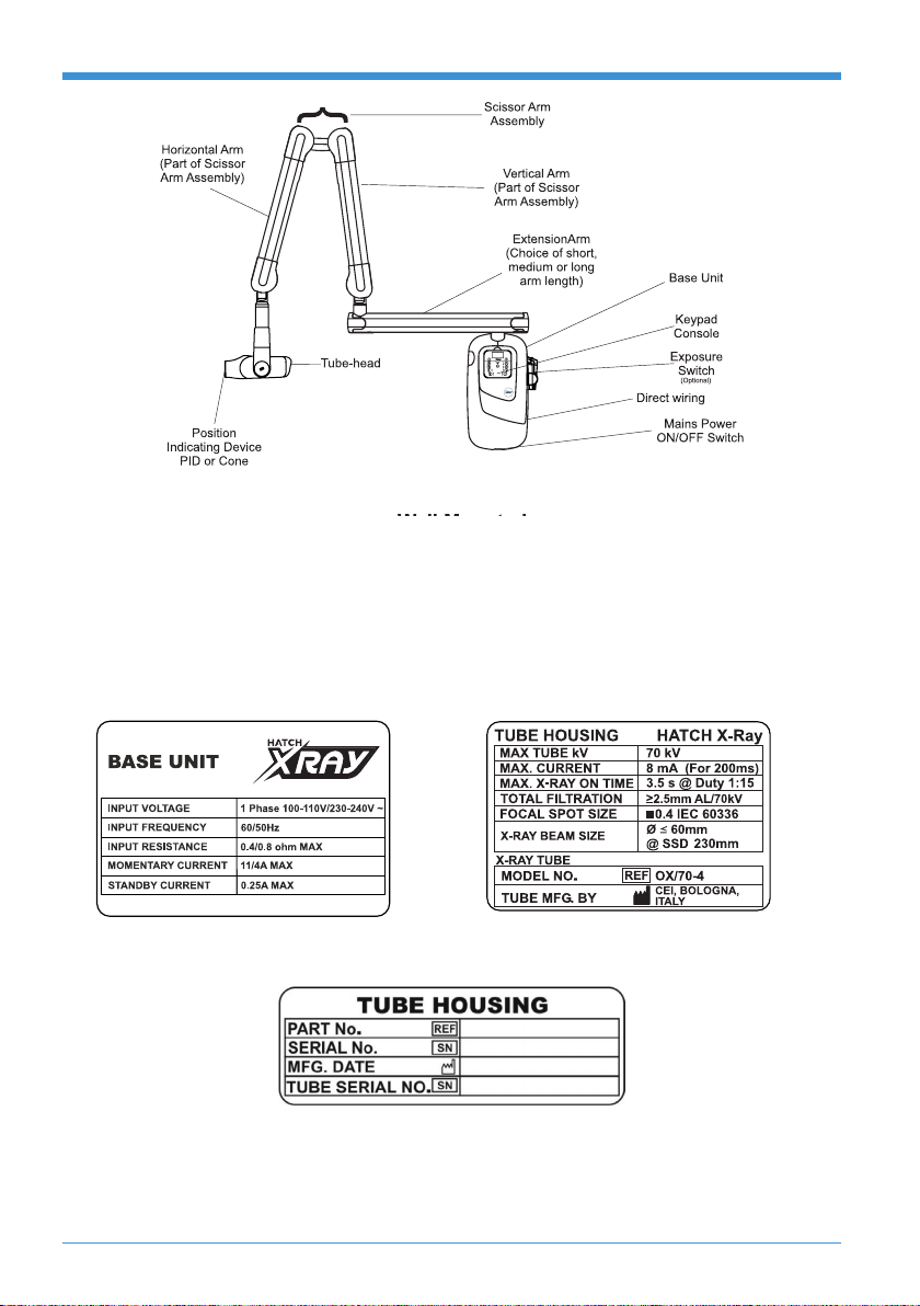
3.1. Key Component Identication
As shown in “Figure 1”, Hatch X-Ray is comprised of the following components:
1. Base Unit
The Base Unit provides mounting support for the Extension arm and scissor
arm with attached tube-head. It provides system power connection and
application via the Mains Power Line Cord and the Mains Power ON/OFF
Switch. Overall operational control for Hatch X-Ray is also provided via the
Keypad Console.
2. Keypad Console
The Keypad Console is the user/machine interface providing all functional
operating control of the Hatch X-Ray system. Consisting of an LCD display
and keypad, the console keypad allows both automatic and manual selections
of exposure parameters while the resultant operation status is shown via the
LCD display.
3. Extension arm
The Extension arm provides the horizontal space away from the wall-mounted
Base Unit. Available in 15, 24 and 33 - inch lengths to meet the reach
requirements of the installation site.
4. Scissor Arm
The Scissor Arm consists of a vertical and horizontal arm joined via a double
joint. This design enables smooth linear and upward motion transitions while
allowing the attached tube-head to remain balanced in all positions.
5. Tube-head with Beam Limiting Device
Provides 60 kV – 70 kV voltage range (adjustable in 1 kV steps) and 4 mA – 8
mA current range (adjustable in 1 mA steps) to reduce exposure times and the
amount of radiation absorbed by the patient. The tube-head is equipped with a
beam limiting device with a 23 cm (8.98 inches) source to skin distance and 6
cm (2 ⅜ inches) beam diameter at the output. The tube-head is connected to
the arm by means of a rotating contact, allowing 540 degree horizontal rotation
and 310 degree vertical rotation.
CHAPTER
3 KNOW YOUR X-RAY UNIT
HATCH X-RAY Operating Manual
12
Figure 1 : Identication of Wall Mount
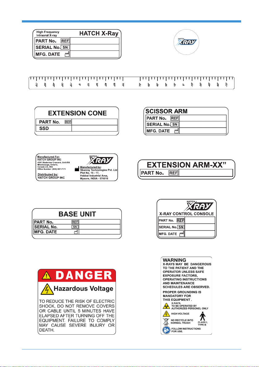
3.2. System Labels
This section lists the labels that are axed on the unit. Please refer to “Figure 2”
for the location where they are axed. The mark number is given against each
label below.
Label 1 : Base Unit Label Label 2 : Tube Housing Label for focal spot 0.4
Label 3 : Tube Housing Sl. No. Label
HATCH X-RAY Operating Manual
13
Label 4 : System Label Label 5 : Hatch X-Ray Logo
Label 6 : Angular Tape
Label 7 :
Extension Cone Label
Label 8 : Scissor Arm Label
Label 9 : Manufacturer Label Label 10 : Extension Arm Label
Label 11 : Base Unit Sl. No. Label Label 12 : Console Label
Label 13 : Danger Label Label 14 : Warning Label

HATCH X-RAY Operating Manual
14
Label 15 : Radiation Caution Label Label 16 : UDI Label
Label 17 : UL Mark Label Label 18 : Input Conguration Label
Figure 2 : Label Location

HATCH X-RAY Operating Manual
15
3.3. Hatch X-Ray Reach Dimensions and Movements
“Figure 3” to “Figure 5” show minimum and maximum clearances and dimensions
for wall mounted.
Figure 3 : Wall Mounted Hatch X-Ray Fully Extended Right Side and Top Views
Extension Arm Lenght - A Max. Reach to Wall - B
15”(381mm) 62”(1575mm)
24”(610mm) 71”(1803mm)
33”(838mm) 80”(2032mm)
Figure 4 : Wall Mounted Hatch X-Ray Ground Clearance

HATCH X-RAY Operating Manual
16
Figure 5 : Wall Mounted Hatch X-Ray Vertically Extended
*15”/24”/33” Support Tube.
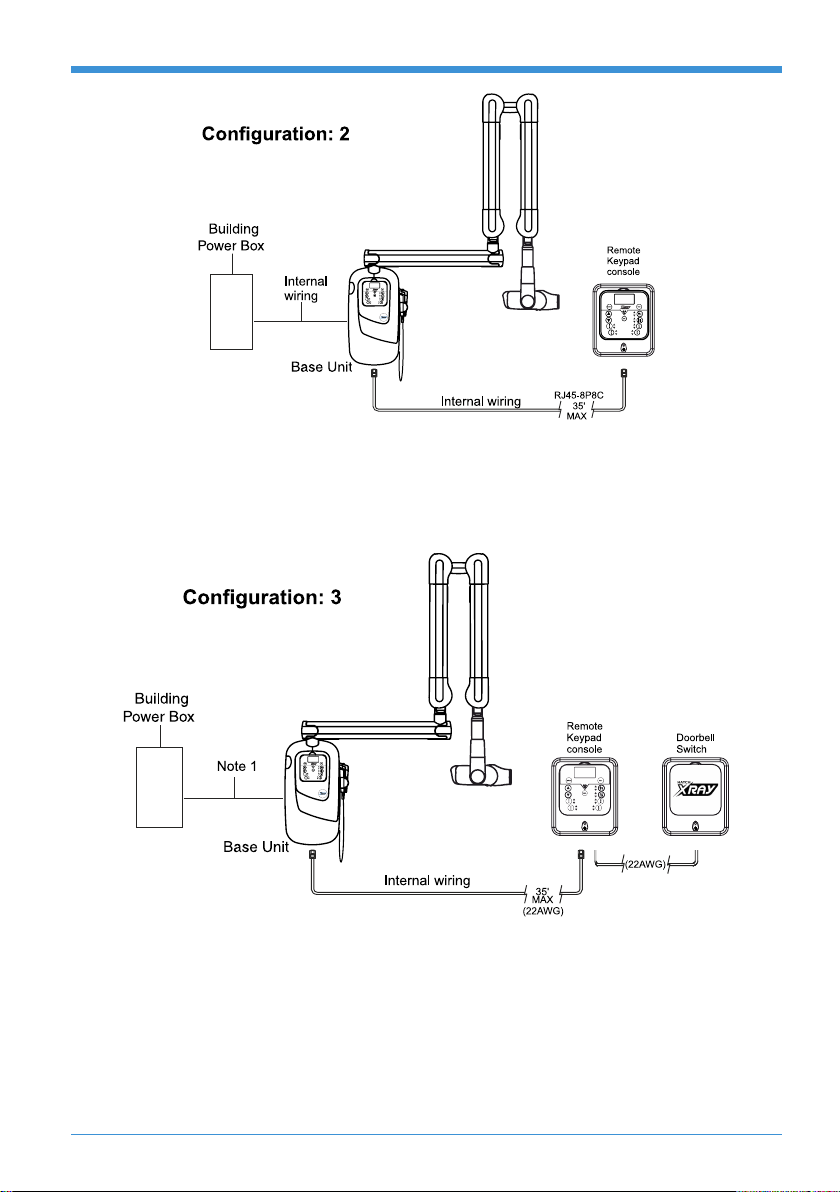
3.4. Hatch X-Ray Wall mount Congurations
Can use Internal Keypad Console and Internal Exposure Switch (Optional)
NOTE
For Congurations 2 - 7
• RJ45-8P8C 35’ Cable: CAT-5 24AWG 4-Twisted Pair 1:1
Connection.
• RJ11-6P4C 35’ Cable: Center 4 Positions Populated 1:1
Connection.
• 3Wire, 35’ Cable: Shielded or Un-shielded Cable AWG 20-28.
HATCH X-RAY Operating Manual
17
RJ45 (8P8C) with single door bell switch (optional)
Can use both Keypad Consoles (internal and remote) with Internal Exposure
Switch and single door bell switch.
RJ45 (8P8C) with DOUBLE DOORBELL SWITCH (optional)
Can use both Keypad Consoles (internal and remote) with Internal Exposure
Switch and double door bell switch:

HATCH X-RAY Operating Manual
18
3 WIRE WITH SINGLE DOORBELL SWITCH
Can use Internal Keypad Console with Internal Exposure Switch and single
door bell switch
3 WIRE WITH DOUBLE DOORBELL SWITCH (optional)
Can use Internal Keypad Console with Internal Exposure Switch and double
door bell switch
HATCH X-RAY Operating Manual
19
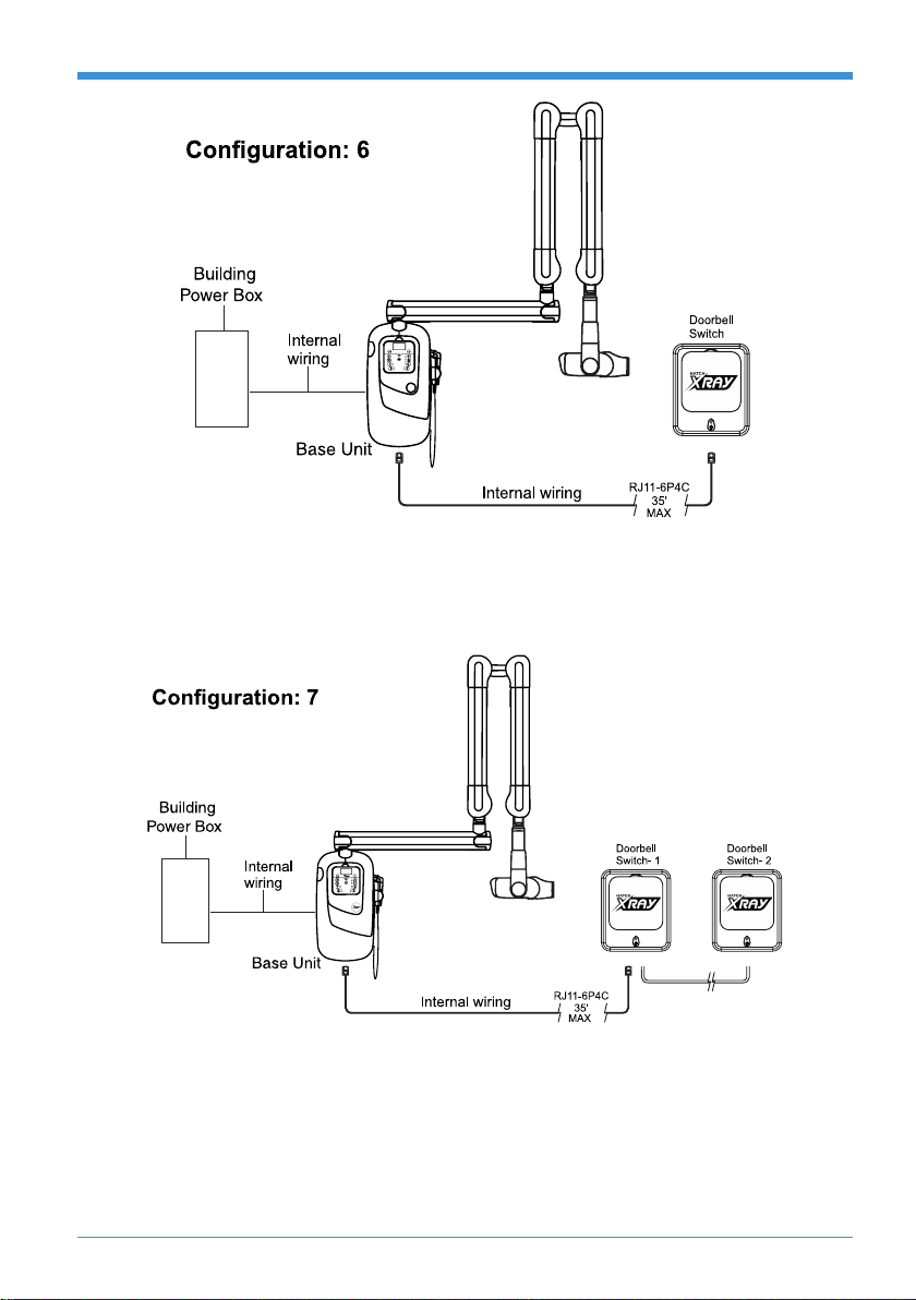
RJ11 (6P4C) WITH SINGLE DOORBELL SWITCH
Can use Internal Keypad Console with Internal Exposure Switch and single
door bell switch
RJ11 (6P4C) WITH DOUBLE DOORBELL SWITCH (optional)
Can use Internal Keypad Console with Internal Exposure Switch and double
door bell switch
Table of contents
Other hatch Dental Equipment manuals

Popular Dental Equipment manuals by other brands


DENTSPLY
DENTSPLY AEU-25T Operation and maintenance instruction manual

Tiger Dental
Tiger Dental PowerScrew 8 Instructions for use

Planmeca
Planmeca Proline XC user manual

Renfert
Renfert SILENT powerCAM TC quick start guide

Woodpecker
Woodpecker Ai-Motor instruction manual

Patterson
Patterson 043-2047 Operation manual


