Hatco Rapide Cuisine IRNGBD Series User manual

P/N 07.04.1065.00 © 2023 Hatco Corporation
Rapide Cuisine®
Do not operate this equipment unless you
have read and understood the contents
of this manual! Failure to follow the
instructions contained in this manual
may result in serious injury or death.
This manual contains important safety
information concerning the maintenance,
use, and operation of this product. If
you’re unable to understand the contents
of this manual, please bring it to the
attention of your supervisor. Keep this
manual in a safe location for future
reference.
WARNING
No opere este equipo al menos que haya
leído y comprendido el contenido de este
manual! Cualquier falla en el seguimiento
de las instrucciones contenidas en
este manual puede resultar en un serio
lesión o muerte. Este manual contiene
importante información sobre seguridad
concerniente al mantenimiento, uso y
operación de este producto. Si usted
no puede entender el contenido de
este manual por favor pregunte a su
supervisor. Almacenar este manual en
una localización segura para la referencia
futura.
ADVERTENCIA
Ne pas utiliser cet équipement sans avoir
lu et compris le contenu de ce manuel ! Le
non-respect des instructions contenues
dans ce manuel peut entraîner de
graves blessures ou la mort. Ce manuel
contient des informations importantes
concernant l’entretien, l’utilisation et le
fonctionnement de ce produit. Si vous ne
comprenez pas le contenu de ce manuel,
veuillez le signaler à votre supérieur.
Conservez ce manuel dans un endroit
sûr pour pouvoir vous y référer plus tard.
AVERTISSEMENT
Original Instructions
Instrucciones originales
Instructions originales
Dual Induction Ranges
IRNGCD/IRNGBD Series, P Type
Installation and Operating Manual
For CE and Non-CE Models
P 2
Hornallas de inducción dobles
IRNGCD/IRNGBD Serie, tipo P
Manual de Instalación y Operación
Para modelos CE y no CE
P 20
Plaques àInduction Doubles
IRNGCD/IRNGBD Série, Type P
Manuel d’installation et d’utilisation
Pour les modèles CE et non-CE
P 40

IRNGCDCEM1-0123
2
CONTENTS
Safety information that appears in this manual is identified by
the following signal word panels:
WARNING
WARNING indicates a hazardous situation
which, if not avoided, could result in death
or serious injury.
CAUTION
CAUTION indicates a hazardous situation
which, if not avoided, could result in minor
or moderate injury.
NOTICE
NOTICE is used to address practices not
related to personal injury.
NOTE: Refer to the Symbol Identification tables on the back
cover of this manual for definitions of symbols that may
appear in this manual.
INTRODUCTION
Hatco Dual Induction Ranges offer a safe, quick, efficient,
and attractive way to prepare foods in commercial kitchens as
well as display cooking locations (omelet bars, buffets, etc...).
The high efficiency, accuracy, and speed of induction cooking
make Hatco Induction Ranges the perfect choice for quality
foodservice organizations.
Induction cooking relies on the creation of a magnetic field
between the induction coils below the glass surface of the
unit and an “induction-ready” pan sitting on top of the glass
surface. This magnetic field generates induction currents in
the base of the pan, which heat the pan instantly. That heat
then is transferred to the pan contents. Since the magnetic field
exists only between the induction coils and a magnetic material
(ferrous material), the glass surface between the two does not
become heated, eliminating heat loss and increasing efficiency.
When the magnetic field is “broken” by turning off the unit or
removing the pan, heat generation stops instantly.
Hatco Dual Induction Ranges are products of extensive research
and field testing. The materials used were selected for maximum
durability, attractive appearance, and optimum performance.
Every unit is inspected and tested thoroughly prior to shipment.
This manual provides the installation, safety, and operating
instructions for Hatco Dual Induction Ranges. Hatco
recommends all installation, operating, and safety instructions
appearing in this manual be read prior to installation or
operation of a unit.
Important Owner Information..............................................2
Introduction...........................................................................2
Important Safety Information ..............................................3
Model Designation ...............................................................4
Model Description ................................................................5
Specifications .......................................................................6
Plug Configurations .............................................................6
Electrical Rating Charts.......................................................6
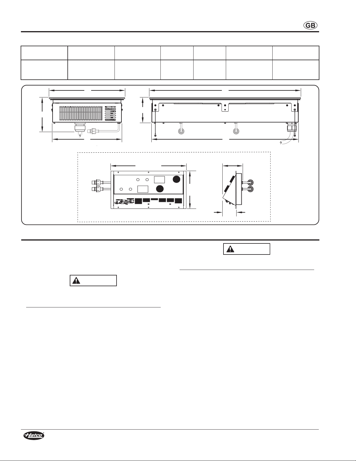
Dimensions .........................................................................7
Installation.............................................................................8
General................................................................................8
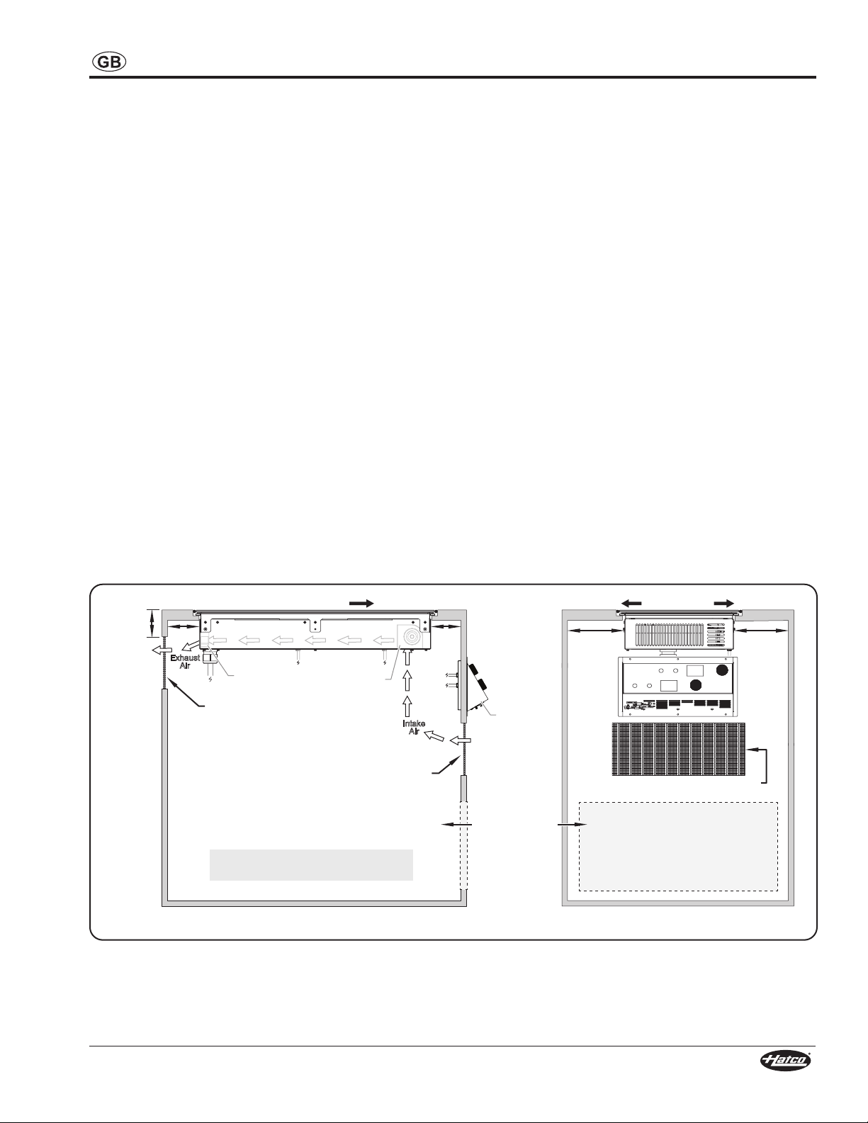
Installing Built-In Models .....................................................9
Installing the Control Panel ............................................... 11
Operation.............................................................................12
General..............................................................................12
Changing Cooking Control Method ...................................13
Using the Timer .................................................................14
Cooking with Menu Items..................................................14
Programming Menu Items .................................................15
Changing Operation Mode ................................................15
Changing Between Fahrenheit and Celsius......................16
Resetting the Software ......................................................16
Updating Firmware ............................................................16
Maintenance........................................................................17
General..............................................................................17
Daily Cleaning ...................................................................17
Troubleshooting Guide ......................................................18
Service Information............................................................18
International Limited Warranty .........................................19
IMPORTANT OWNER INFORMATION
Record the model number, serial number, voltage, and purchase
date of your strip heater in the spaces below (specification
label located on the underside of the unit). Please have this
information available when calling Hatco for service assistance.
Model No. ________________________________________
Serial No._________________________________________
Voltage___________________________________________
Date of Purchase___________________________________
Register your unit!
Completing online warranty registration will prevent delay in
obtaining warranty coverage. Access the Hatco website at
www.hatcocorp.com, select the Support pull-down menu,
and click on “Warranty”.
Business
Hours: 7:00 to 5:00 Monday–Friday,
Central Time (CT)
(Summer Hours—June to September:
7:00 to 5:00 Monday–Thursday
7:00 to 4:00 Friday)
Telephone: +1-414-671-6350
E-mail: [email protected]
Additional information can be found by visiting our web site at
www.hatcocorp.com.
Correct Disposal of this Product
This marking indicates that this product and its electronic
components should not be disposed of with other
commercial waste. To prevent possible harm to the
environment or human health from uncontrolled waste
disposal, recycle responsibly to promote the sustainable
reuse of material resources. To dispose of product and its
electronic components, contact supplier where product
was purchased for environmentally safe recycling.

IRNGCDCEM1-0123 3
IMPORTANT SAFETY INFORMATION
WARNING
ELECTRIC SHOCK HAZARD: Use only
Genuine Hatco Replacement Parts when
service is required. Failure to use Genuine
Hatco Replacement Parts will void all
warranties and may subject operators of the
equipment to hazardous electrical voltage,
resulting in electrical shock or burn. Genuine
Hatco Replacement Parts are specified
to operate safely in the environments in
which they are used. Some after-market
or generic replacement parts do not have
the characteristics that will allow them to
operate safely in Hatco equipment.
EXPLOSION HAZARD: Do not heat unopened
containers of food on unit. Sealed, heated
containers may burst open.
ELECTROMAGNETIC INTERFERENCE
HAZARD: This unit generates close-range
electromagnetic fields. It has been designed
to meet the applicable standards for non-
interference with other electronic devices.
Make sure ot her electronic devices in the
vicinity, including pacemakers and other
active implants, have been designed to meet
their corresponding applicable standards.
As a precaution, do not operate unit or
come within 305 mm (12ʺ) of unit with a
pacemaker or other active implant.
FIRE HAZARD:
• Make sure to follow the installation
information listed below for specific
induction ranges. If safe distances are not
maintained, discoloration or combustion
could occur.
a. Locate countertop unit a minimum of
51 mm (2″) from combustible walls and
materials.
b. Locate built-in unit with a minimum of
38 mm (1-1/2″) between sides of unit
and any interior surface.
c. Locate built-in unit with a minimum of
51 mm (2″) between front and back of
unit and any interior surface.
d. Locate built-in unit with a minimum of
114 mm (4-1/2″) between bottom of unit
and any interior surface.
• Do not obstruct air ventilation openings
on sides and bottom of unit. Unit
combustion or malfunction may occur.
• Do not place unit near or underneath
curtains or other combustible materials.
Items near or above unit could catch fire
causing injury and/or damage to unit.
WARNING
ELECTRIC SHOCK HAZARD:
• Plug unit into a properly grounded
electrical receptacle of the correct
voltage, size, and plug configuration. If
plug and receptacle do not match, contact
a qualified electrician to determine and
install proper voltage and size electrical
receptacle.
• Remote mounted control panel must be
mounted on a vertical wall and installed
in vertical position. Mounting control
panel in horizontal position may result
in collection of liquids and lead to an
electric shock.
• Turn OFF power switch, unplug power
cord, and allow unit to cool before
performing any cleaning, adjustments,
or maintenance.
• DO NOT submerge or saturate with water.
Do not allow liquids to spill into unit. Unit
is not waterproof. Do not operate if unit
has been submerged or saturated with
water.
• Unit is not weatherproof. Locate unit
indoors where ambient air temperature is
a minimum of 21°C (70°F) and a maximum
of 51°C (124°F).
• Do not steam clean or use excessive
water on the unit.
• This unit is not “jet-proof” construction.
Do not use jet-clean spray to clean this
unit.
• Do not clean unit when it is energized or
hot.
• Do not pull unit by power cord.
• Discontinue use if power cord is frayed
or worn.
• Do not attempt to repair or replace
a damaged power cord. Cord must
be replaced by an Authorized Hatco
Service Agent or a person with similar
qualifications.
• This unit must be serviced by qualified
personnel only. Service by unqualified
personnel may lead to electric shock or
burn.
Read the following important safety information before using this equipment to avoid
serious injury or death and to avoid damage to equipment or property.

IRNGCDCEM1-0123
4
IMPORTANT SAFETY INFORMATION
WARNING
This unit is not intended for use by children
or persons with reduced physical, sensory,
or mental capabilities. Ensure proper
supervision of children and keep them away
from unit.
Make sure all operators have been instructed
on the safe and proper use of the unit.
This unit has no “user-serviceable” parts.
If service is required on this unit, contact
an Authorized Hatco Service Agent or
contact the Hatco Service Department at
+1-414-671-6350.
CAUTION
BURN HAZARD:
• Do not leave metal objects or utensils
on or near induction range. They may
become hot.
• Use caution when wearing rings, watches,
or other ferrous objects around induction
range. They may become hot.
• Some exterior surfaces on unit will get
hot. Use caution when touching these
areas.
Do not block or restrict air flow to air intake
or exhaust openings on bottom of unit.
Do not store anything on top of unit.
Locate unit at proper counter height in an
area that is convenient for use. Location
should be level to prevent unit or its contents
from falling accidentally and strong enough
to support weight of unit and contents.
NOTICE
Plug unit into a dedicated circuit. Do not use
multiple appliances on same circuit.
Never use aluminum foil on induction range.
Aluminum foil will melt and damage unit.
Do not place objects with magnetic
properties (credit cards, cassette tapes,
etc...) on or near unit during operation.
Use only wipes, pads, and cleaners designed
specifically for cleaning ceramic glass
surfaces.
Use non-abrasive cleaners and cloths only.
Abrasive cleaners and cloths could scratch
finish of unit, marring its appearance and
making it susceptible to soil accumulation.
Do not locate unit in area with excessive
air movement around unit. Avoid areas that
may be subject to active air movements or
currents (i.e., near exhaust fans/hoods, air
conditioning ducts, and exterior doors).
This unit is intended for commercial use
only—NOT for household use.
I R N G - P x 2 x - x x
Induction Maximum Wattage/Coil
16 = 1560 W
18 = 1800 W
36 = 3600 W
S = Side-by-Side
F = Front-to-Back
Programmable
Range
C = Countertop
B = Built-In
Dual Coil
MODEL DESIGNATION

IRNGCDCEM1-0123 5
MODEL DESCRIPTION
All Models
Hatco P Type Dual Induction Ranges are equipped with two
induction coils underneath a single ceramic glass cooking
surface, enabling the use of two pans on a single unit. Each
model features a glass touch control panel. The control panel
has separate, identical controls for each coil including a
Function Button, a Timer Button, a Control Knob, and a Control
Display. All P Type Induction Ranges include an attached
NOTE: Refer to “Pan Specifications” in the OPERATION section
of this manual for details on “induction-ready” pans,
pans not suitable for induction cooking, and pan sizes.
Hatco P Type Dual Induction Ranges have several safeguards
built into each unit that ensure protection to the unit as well as
the operators.
• A cross-flow fan ventilation system ensures that the
electronic circuits in the unit do no overheat. Temperature
probes monitor the electronic circuits and will signal the
unit to shut down if the circuits get too hot.
• Temperature probes in the cooking zones monitor the
zone temperature. These probes detect overheating in the
cooking zone due to an empty pan.
• Electronic circuitry in the cooking zones detect when a
small, ferrous object (such as a fork, spoon, or ring) is
placed on the unit, and the unit will not operate.
Countertop Models
Countertop P Type Dual Induction Ranges models are portable,
countertop induction ranges.
IRNG-PC2S-xx Models
IRNG-PC2S-xx models are side-by-side dual induction ranges.
The induction coils are designated as the left coil and the right
coil. The control panel for each coil is directly in front of its
corresponding coil.
Timer
Button
Function Button Power/Control Knob
Control Display
Ceramic Glass
Cooking Surface
Left Coil Right Coil
Side-by-Side Dual Countertop Model
IRNG-PC2F-xx Models
IRNG-PC2S-xx models are front-to-back dual induction ranges.
The induction coils are designated as the front coil and the back
coil. The control panel for each coil is designated by a graphic
on the control label—the top control panel controls the front
coil, and the bottom control panel controls the back coil.
Ceramic Glass
Cooking Surface
Timer
Button
Function
Button
Power/Control
Knob
Control Display
Front Coil
Back Coil
Front-to-Back Dual Countertop Model
Built-In Models
Built-In P Type Dual Induction Ranges are designed to be
installed into a variety of solid material countertops. The unit
includes a remote control panel that connects to the induction
range with detachable control cables that combine for a total
Ceramic Glass
Cooking Surface
Timer
Button
Function
Button
Power/Control
Knob
Control Display
Front Coil
Back Coil
Remote
Control
Panel
Control
Cables
P Type Dual Built-In Model
NOTE: For the latest firmware updates, cooking tips, and
more, go to the Hatco Induction Range website:
www.hatcocorp.com/rapide_cuisine

IRNGCDCEM1-0123
6
Model Voltage Total Watts Amps Hertz Plug Configuration Shipping Weight
IRNG-PC2S-16 and
IRNG-PC2F-16
220–230–240 2860–2990–3120 13 50–60 BS-1363 19 kg (41 lbs.)
220 2860 60
IRNG-PC2S-18 and
IRNG-PC2F-18 220–230–240 3300–3450–3600 16 50–60 CEE 7/7 Schuko
19 kg (41 lbs.)
15 AS 3112
220 3300 50 CCC 16 A
IRNG-PC2S-36 and
IRNG-PC2F-36
220–230–240 6600–6900–7200 30 50–60 IEC 60309, 2P + E 19 kg (41 lbs.)
220 6600 60
SPECIFICATIONS
Electrical Rating Chart—Countertop Models
Electrical Rating Chart—Built-In Models
Plug Configurations
Units are supplied from the factory with an electrical cord and
plug installed. Plugs are supplied according to the application.
WARNING
ELECTRIC SHOCK HAZARD: Plug unit into a properly
grounded electrical receptacle of the correct voltage,
size, and plug configuration. If plug and receptacle do not
match, contact a qualified electrician to determine and
install proper voltage and size electrical receptacle.
NOTE: The specification label is located on the bottom of the
unit. See label for serial number and verification of unit
electrical information.
CEE 7/7 Schuko AS 3112
BS-1363
CCC 16 A
IEC 60309
2P + E
Plug Configurations
NOTE: Receptacle not supplied by Hatco. All units must be
connected to a dedicated circuit.
NOTE: Shipping weight includes packaging.
Model Voltage Total Watts Amps Hertz Plug Configuration Shipping Weight
IRNG-PB2-16 220–230–240 2860–2990–3120 13 50–60 BS-1363 19 kg (41 lbs.)
220 2860 60
IRNG-PB2-18
220–230–240 3300–3450–3600 16 50–60
CEE 7/7 Schuko,
CCC 16 A 19 kg (41 lbs.)
15 AS 3112
IRNG-PB2-36 220–230–240 6600–6900–7200 30 50–60 IEC 60309, 2P + E 19 kg (41 lbs.)
220 6600 60

IRNGCDCEM1-0123 7
Model Width (A) Depth (B) Height (C)
Footprint
Width (D)
Footprint
Depth (E)
Cooking Surface
Width (F)
Cooking Surface
Depth (G)
IRNG-PC2F-16
IRNG-PC2F-18
IRNG-PC2F-36
356 mm
753 mm
133 mm
313 mm
655 mm
348 mm
622 mm
Model Width (A) Depth (B) Height (C)
Footprint
Width (D)
Footprint
Depth (E)
Cooking Surface
Width (F)
Cooking Surface
Depth (G)
IRNG-PC2S-16
IRNG-PC2S-18
IRNG-PC2S-36
630 mm
484 mm
122 mm
593 mm
361 mm
622 mm
348 mm
SPECIFICATIONS
Dimensions—IRNG-PC2S-xx Models
Dimensions—IRNG-PC2F-xx Models
G
F
Top View
A
D
Front View
C
B
E
Side View
C
B
E
Front View
Side View
Top View
A
D
G
F

IRNGCDCEM1-0123
8
Model Cooking Surface
Width (A) Cooking Surface
Depth (B) Height (C) Unit
Height (D) Under-Counter
Width (F) Under-Counter
Depth (G)
IRNG-PB2-16
IRNG-PB2-18
IRNG-PB2-36
350 mm
699 mm
157 mm
116 mm
320 mm
679 mm
Dimensions—IRNG-PB2-xx Models
A B
C
349 mm
(13-3/4")
93 mm
(3-11/16")
67 mm
(2-5/8")
174 mm
(6-7/8")
D
E F
Front View
Remote Control Panel
SideView
SPECIFICATIONS
General
Dual Induction Ranges are shipped completely assembled and
ready for use. Built-in units require installation into a countertop
(see procedures in this section). Care should be taken when
unpacking the shipping carton to avoid damage to the unit.
WARNING
ELECTRIC SHOCK HAZARD: Unit is not weatherproof.
Locate unit indoors where ambient air temperature is a
minimum of 21°C (70°) and a maximum of 51°C (124°F).
FIRE HAZARD:
• Make sure to follow the installation information listed
below for specific induction ranges. If safe distances are
not maintained, discoloration or combustion could occur.
a. Locate countertop unit a minimum of 51 mm (2″)
from combustible walls and materials.
b. Locate built-in unit with a minimum of 38 mm (1-1/2″)
between sides of unit and any interior surface.
c. Locate built-in unit with a minimum of 51 mm (2″)
between front and back of unit and any interior surface.
d. Locate built-in unit with a minimum of 114 mm (4-1/2″)
between bottom of unit and any interior surface.
• Do not obstruct air ventilation openings on sides and
bottom of unit. Unit combustion or malfunction may occur.
• Do not place unit near or underneath curtains or other
combustible materials. Items near or above unit could
catch fire causing injury and/or damage to unit.
CAUTION
Do not block or restrict air flow to air intake or exhaust
openings on bottom of unit.
Locate unit at proper counter height in an area that is
convenient for use. Location should be level to prevent unit
or its contents from falling accidentally and strong enough
to support weight of unit and contents.
1. Remove the unit from the carton.
2. Remove tape and protective packaging from all surfaces of
the unit.
NOTE: To prevent delay in obtaining warranty coverage,
complete online warranty registration. See
IMPORTANT OWNER INFORMATION for details.
3. If the unit is a countertop model, place the unit in the
desired location. Make sure the location:
• is level and at the proper counter height.
• is strong enough to support the unit and its contents.
combustible materials.
• is large enough for all four feet of the unit to be positioned
securely on the countertop.
4. If the unit is a built-in model, refer to the “Installing Built-In
Models” procedure in this section.
NOTE: Avoid areas that may be subject to active air
movements or currents (i.e., near exhaust fans/hoods,
air conditioning ducts, and exterior doors).
INSTALLATION

IRNGCDCEM1-0123 9
Installing Built-In Models
Built-In models require installation into a countertop before
operation. Two types of built-in installation are available, flush
mount and trim ring. Use the following information and the
appropriate procedure to install a built-in unit.
Preparing the Installation Site
Both types of built-in installation require the same general
cabinet specifications. The unit is designed to allow easy
removal of the electronic components from the underside of the
unit without having to remove the installed ceramic glass top.
IMPORTANT! Make sure that the installation location allows
access to the underside of the unit for maintenance and
cleaning after it has been placed into the countertop. Other
specifications include:
• Make sure a grounded electrical receptacle of the correct
voltage, size, and plug configuration is within reach of the
unit’s 1800 mm (71″) power cord inside the cabinet. See
the SPECIFICATIONS section for details.
• Make sure a vertical surface for control panel installation
is available in the cabinet within reach of the combined
range to the control panel.
be available between the sides of the unit and any interior
surface.
available between the front and back of the unit and any
interior surface.
available between the bottom of the unit and any interior
surface.
Ventilation Requirements
Proper ventilation of the cabinet below a built-in unit is required
to prevent over-heating the electronics in the unit. Proper
ventilation provides cool, intake air to the front of the unit and
an escape for the hot, exhaust air from the back of the unit.
• For standard installations, a ventilation opening with a
square inches) is required behind the air exhaust openings
down from the top of the unit. An additional 10 x 25 cm/
is required in the front of the cabinet to provide cool intake
air. Louvered or grill-style panels should be installed in the
openings.
• For installations where the cabinet is against a wall or no
rear ventilation is possible, keep the front control-side of
the cabinet open. If the front cannot be left open, install two
ventilation openings in the front panel of the cabinet, one
at the bottom of the cabinet and one near the control panel
at the top of the cabinet. Each opening must be a minimum
inches). DO NOT install a shelf, partition, or any other
equipment inside the cabinet underneath the unit—the
space must remain wide open for air circulation.
NOTE: Make sure the interior temperature of the cabinet
does not rise above 50°C (122°F) while the induction
range is operating. If the temperature rises too high,
additional ventilation openings or forced air cooling will
be required.
Side View
Ventilation
Opening
(Min. 258 cm²)
Front of Unit
Ventilation
Opening
(Min. 258 cm²)
51 mm 51 mm
51 mm
NOTE: Walls of cabinets removed
for clarity.
Front Cooling
Fan (inside)
Rear Cooling
Fans (inside)
Control
Panel
Opening in front
of cabinet for
installations
with no rear
ventilation
options.
Front View
Front view of ventilation
opening in cabinet.
Min.
38 mm Min.
38 mm
Sides of Unit
Installation Setbacks for Built-In Models
INSTALLATION

IRNGCDCEM1-0123
10
Flush Mount Installation
Flush mount installation requires a prepared, solid material
countertop and provides a seamless transition between the
countertop and the induction range. A special, “stepped” cutout
is required for flush mount installation.
1. Carefully measure and cut the step-style opening in the
countertop. The thickness of the solid material countertop
a. Refer to the Flush Mount Countertop Cutouts illustration
below for the dimensions of each cutout.
Outer Cutout
Step
Inner Cutout
Countertop
Countertop
11,5 mm
11,5 mm
• Two cutouts are required;
a partial depth outer
cutout, and an inner
cutout—the material
between the cutouts is
removed. This creates a
step for the flange of the
Induction Range to sit
on below the level of the
countertop.
b. Create the outer, partial depth cutout.
c. Create the inner cutout. Then, remove the material in
between the cutouts to create the step.
353 mm
(13-7/8″)
353 mm
(13-7/8″)
702 mm
(27-5/8″)
702 mm
(27-5/8″)
686 mm
(27″)
327 mm
(12-7/8″)
Countertop
Countertop
Inner Cutout
Outer Cutout
Flush Mount Countertop Cutouts
2. Cut and drill the appropriate holes in the vertical surface
where the control enclosure will be installed. Refer to
the “Installing the Control Panel” procedure for cutout
dimensions.
3. Cut the required openings in the cabinetry to provide proper
ventilation to the induction range. Refer to the “Ventilation
Requirements” listed previously in this section.
4. If necessary, make structural modifications or add bracing
underneath the countertop to ensure the countertop will
support the weight of the unit and its contents.
NOTE: The countertop must be level to ensure proper operation
of the Induction Range.
5. Carefully lower the unit into the opening, making sure the
power cord and control cable do not get pinched.
Front of Unit Silicone
Countertop
Standard Flush Mount Installation
6. Apply a bead of National Sanitation Foundation (NSF)-
approved silicone sealant in the gap between the
countertop and the induction range. To apply a clean,
consistent sealant bead:
a. Make sure the unit is centered in the countertop cutout.
b. Install masking tape on each side of the gap to define the
edge of the sealant.
c. Carefully apply sealant into the gap.
d. Quickly smooth the sealant surface.
e. Carefully remove the masking tape before the sealant
dries.
NOTE: The silicone sealant must be rated for use at
temperatures up to 121°C (250°F)
7. Install the control panel in the desired location. Refer to the
“Installing the Control Panel” procedure.
8. Plug the unit into a properly grounded electrical receptacle
of the correct voltage, size, and plug configuration. See the
SPECIFICATIONS section for details.
• A Welcome Screen will appear on the Control Display for
a few seconds, then the display will go blank.
Trim Ring Installation
Trim ring installation requires the purchase of the accessory trim
ring (TRIM-PB2-SS) and can be performed in a solid material or
stainless steel countertop. Use the following procedure for trim
ring installation.
1. Carefully measure and cut the opening in the countertop.
711 mm
(28″)
362 mm
(14-1/4″)
Countertop
Countertop
Trim Ring Installation Countertop Cutout
INSTALLATION

IRNGCDCEM1-0123 11
2. Cut and drill the appropriate holes in the vertical surface
where the control enclosure will be installed. Refer to
the “Installing the Control Panel” procedure for cutout
dimensions.
3. Cut the required openings in the cabinetry to provide proper
ventilation to the induction range. Refer to the “Ventilation
Requirements” listed previously in this section.
4. If necessary, make structural modifications or add bracing
underneath the countertop to ensure the countertop will
support the weight of the unit and its contents.
NOTE: The countertop must be level to ensure proper operation
of the Induction Range.
5. Apply a bead of NSF-approved silicone sealant onto the
countertop material around the cutout opening.
NOTE: The silicone sealant must be rated for use at
temperatures up to 121°C (250°F)
6. Install the trim ring into the countertop opening.
7. Carefully lower the unit into the trim ring, making sure the
power cord and control cable do not get pinched.
Silicone
Front of Unit
Countertop
Trim
Ring
Cutaway view of trim ring.
Standard Trim Ring Installation
8. Apply a bead of NSF-approved silicone sealant in the gap
between the trim ring and the induction range.
a. Make sure the unit is centered in the trim ring.
b. Install masking tape on each side of the gap to define the
edge of the sealant.
c. Carefully apply sealant into the gap.
d. Quickly smooth the sealant surface.
e. Carefully remove the masking tape before the sealant
dries.
NOTE: The silicone sealant must be rated for use at
temperatures up to 121°C (250°F)
9. Install the control panel in the desired location. Refer to the
“Installing the Control Panel” procedure.
10. Plug the unit into a properly grounded electrical receptacle
of the correct voltage, size, and plug configuration. See the
SPECIFICATIONS section for details.
• A Welcome Screen will appear on the Control Display for
a few seconds, then the display will go blank.
Installing the Control Panel
Use the following procedure to install the control panel.
WARNING
Remote mounted control panel must be mounted on a
vertical wall and installed in vertical position. Mounting
control panel in horizontal position may result in collection
of liquids and lead to an electric shock.
1. Carefully measure and cut the opening in the cabinet wall
for the control panel.
2. Drill the appropriate holes around the cutout for the control
panel mounting screws (not supplied).
150 mm
(6″)
330 mm
(13″)
Cabinet Wall
Cabinet Wall
140 mm
(5-1/2")
25 mm
(1")
162 mm
(6-3/8")
6 mm
(3/16")
6 mm
(3/16")
Silicone Sealant
Control Panel Cutout and Screw Hole Dimensions
where the trim on the control panel will contact the cabinet
surface. Refer to the “Control Panel Cutout and Screw Hole
Dimensions” illustration for silicone placement.
4. Position the control panel into the cutout opening through
the front of the cabinet. Make sure to embed the trim on the
control panel into the silicone.
5. Fasten the control panel to the vertical surface using six
mounting screws (not supplied).
6. Connect the front and back male control cables on the
control panel to the corresponding female control cables
on the induction range.
Mounting Screw
Control
Cables
(male)
Silicone
Sealant
Cabinet Wall
Cabinet Wall
Installing the Control Panel
INSTALLATION

IRNGCDCEM1-0123
12
OPERATION
General
Use the following information and procedures to operate
both countertop and built-in P Type Dual Induction Ranges.
NOTICE: Do not move a countertop unit during operation.
WARNING
Read all safety messages in the IMPORTANT SAFETY
INFORMATION section before operating this equipment.
CAUTION
BURN HAZARD:
• Do not leave metal objects or utensils on or near
induction range. They may become hot.
• Use caution when wearing rings, watches, or other
ferrous objects around induction range. They may
become hot.
• Some exterior surfaces on unit will get hot. Use caution
when touching these areas.
Pan Specifications
Pans used with an Induction Range must meet the following
specifications:
• Made of material with magnetic properties (ferrous material)
- Enameled Steel Pans
- Cast Iron Pans
- Stainless Steel Pans
- Aluminum Pans w/ferrous base
• Proper size (measurements given are the pan bottom
diameter)
• Flat bottom
The following pans cannot be used with an Induction Range:
• Glass Pans
• Aluminum Pans without a ferrous base
• Earthenware Pans
• Ceramic Pans
• Copper Pans
NOTE: The Induction Range
automatically detects if a pan
is induction-ready. If a pan
is placed on the unit during
operation that is not induction-
ready, a pan icon with the
message “Non-Compatible” will
appear on the corresponding Control Display, and the
unit will not operate.
Dual Induction Range Controls
The control panel on Dual Induction Ranges has separate,
identical controls for each coil. This allows each coil to be
operated independently. This section describes the operation
of a single coil and its corresponding controls.
Operation Modes
Two operation modes are available on the Induction Range:
Standard Mode and Advanced Programming Mode. Review
the information below to determine which operation mode is
appropriate. Refer to “Changing Operation Mode” in this section
to change the unit between modes.
Standard Mode
Standard Mode offers basic cooking with manual cooking
control methods and a timer. Four screens are available on the
Control Display in Standard Mode: Power Control, Fahrenheit
Temperature Control, Celsius Temperature Control, and Settings.
SSS
Power Control
Screen °F Temperature
Control Screen °C Temperature
Control Screen Settings
Screen
The Settings screen in Standard Mode offers the following
options:
FIRMWARE = Used for uploading firmware updates
MODES = Used to change between operation modes
ERRORS = Shows the last six error codes
Control
Knob
Timer
Button Function
Button
Control Separation Line
Control Display
(showing Welcome Screen)
This icon indicates that the controls above the
line operate the coil at the front of the unit.
This icon indicates that the controls below the
line operate the coil at the back of the unit.
Front-to-Back Dual Induction Range Control Panel

IRNGCDCEM1-0123 13
OPERATION
Advanced Programming Mode
Advanced Programming Mode increases the versatility of
the Induction Range by allowing preset, three-stage cooking
programs (menu items) to be created. Four screens are
available on the Control Display in Advanced Programming
Mode: Power Control, Temperature Control (Fahrenheit or
Celsius), Menu, and Settings.
S
M
°C °C
M
S
P
°C
M
S
P
Power Control
Screen Temperature
Control Screen Menu
Screen Settings
Screen
The Settings screen in Advanced Programming Mode includes
all of the options from Standard Mode as well as the following
additions:
SETTING = Used to change temperature unit of measure
and fan filter settings
PROGRAM = Used to create custom menu items
Refer to “Programming Menu Items” in this section to create
custom menu items.
Startup
1. Before turning on the unit each day, clean the glass cooking
surface using an appropriate cleaning wipe, damp paper
towel, or a damp cloth. CAUTION! Wipe up all spills and
splashes immediately. Make sure unit is dry before
using. Do not allow liquid to run into air inlet filter on
bottom of unit.
NOTE: The unit can be turned off at any time by pushing the
Control Knob.
NOTE: The cooling fans in the unit will not start until the unit
gets hot. Once the fans turn on, they will run until the
unit cools.
2. For countertop units, plug the unit into a properly grounded
electrical receptacle of the correct voltage, size, and plug
configuration. See the SPECIFICATIONS section for
details.
• A Welcome screen will appear on the Control Display for
a few seconds, then the display will go blank.
3. Place an induction-ready pan on the unit. The Induction
Range will not operate without a pan centered inside the
cooking zone pattern on the glass cooking surface.
Power Control—Standard
S
4. Push the appropriate Control Knob
to start the Induction Range.
• The blue Power Control Screen
appears showing a bar graph
and a percentage of power
setting. The Induction Range is
now operating in Power Control.
See “Changing Cooking Control Method” for information
on cooking in Temperature Control.
• If the unit is in Advanced Programming Mode, refer to
“Cooking with Menu Items” in this section to cook using
programmed menu items.
NOTE: The pan icon on the display will flash when a pan is not
being heated or when no pan is on the glass cooking
surface. The icon will remain solid when a compatible
pan is on the cooking surface and being heated. If the
Power setting is at “0” or the Fahrenheit Temperature
setting is below 78°F, no pan icon will appear.
5. Turn the Control Knob to adjust the Power setting to the
desired percentage.
• Turn the Control Knob clockwise to increase the setting.
Turn the Control Knob counterclockwise to decrease the
setting.
• Most cooking in Power Control will be done at a setting
of 50% or less. Start with a lower setting because the
unit gets hot quickly. Make adjustments as necessary.
NOTE: Heat generation will stop automatically whenever a pan
is removed from the glass cooking surface. The unit will
hold the current setting for three minutes. If the pan is
placed back on the unit within the three minutes, the unit
will resume cooking at the current setting. After three
minutes, the Control Display will go blank and the unit
will shut off.
Shutdown
1. Push the appropriate Control Knob to turn off the Induction
Range. The Control Display will go blank.
NOTE: Heat generation will stop automatically whenever a pan
is removed from the glass cooking surface.
Changing Cooking Control Method
Two cooking control methods are available in both operation
modes on the Induction Range: Power Control and Temperature
Control. To change control methods:
1. Touch the Button on the control panel to toggle through
the cooking control methods. The screens appear in the
order shown below (the Settings Screen that appears is
used for changing unit operation mode and settings).
Temperature Control—
Standard
Power Control—
Standard
S
S
2. Turn the Control Knob to adjust the setting on the desired
screen.
• Turn the Control Knob clockwise to increase the setting.
Turn the Control Knob counterclockwise to decrease the
setting.
NOTE: Settings in Power Control do not correspond to the
temperature setting in Temperature Control.
General Setting Information
Hatco recommends adjusting the Power or Temperature
settings up or down while cooking to find the best setting for
a particular pan, amount of food, and heating desired. Once a
good setting has been determined, use this setting in the future
for cooking similar batches of the same size, in the same pan.
Save these settings as a menu item in Advanced Programming
Mode for quick and easy repeat cooking.
Power Control Information
Power Control supplies a continuous amount of heat to the
pan, similar to the operation of a gas or electric burner. The
Power setting is based on the amount of heat wanted in the
pan. Observe the cooking of the food in the pan and make
adjustments to the Power setting as necessary.

IRNGCDCEM1-0123
14
OPERATION
Temperature Control Information
Temperature Control regulates power to the pan on and off to
maintain the Temperature setting entered on the Temperature
Control screen (Fahrenheit or Celsius). Power is controlled
automatically by the internal computer. The temperature setting
is approximate. The actual temperature of the food in the pan
will depend on the type and size of the pan as well as the type
and amount of food that is in the pan. When power to the pan is
off, the pan icon on the display will flash. When power to the pan
is on, the pan icon on the display will remain solid to indicate the
pan is being heated.
Remote Temperature Probes
For quicker and more accurate temperature control, Remote
Temperature Probes are included—one for each coil on Dual
Induction Ranges. When connected, the Remote Temperature
Probe signals the internal computer to control automatic
regulation of power to the pan based on the actual temperature
of the food being cooked.
NOTE: Use only Hatco-supplied Remote Temperature Probes
with Hatco induction units.
To use a Remote Temperature Probe:
www.hatcocorp.com
Probe
Clip
Probe
Port
Temperature
Probe
Temperature
Probe
1. Plug the probe into the probe
port on the unit.
• For side-by-side countertop
units, each port is located on
its corresponding side of the
unit, next to the USB port.
• For front-to-back countertop
units, the ports are located
on the left side of the unit,
next to its corresponding
USB port. The top port is for
the back coil, and the bottom
port is for the front coil.
• For built-in units, the ports are located next to the USB
ports on the underside of the control panel. The top/front
port is for the front coil, and the bottom/back port is for
the back coil.
• The Control Display will show the setpoint entered
and the word “PROBE”, indicating that a Remote
Temperature Probe is connected.
the food being cooked.
• °F or °C will flash on the Control Display until the unit is
within 5 degrees of the temperature setpoint. When at
the setpoint, °F or °C will stop flashing.
NOTE: To avoid inaccurate temperature readings, do not allow
the tip of the probe to touch the bottom of the pan. Do
not fully submerge the probe.
3. Attach the probe to the side of the pan using the included
probe clip.
NOTE: Disconnect the probe when it is not in use. If the
probe remains connected while not in use, the internal
temperature control will take over causing temperature
sensing to be slower and less accurate.
Using the Timer
A timer is available in both operation modes on the Induction
Range.
1. Touch the Button on the control
panel to access the Timer Screen.
The unit of measure on the Timer
Screen will correspond with the
active cooking control method—
Power or Temperature (°F or °C).
• A split Timer screen will appear.
The top of the screen shows the timer highlighted by a
white outline, and the bottom of the screen shows the
Power/Temperature setting.
2. Set the timer by turning the Control Knob within three
seconds.
• After the timer is set, the white outline drops to outline
the Power/Temperature setting.
3. Adjust the Power/Temperature by turning the Control Knob.
• When the timer reaches zero, the timer flashes between
“DONE” and “0:00:00”. The Power/Temperature setting
drops to “0” or 19°C (68°F), depending on the control
method in which the unit is operating.
Cooking with Menu Items
Use the following procedure to cook using programmed menu
items in Advanced Programming Mode. Refer to “Changing
Operation Mode” in this section to change the unit between modes.
1. Push the Control Knob to start the Induction Range.
Menu—Advanced
°C
M
S
P
2. Touch the Button on the control
panel to toggle through the screens
on the Control Display to the Menu
screen.
3. Turn the Control Knob to highlight
the desired menu item in red, then
push the Control Knob to select the
menu item.
• The selected menu item cook screen will appear.
Menu Item Cook—Advanced
RICE
Time
°C
STRT EXIT
100
10
4. Turn the Control Knob to highlight
STRT in red, then push the Control
Knob to start cooking.
• The timer for the menu item
will start and the setting for the
active cooking control method is
shown.
• For two or three-stage menu items, the Control Display
will begin the second and third stages automatically after
the previous stage is complete.
5. To stop cooking during a menu item sequence, turn the
Control Knob to highlight EXIT in red, then push the Control
Knob to stop the sequence.
• The Control Display will return to the Menu screen .

IRNGCDCEM1-0123 15
Programming Menu Items
Use the following procedure to program custom one, two, or
three-stage menu items in Advanced Programming Mode.
1. Push the Control Knob to start the Induction Range.
FirmwareProgram
Modes
Errors
Setting
Settings
Settings—Advanced
2. Touch the Button on the control
panel to toggle through the screens
on the Control Display to the
Settings screen.
3. Turn the Control Knob until
PROGRAM is highlighted in red,
then push the Control Knob to
select PROGRAM.
RICE +Add
Exit
+Add
+Add
+Add
+Add
Program
Program—Advanced
• A password screen will appear.
• To enter the 3-digit password
“248”, turn the Control Knob to
the first number, then press the
Control Knob to select and move
to the next number.
• The Program screen will appear.
Stage3
Stage1
Stage2
Exit
Program Stages
Program Stages—Advanced
4. Turn the Control Knob until the
desired +ADD button is highlighted
in red, then push the Control Knob
to create a menu item.
• The Program Stages screen will
appear.
5. Turn the Control Knob, if necessary,
until STAGE1 is highlighted in red, then push the Control
Knob to begin programming the menu item.
+Add
PwrStage 1
Time Cook
%
SAVE
Menu Item, Stage1—Advanced
Tmp°C Time s
• The Menu Item Stage 1 screen
will appear.
6. Turn the Control Knob clockwise
until +ADD is highlighted in red,
then push the Control Knob to
name the menu item.
• The Name screen will appear.
7. Turn the Control Knob until BKSP is highlighted in red,
then push the Control Knob until all text in the name field is
deleted.
BKSPSAVE
Name—Advanced
Name field blank.
8. Turn the Control Knob until the first
letter for the menu item name is
highlighted in red, then press the
Control Knob to select the letter.
• Continue selecting letters using
the Control Knob until the name
is complete.
9. Turn the Control Knob until SAVE is highlighted in red, then
push the Control Knob to save the menu item name.
• The Menu Item Stage 1 screen will appear.
SAUCE
PwrStage 1
Time Cook
%
SAVE
Menu Item, Stage1—Advanced
Tmp°C Time s
10. Program the Menu Item.
a. Turn the Control Knob until
either the PWR or TMP field is
highlighted in red, depending
on the cooking control method.
Push the Control Knob to select
the cooking control method.
b. Turn the Control Knob until the desired value appears
for the cooking control method. Push the Control Knob
to save the value.
c. Turn the Control Knob until the TIME field is highlighted
in red. Push the Control Knob to select TIME.
d. Turn the Control knob until the desired value appears for
the timer. Push the Control Knob to save the value.
e. Turn the Control Knob until SAVE is highlighted in red,
then push the Control Knob to save the STAGE 1 values.
f. If a second stage and/or third stage is needed, turn the
Control Knob until the desired stage is highlighted in red.
Push the Control Knob to access the stage, and repeat
steps a–e.
g. When menu item programming is complete and the
Program Stages screen is showing, turn the Control
Knob until EXIT is highlighted in red, then push the
Control Knob to save the menu item.
h. The Program screen will appear. If all menu item
programming is complete, turn the Control Knob until
EXIT is highlighted in red, then push the Control Knob to
return to the Settings screen. Touch the Button on the
control panel to return to the active cooking control screen.
Changing Operation Mode
Use the following procedure to change the operation mode of
the Induction Range. Two modes are available: Standard Mode
and Advanced Programming Mode.
Firmware
Modes
Errors
Settings
Settings—Standard
1. Push the Control Knob to start the
Induction Range.
2. Touch the Button on the control
panel to toggle through the screens
on the Control Display to the
Settings Screen.
3. Turn the Control Knob clockwise
until MODES is highlighted in red, then push the Control
Knob to select MODES.
• A password screen will appear.
• To enter the 3-digit password
“248”, turn the Control Knob to
the first number, then press the
Control Knob to select and move
to the next number.
• The Modes screen will appear.
4. Turn the Control Knob to highlight either MODE S or MODE
A-ß in red, then push the Control Knob to select the desired
mode.
• MODE S = Standard Mode
• MODE A-ß = Advanced Programming Mode
• After selecting the mode, the Control Display will return
to the Power Control screen.
°C
SS
Advanced Programming
Mode
Standard Mode
Menu screen appears in
Advanced Programming Mode.
Temperature Control units
separate in Standard Mode.
OPERATION

IRNGCDCEM1-0123
16
Changing Between Fahrenheit and Celsius
Use the following procedure to change the temperature unit
of measure between Fahrenheit and Celsius in Advanced
Programming Mode.
FirmwareProgram
Modes
Errors
Setting
Settings
Settings—Advanced
1. Push the Control Knob to start the
Induction Range.
2. Touch the Button on the control
panel to toggle through the screens
on the Control Display to the
Settings Screen.
3. Turn the Control Knob clockwise
until SETTING is highlighted in red, then push the Control
Knob to select SETTING.
Exit
Setting
Temp Unit FC
Fan Filter On Off
• A password screen will appear.
• To enter the 3-digit password
“248”, turn the Control Knob to
the first number, then press the
Control Knob to select and move
to the next number.
• The Setting screen will appear, and the active setting will
be in green.
4. Turn the Control Knob until the desired unit of measure is
highlighted in red, then push the Control Knob to select the
unit of measure.
NOTE: The fan filter can be toggled on or off from the Setting
screen as well. Turn the Control Knob to highlight either
ON or OFF, then push the Control knob to select the
setting.
5. Turn the Control Knob to highlight EXIT, then push the
Control Knob to return to the Settings Screen.
6. Touch the Button on the control panel to return to the
active cooking control screen.
Resetting the Software
Use the following procedure if the induction range is
unresponsive and the Control Display appears “frozen.”
1. Touch and hold both the Button and the Button at
the same time for 10 seconds.
• The unit will restart and the Welcome screen will appear
on the Control Display.
Updating Firmware
Use the following procedure to upload firmware updates to the
Induction Range from an external USB drive. This procedure
must be done for each coil/control combination and can be done
in both operation modes.
• For side-by-side units, each USB port is located on its
corresponding side of the unit.
• For front-to-back units, the USB ports are located on the
left side of the unit. The top port is for the back coil, and the
bottom port is for the front coil.
• For built-in units, the USB ports are located on the
underside of the control panel. The top/front port is for the
front coil, and the bottom/back port is for the back coil.
NOTE: For the latest firmware updates, cooking tips, and
more, go to the Hatco Induction Range website:
www.hatcocorp.com/rapide_cuisine
Firmware
Modes
Errors
Settings
Settings—Standard
1. Push the Control Knob to start the
Induction Range.
2. Touch the Button on the control
panel to toggle through the screens
on the Control Display to the
Settings Screen.
3. Turn the Control Knob clockwise until FIRMWARE is
highlighted in red, then push the Control Knob to select
FIRMWARE.
• A password screen will appear.
• To enter the 3-digit password
“248”, turn the Control Knob to
the first number, then press the
Control Knob to select and move
to the next number.
• The Firmware screen will appear.
4. Depending on the type of update, turn the Control Knob to
highlight either USER BRD or MAIN BRD, then push the
Control Knob to select.
• The Firmware Update screen will appear.
5. Insert the USB drive into the USB
port.
6. Turn the Control Knob to highlight
UPDATE, then push the Control
Knob to start the update.
• A screen will appear to indicate
the update is in progress.
• When the update is complete, the Welcome screen will
appear for a few seconds showing the new firmware
version, and the unit will shut down.
HOLD Menu+Timer
FOR 10 SEC
Error F69
NOTE: If an error message appears
indicating that the update has
failed, perform the “Resetting
the Software” procedure in
this section. Then, perform the
“Updating Firmware” procedure
again using a new USB drive.
OPERATION

IRNGCDCEM1-0123 17
General
Hatco Dual Induction Ranges are designed for maximum
durability and performance with minimum maintenance.
WARNING
ELECTRIC SHOCK HAZARD:
• Turn OFF power switch, unplug power cord, and
allow unit to cool before performing any cleaning,
adjustments, or maintenance.
• DO NOT submerge or saturate with water. Do not allow
liquids to spill into unit. Unit is not waterproof. Do not
operate if unit has been submerged or saturated with
water.
• Do not steam clean or use excessive water on the unit.
• This unit is not “jet-proof” construction. Do not use
jet-clean spray to clean this unit.
• Do not clean unit when it is energized or hot.
• Discontinue use if power cord is frayed or worn.
• Do not attempt to repair or replace a damaged power
cord. Cord must be replaced by an Authorized Hatco
Service Agent or a person with similar qualifications.
• This unit must be serviced by qualified personnel only.
Service by unqualified personnel may lead to electric
shock or burn.
• Use only Genuine Hatco Replacement Parts when
service is required. Failure to use Genuine Hatco
Replacement Parts will void all warranties and may
subject operators of the equipment to hazardous
electrical voltage, resulting in electrical shock or burn.
Genuine Hatco Replacement Parts are specified to
operate safely in the environments in which they are
used. Some after-market or generic replacement parts
do not have the characteristics that will allow them to
operate safely in Hatco equipment.
This unit has no “user-serviceable” parts. If service
is required on this unit, contact an Authorized Hatco
Service Agent or contact the Hatco Service Department at
+1-414-671-6350.
CAUTION
Use only wipes, pads, and cleaners designed specifically
for cleaning ceramic glass surfaces.
Wipe up all spills and splashes immediately. Make sure
unit is dry before using. Do not allow liquid to run into air
inlet filter on bottom of unit.
Daily Cleaning
To maintain performance and preserve the finish of the
Induction Range, clean the unit daily. Make sure to use only
wipes, pads, and cleaners designed specifically for cleaning
ceramic glass surfaces.
1. Turn off and unplug the unit. Allow the unit to cool.
2. Remove and wash all food pans.
3. For countertop units, remove and clean the air filter located
on the underside of the unit near the front. To clean:
• Pull filter straight out of filter bracket and clean using
warm water and a mild soap.
• Allow filter to air dry completely before re-installing.
NOTE: Side-by-side Dual Induction Ranges have two air filters,
one below each set of controls.
4. Clean the glass surface using an appropriate cleaning
wipe, damp paper towel, or damp cloth.
• For tough stains and metal marks, use a drop of ceramic
glass cleaner and paper towel.
• For water and scale marks, use a few drops of white
vinegar and paper towel.
NOTICE
Use non-abrasive cleaners and cloths only. Abrasive
cleaners and cloths could scratch finish of unit, marring its
appearance and making it susceptible to soil accumulation.
5. Clean the metal surfaces using a clean, soft cloth and mild
detergent.
6. Wipe dry all metal surfaces using a dry, clean, soft cloth.
IMPORTANT NOTE
The Control Knob shafts require cleaning at least once every
week. To clean: Pull the Control Knob straight off the shaft,
wipe all dirt and grease from the shaft, then re-install the
Control Knob on the shaft.
MAINTENANCE

IRNGCDCEM1-0123
18
Symptom Probable Cause Corrective Action
Unit does not turn on.
No power to unit.
Make sure power cord is plugged into an appropriate receptacle
(see SPECIFICATIONS section). Check circuit breaker and reset
as necessary. Check for damage to power cord. Check electrical
receptacle.
Electronic controls defective. Contact Authorized Service Agent or Hatco for assistance.
Pan icon with the message “Non-
Compatible” appears on the Control
Display and the unit will not heat.
Pan being used is not induction-ready.
Use an induction-ready pan (see “Pan Specifications” in the
OPERATION section of this manual).
Control Display unresponsive or
Error F69 screen appears.
Software malfunction.
Perform the “Resetting the Software” procedure in the
MAINTENANCE section of this manual.
WARNING
This unit must be serviced by qualified personnel only.
Service by unqualified personnel may lead to electric
shock or burn.
WARNING
ELECTRIC SHOCK HAZARD: Turn OFF power switch,
unplug power cord, and allow unit to cool before performing
any cleaning, adjustments, or maintenance.
TROUBLESHOOTING GUIDE
Troubleshooting Questions?
If you continue to have problems resolving an issue, please contact the nearest Authorized Hatco Service Agency or Hatco for
assistance. To locate the nearest Service Agency, log onto the Hatco website at www.hatcocorp.com, select the Support pull-
down menu, and click on “Find A Service Agent”; or contact the Hatco Parts and Service Team at:
Telephone: +1-414-671-6350
e-mail: [email protected]
SERVICE INFORMATION
United Kingdom
The warranty on Hatco induction units is for two (2) years from
date of purchase or 30 months from date of shipping from
Hatco, whichever occurs first.
Warranty Problems
If you experience a problem with an induction unit during the
warranty period, contact the Hatco Parts and Service Team at:
Telephone: +1-414-671-6350
E-mail: [email protected]
When contacting Hatco for warranty service, please supply the
following information:
• Model of unit
• Serial number (located on the bottom of the unit)
• Specific problem with the unit
• Date of purchase
• Name of business
• Shipping address
• Contact name and phone number
Non-Warranty Problems
If you experience a non-warranty problem that requires
assistance, please contact the nearest Authorized Hatco
Service Agency.
To locate the nearest Service Agency, log onto our website at
www.hatcocorp.com,select the Support pull-down menu, and
click on “Find A Service Agent”; or contact the Hatco Parts and
Service Team by phone/e-mail.
SERVICE INFORMATION

IRNGCDCEM1-0123 19
INTERNATIONAL LIMITED WARRANTY
WARRANTY, EXCLUSIVE REMEDY:
Hatco Corporation (Seller) warrants that the products it
manufactures (Products) will be free from defects in materials
and workmanship under normal use and service and when
stored, maintained, and installed in strict accordance with
factory recommendations. Seller’s sole obligation to the person
or entity buying the Products directly from Seller (Customer)
under this warranty is the repair or replacement by Seller or
a Seller-authorized service agency, at Seller’s option, of any
Product or any part thereof deemed defective upon Seller’s
examination, for a period of: (i) the Warranty Duration from the
date of shipment by Seller or (ii) the Warranty Duration from
the date of Product registration in accordance with Seller’s
written instructions, whichever is later. The “Warranty Duration”
shall mean a period of eighteen months (18) months, or the
periods set forth below for specific Product components. Credit
for Products or parts returned with the prior written permission
of Seller will be subject to the terms shown on Seller’s
material return authorization form. PRODUCTS OR PARTS
RETURNED WITHOUT PRIOR WRITTEN PERMISSION OF
SELLER WILL NOT BE ACCEPTED FOR CREDIT. Expenses
incurred by Customer in returning, replacing or removing the
Products will not be reimbursed by Seller. If the defect comes
under the terms of the limited warranty, the Products will be
repaired or replaced and returned to the Customer and the cost
of return freight will be paid by Seller. The remedy of repair
or replacement provided for herein is Customer’s exclusive
remedy. Any improper use, alteration, repairs, tampering,
misapplication, improper installation, application of improper
voltage, or any other action or inaction by Customer or others
(including the use of any unauthorized service agency) that in
Seller’s sole judgment adversely affects the Product shall void
this warranty. The warranty expressly provided herein may
only be asserted by Customer and may not be asserted by
Customer’s customers or other users of the Products; provided,
however, that if Customer is an authorized equipment dealer of
Seller, Customer may assign the warranty herein to Customer’s
customers, subject to all of the limitations of these Terms, and in
such case, the warranty shall be exclusively controlled by Seller
in accordance with these Terms. THIS LIMITED WARRANTY
IS EXCLUSIVE AND IS IN LIEU OF ANY OTHER WARRANTY,
EXPRESSED OR IMPLIED, INCLUDING BUT NOT LIMITED
TO ANY IMPLIED WARRANTY OF NONINFRINGEMENT,
MERCHANTABILITY, OR FITNESS FOR A PARTICULAR
PURPOSE, WHICH ARE EXPRESSLY DISCLAIMED.
Two (2) Year Parts Warranty:
Conveyor Toaster Elements (metal sheathed)
Drawer Warmer Elements (metal sheathed)
Drawer Warmer Drawer Rollers and Slides
Food Warmer Elements (metal sheathed)
Display Warmer Elements (metal sheathed air heating)
Holding Cabinet Elements (metal sheathed air heating)
Heated Well Elements — HW, HWB, and HWBI Series
(metal sheathed)
Induction Ranges
Induction Warmers
Five (5) Year Parts Warranty:
3CS and FR Tanks
Ten (10) Year Parts Warranty:
Electric Booster Heater Tanks
Gas Booster Heater Tanks
Ninety (90) Day Parts-Only Warranty:
Replacement Parts
Notwithstanding anything herein to the contrary, the limited
warranty herein will not cover components in Seller’s sole
discretion such as, but not limited to, the following: coated
incandescent light bulbs, fluorescent lights, heat lamp bulbs,
coated halogen light bulbs, halogen heat lamp bulbs, xenon
light bulbs, LED light tubes, glass components, and fuses;
Product failure in booster tank, fin tube heat exchanger, or
other water heating equipment caused by liming, sediment
buildup, chemical attack, or freezing.
WARRANTY REGISTRATION INSTRUCTIONS:
Product registration must be submitted within 90 days
from the date of shipment from our factory to qualify for
additional coverage. Registration may be submitted through
the form on Seller’s website, through the form accessible
through the QR code on the Product (where available), or
by calling Customer Service with the required information at:
+1-414-671-6350.
LIMITATION OF LIABILITY:
SELLER WILL NOT BE LIABLE FOR ANY INDIRECT,
INCIDENTAL, CONSEQUENTIAL, PUNITIVE, EXEMPLARY,
OR SPECIAL DAMAGES, INCLUDING WITHOUT LIMITATION
ANY LOST PROFITS, COSTS OF SUBSTITUTE PRODUCTS,
OR LABOR COSTS ARISING FROM THE SALE, USE,
OR INSTALLATION OF THE PRODUCTS, FROM THE
PRODUCTS BEING INCORPORATED INTO OR BECOMING
A COMPONENT OF ANOTHER PRODUCT, OR FROM ANY
OTHER CAUSE WHATSOEVER, WHETHER BASED ON
WARRANTY (EXPRESSED OR IMPLIED) OR OTHERWISE
BASED ON CONTRACT, TORT, OR ANY OTHER THEORY
OF LIABILITY, AND REGARDLESS OF ANY ADVICE OR
REPRESENTATIONS THAT MAY HAVE BEEN RENDERED
BY SELLER CONCERNING THE SALE, USE, OR
INSTALLATION OF THE PRODUCTS, EVEN IF SELLER IS
AWARE OF THE POSSIBILITY OF SUCH DAMAGES. IN NO
EVENT WILL SELLER’S AGGREGATE LIABILITY ARISING
OUT OF OR RELATED TO THIS AGREEMENT EXCEED THE
TOTAL AMOUNTS PAID TO SELLER BY CUSTOMER FOR
THE PRODUCTS WITHIN THE THREE (3) MONTH PERIOD
IMMEDIATELY PRECEDING THE EVENT GIVING RISE
TO CUSTOMER’S CLAIM. THE LIMITATIONS SET FORTH
HEREIN REGARDING SELLER’S LIABILITY SHALL BE VALID
AND ENFORCEABLE NOTWITHSTANDING A FAILURE
OF ESSENTIAL PURPOSE OF THE LIMITED REMEDY
SPECIFIED IN THESE TERMS.
Seller reserves the right to update these Terms at
any time, at its sole discretion, which become binding
upon the date of publishing. For the most current
version of our full Terms of Sale, see our website at:
https://www.hatcocorp.com/terms-of-sale

IRNGCDCEM1-0123
20
CONTENIDO
Las hornallas de inducción dobles de Hatco son productos que
cuentan con una amplia investigación y ensayos de campo.
Los materiales utilizados se seleccionaron para obtener una
durabilidad máxima, una apariencia atractiva y un desempeño
óptimo. Todas las unidades se inspeccionan y prueban
exhaustivamente antes de su envío.
Este manual proporciona las instrucciones de instalación,
seguridad y operación de las hornallas de inducción dobles de
Hatco. Hatco recomienda que lea todas las instrucciones de
instalación, operación y seguridad incluidas en este manual
antes de instalar o usar la unidad.
La información de seguridad que aparece en este manual se
identifica a través de los siguientes paneles con señales y palabras:
ADVERTENCIA
ADVERTENCIA indica una situación peligrosa
que, en caso de no evitarse, puede resultar
en lesiones graves e incluso la muerte.
ATENCIÓN
ATENCIÓN indica una situación peligrosa
que, en caso de no evitarse, puede resultar
en lesiones menores o moderadas.
INTRODUCCIÓN
Las hornallas de inducción dobles de Hatco ofrecen una forma
segura, rápida, eficiente y atractiva de preparar alimentos
en cocinas comerciales como así también lugares donde se
exhiben alimentos (tortillerías, bufés, etc.). La gran eficiencia,
precisión y velocidad de la cocina por inducción hacen de las
hornallas de inducción de Hatco la elección perfecta para las
organizaciones de servicios de alimentos de calidad.
La cocina por inducción se basa en la creación de un campo
magnético entre las bobinas de inducción debajo de la
superficie de vidrio de la unidad y una cacerola «apta para
la inducción» colocada sobre la superficie de vidrio. Este
campo magnético genera corrientes de inducción en la base
de la cacerola que la calientan al instante. Ese calor luego
se transfiere al contenido de la cacerola. Dado que el campo
magnético existe solo entre las bobinas de inducción y un
material magnético (material ferroso), la superficie de vidrio
entre ambas no se calienta, lo que elimina la pérdida de calor
y aumenta la eficiencia. Cuando el campo magnético «se
rompe» al apagar la unidad o quitar la cacerola, la generación
de calor se detiene de inmediato.
Información Importante para el Propietario ....................20
Introducción........................................................................20
Información Importante de Seguridad .............................21
Descripción del Modelo.....................................................23
Denominación del Modelo.................................................24
Especificaciones ................................................................24
Configuraciones del Enchufe ............................................24
Cuadro de Clasificación Eléctrica .......................................24
Dimensiones .....................................................................25
Instalación...........................................................................26
Generalidades ...................................................................26
Instalación de modelos empotrados..................................27
Instalación del panel de control.........................................30
Operación............................................................................31
Generalidades ...................................................................31
Cambio del método de control de cocción........................33
Utilización del temporizador ..............................................34
Cocción usando elementos de menú................................34
Programación de elementos de menú ..............................34
Cambio del modo de operación ........................................35
Cambio entre Fahrenheit y Celsius...................................36
Restablecimiento del software ..........................................36
Actualización de firmware .................................................36
Mantenimiento ....................................................................37
Generalidades ...................................................................37
Limpieza diaria ..................................................................37
Guía de Resolución de Problemas...................................38
Información de servicio.....................................................38
Garantía limitada internacional.........................................39
INFORMACIÓN IMPORTANTE PARA EL PROPIETARIO
Anote el número de modelo, número de serie, voltaje y fecha
de compra de su unidad en los espacios a continuación (la
etiqueta de especificaciones se encuentra en la parte inferior
de la unidad). Por favor, tenga esta información disponible
cuando llame a Hatco para recibir asistencia técnica.
Modelo No. _______________________________________
Serie No. _________________________________________
Voltaje ___________________________________________
Fecha de compra___________________________________
¡No olvide registrar su aparato!
Registre la garantía en nuestro sitio web para evitar retrasos
en la obtención de la cobertura de la garantía. Visite el
sitio web de Hatco: www.hatcocorp.com, elija el idioma
Español, seleccione el menú desplegable Support (Soporte)
y haga clic en “Warranty”(Garantía).
Horario de atención: 7:00 a.m. a 5:00 p.m., lunes a viernes
Hora Central (CT)
(Horario de verano—junio a septiembre:
7:00 a.m. a 5:00 p.m., lunes a jueves
7:00 a.m. a 4:00 p.m., viernes)
Teléfono: +1-414-671-6350
Puede encontrar información adicional si visita nuestro sitio
Web en www.hatcocorp.com.
Desecho correcto de este producto
Esta marca indica que este producto y sus componentes
electrónicos no deben desecharse con otros residuos
comerciales. Para evitar posibles daños al medio ambiente o
a la salud humana debido al desecho no controlado de
residuos, recicle en forma responsable para promover el
reuso sustentable de los recursos materiales. Para desechar
este producto y sus componentes electrónicos,
comuníquese con el proveedor en donde compró el producto
para conocer las normas de reciclaje ambiental seguro.
This manual suits for next models
10
Table of contents
Languages:
Other Hatco Range manuals
Popular Range manuals by other brands

Maytag
Maytag W10252706B installation instructions

Frigidaire
Frigidaire Gallery FGEF3042KF Specifications

Amana
Amana AGR5630BDW0, AGR5630BDS0, AGR5630BDB0 installation instructions

EVE
EVE ANDER 90 instruction manual

Frigidaire
Frigidaire PLGF659ECA Service data sheet

KitchenAid
KitchenAid KDRP467KSS0 parts list

hestan
hestan KRG485GD-LP installation manual

Frigidaire
Frigidaire FEFL67D Factory parts catalog

Electrolux
Electrolux E30DF74GPS - 30" Pro-Style Dual-Fuel Range Wiring diagram

GE
GE Appliances JDC27GP Use & care guide

GE
GE JGAS02EN Use and care & installation guide

Samsung
Samsung NX58K7850S SERIES installation manual