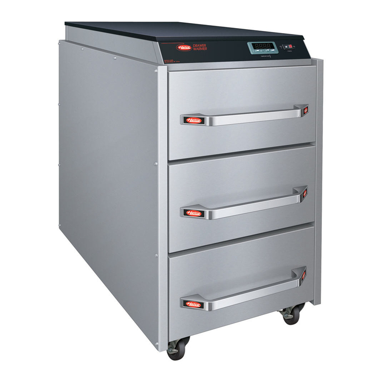
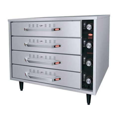
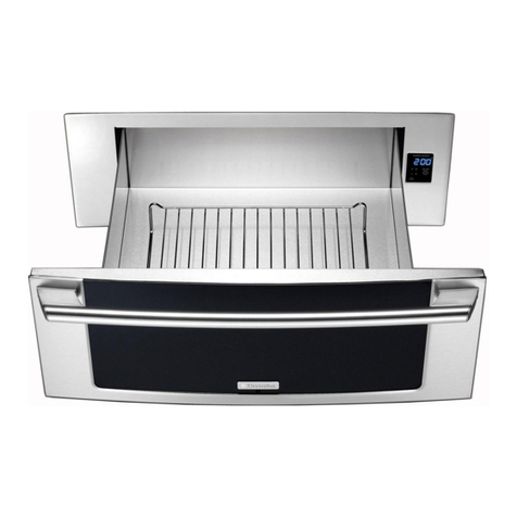
Hatco DRAWERMAX HDM-2 User manual

'468BC4AH>DAD=8C>=;8=4
See IMPORTANT OWNER INFORMATION
section for details.
DRAWER"-f
A0F4A,0A<4AB
"0=3"(4A84B
=BC0;;0C8>=0=3$?4A0C8=6"0=D0;
>A 0=3#>= ">34;B
I&W #07.05.235.00
© 2010 atco Corporation
Schuifverwarmers
Modelreeksen DM en DM-B
andleiding voor Installatie en Bediening
%
Cajones Térmicos
Series DM y DM-B
Manual de Instalación y Operación
%
Riscaldatori a cassetto
Serie DM, DM-B
Manuale per l'installazione e l'uso
%
eizladen
Serien DM und DM-B
Installations- und Bedienungshandbuch
%
Tiroirs chauffants
Séries DM et DM-B
Manuel d'installation et d'utilisation
%

Safety information that appears in this manual is identified by
the following signal word panels:
,'## 8=3820C4B 0 70I0A3>DB B8CD0C8>= F7827 85 =>C
0E>83432>D;3A4BD;C8=340C7>AB4A8>DB8=9DAH
*)$# 8=3820C4B 0 70I0A3>DB B8CD0C8>= F7827 85 =>C
0E>83432>D;3A4BD;C8=<8=>A>A<>34A0C48=9DAH
#$)8BDB43C>033A4BB?A02C824B=>CA4;0C43C>?4AB>=0;
8=9DAH
WARNING
NOTICE
CAUTION
#)'$*)$#
atco DRAWER"-f Drawer Warmers are designed to keep
foods at optimum serving temperatures without affecting quality.
They are built for tough kitchen duty with rugged stainless steel
construction, heavy-duty hardware, stainless steel slides, and
positive-closing drawers. DRAWER"- Drawer Warmers
keep everything from meat to vegetables to rolls hot and flavor-
fresh until served.
atco DRAWER"- Drawer Warmers are products of
extensive research and field testing. The materials used were
selected for maximum durability, attractive appearance, and
optimum performance. Every unit is inspected and tested
thoroughly prior to shipment.
This manual provides the installation, safety, and operating
instructions for DRAWER"- Drawer Warmers. atco
recommends all installation, operating, and safety instructions
appearing in this manual be read prior to installation or
operation of the unit.
<?>AC0=C$F=4A=5>A<0C8>=
=CA>3D2C8>=
<?>AC0=C(054CH=5>A<0C8>=
">34;4B2A8?C8>=
">34;4B86=0C8>=
(?4285820C8>=B
Plug Configurations .........................................................5
Electrical Rating Chart.....................................................5
Dimensions......................................................................5
=BC0;;0C8>=
General............................................................................6
Installing DM-2 Models .................................................6
Installing DM-2B Models...............................................7
$?4A0C8>=
General............................................................................8
Food olding Guide ........................................................8
"08=C4=0=24
General............................................................................9
Cleaning ..........................................................................9
$?C8>=B0=3224BB>A84B
)A>D1;4B7>>C8=6D834
=C4A=0C8>=0;!8<8C43,0AA0=CH
(4AE824=5>A<0C8>=
"%$')#)$,#'#$'")$#
Record the model number, serial number (located on the back
of the unit for free-standing units and on the inside of the left
panel for built-in units), voltage, and purchase date of the unit
in the spaces below. Please have this information available
when calling atco for service assistance.
Model No. ________________________________________
Serial No. ________________________________________
Voltage __________________________________________
Date of Purchase __________________________________
'468BC4AH>DAD=8C
Completing online warranty registration will prevent delay in
obtaining warranty coverage. Access the atco website at
FFF70C2>2>A?2><, select the Parts & Service pull-down
menu, and click on “Warranty Registration”.
Business 8:00 AM to 5:00 PM
ours: Central Standard Time (C.S.T.)
(Summer ours: June to September –
8:00 AM to 5:00 PM C.S.T.
Monday through Thursday
8:00 AM to 2:30 PM C.S.T. Friday)
Telephone: (414) 671-6350
E-mail: part[email protected]
Fax: (414) 671-3976 (Parts and Service)
Additional information can be found by visiting our web site at
FFF70C2>2>A?2><.
$#)#)(
2Form No. DMCEM-1010
"0:4BDA45>>3?A>3D2C70B144=740C43C>C74?A>?4A
5>>3B054C4<?4A0CDA4145>A4?;028=68=D=8C08;DA4C>740C
5>>3?A>3D2C?A>?4A;H<0HA4BD;C8=B4A8>DB740;C7A8B:B
)78BD=8C8B5>A7>;38=6?A4740C435>>3?A>3D2C>=;H
)78BD=8C8B=>C8=C4=3435>ADB41H278;3A4=>A?4AB>=B
F8C7 A43D243 ?7HB820; B4=B>AH >A <4=C0; 20?018;8C84B
=BDA4?A>?4ABD?4AE8B8>=>5278;3A4=0=3:44?C74<0F0H
5A><C74D=8C
"0:4BDA40;;>?4A0C>AB70E4144=8=BCAD2C43>=C74B054
0=3?A>?4ADB4>5C74D=8C
)78BD=8C<DBC14B4AE82431H@D0;85843?4AB>==4;>=;H
(4AE824 1H D=@D0;85843 ?4AB>==4; <0H ;403 C> 4;42CA82
B7>2:>A1DA=
)78B D=8C 70B => iDB4AB4AE82401;4j ?0ACB 5 B4AE824 8B
A4@D8A43>=C78BD=8C2>=C02C0=DC7>A8I430C2>(4AE824
64=C >A 2>=C02C C74 0C2> (4AE824 4?0AC<4=C 0C
50G
*'#/'
d (><44GC4A8>ABDA5024B>=C74D=8CF8;;64C7>C*B4
20DC8>=F74=C>D278=6C74B40A40B
d *B4 20DC8>= F74= >?4=8=6 3A0F4A >C 08A 4B20?4B
F74=3A0F4A8B>?4=
(C0=30A30=30??A>E43<0=D502CDA8=6>8;B<0HB<>:4D?
C><8=DC4B3DA8=68=8C80;BC0ACD?)78B8B0C4<?>A0AH
2>=38C8>=$?4A0C4D=8CF8C7>DC5>>3?A>3D2CD=C8;B<>:4
38BB8?0C4B
!>20C4 D=8C 8= 0= 0A40 C70C 8B 2>=E4=84=C 5>A DB4 )74
;>20C8>=B7>D;314;4E4;0=3BCA>=64=>D67C>BD??>ACC74
F4867C>5C74D=8C0=32>=C4=CB
>=>C;0HD=8C>=C745A>=C>A102:B8340<064C>C74
D=8C2>D;3>22DA
*B4=>=01A0B8E42;40=4AB>=;H1A0B8E42;40=4AB2>D;3
B2A0C27C7458=8B7>5C74D=8C<0AA8=68CB0??40A0=240=3
<0:8=68CBDB24?C81;4C>B>8;022D<D;0C8>=
WARNING
NOTICE
CAUTION
!)'($ /'
d %;D6D=8C8=C>0?A>?4A;H6A>D=3434;42CA820;A424?C02;4
>5C742>AA42CE>;C064B8I40=3?;D62>=586DA0C8>=5
?;D60=3A424?C02;43>=>C<0C272>=C02C0@D0;85843
4;42CA8280=C>34C4A<8=40=38=BC0;;C74?A>?4AE>;C064
0=3B8I44;42CA820;A424?C02;4
d )DA= ?>F4ABF8C27$ D=?;D6?>F4A 2>A3CDA= >55
?>F4A0C28A2D8C1A40:4A0=30;;>FD=8CC>2>>;145>A4
?4A5>A<8=60=H<08=C4=0=24>A2;40=8=6
d $#$)BD1<4A64>AB0CDA0C4F8C7F0C4A*=8C8B=>C
F0C4A?A>>5>=>C>?4A0C485D=8C70B144=BD1<4A643
>AB0CDA0C43F8C7F0C4A
d *=8C8B=>CF40C74A?A>>5!>20C4D=8C8=3>>ABF74A4
0<184=C08AC4<?4A0CDA48B0<8=8<D<>5cc
d >=>CBC40<2;40=>ADB44G24BB8E4F0C4A>=C74D=8C
d )78BD=8C8B=>Ci94C?A>>5j2>=BCAD2C8>=>=>CDB494C
2;40=B?A0HC>2;40=C78BD=8C
d >=>C?D;;D=8C1H?>F4A2>A3
d 8B2>=C8=D4DB485?>F4A2>A38B5A0H43>AF>A=
d >=>C0CC4<?CC>A4?08A>AA4?;024030<0643?>F4A
2>A3)742>A3<DBC14A4?;02431H0C2>0=DC7>A8I43
0C2> (4AE824 64=C >A 0 ?4AB>= F8C7 B8<8;0A
@D0;85820C8>=B
d >=>C2;40=D=8CF74=8C8B4=4A68I43>A7>C
d >=>C0;;>F;8@D83BC>B?8;;8=C>C74D=8C
d *B4 >=;H 4=D8=4 0C2> '4?;024<4=C %0ACB F74=
B4AE824 8B A4@D8A43 08;DA4 C> DB4 4=D8=4 0C2>
'4?;024<4=C %0ACB F8;; E>83 0;; F0AA0=C84B 0=3 <0H
BD1942C >?4A0C>AB >5 C74 4@D8?<4=C C> 70I0A3>DB
4;42CA820;E>;C064A4BD;C8=68=4;42CA820;B7>2:>A1DA=
4=D8=4 0C2> '4?;024<4=C %0ACB 0A4 B?4285843 C>
>?4A0C4B054;H8=C744=E8A>=<4=CB8=F7827C74H0A4
DB43(><405C4A<0A:4C>A64=4A82A4?;024<4=C?0ACB
3>=>C70E4C74270A02C4A8BC82BC70CF8;;0;;>FC74<C>
>?4A0C4B054;H8=0C2>4@D8?<4=C
'/'
d !>20C4D=8C0<8=8<D<>5<<r5A><2><1DBC81;4
F0;;B 0=3 <0C4A80;B 5 B054 38BC0=24B 0A4 =>C
<08=C08=4338B2>;>A0C8>=>A2><1DBC8>=2>D;3>22DA
d > =>C DB4 70AB7 274<820;B BD27 0B 1;4027 >A
2;40=4AB 2>=C08=8=6 1;4027 >E4= 2;40=4AB >A
5;0<<01;42;40=8=6B>;DC8>=BC>2;40=C78BD=8C
WARNING
'403C745>;;>F8=68<?>AC0=CB054CH8=5>A<0C8>=145>A4DB8=6C78B4@D8?<4=CC>0E>83B4A8>DB8=9DAH>A340C70=3
C>0E>8330<064C>4@D8?<4=C>A?A>?4ACH
"%$')#)().#$'")$#
3
Form No. DMCEM-1010
Form No. DMCEM-1010
4
"$!('%)$#
"$!(#)$#
;;">34;B
All atco DRAWER"-f Drawer Warmers are built of rugged
construction with durable nylon rollers, 12 gauge stainless steel
slides, and heavy-duty hardware. Each drawer features
adjustable drawer vents for humidity control, a POWER
ON/OFF switch, a TEMPERATURE control knob, and a
temperature gauge. Standard size pans 152 mm (6″) deep are
supplied with each drawer. The insulated top and sides provide
maximum energy efficiency and the heating elements are
warranted for two years. All DM Series models include an
attached 1829 mm (6′) power cord with plug.
">34;"
Model DM-2 is a two-drawer, free-standing unit. It is equipped
with 102 mm (4″) legs.
NOTE: Optional 76 mm (3″) casters are available. Refer to the
OPTIONS AND ACCESSORIES section for details.
Figure 1. Model DM-2
">34;"
Model DM-2B is two-drawer, built-in unit.
Figure 2. Model DM-2B
H D M - X B
Hatco
DRAWERMAX
Built-In
Quantity of Drawers
Figure 3. Model Designation

Form No. DMCEM-1010 5
(%)$#(
">34; +>;C064 ,0CCB <?B %;D6>=586DA0C8>= (78??8=6,4867C
DM-2 120 900 7.5 NEMA 5-15P 69 kg (152 lbs.)
230 (CE) 984 4.3 CEE 7/7 Schuko, BS-1336, or AS 3112 69 kg (152 lbs.)
DM-2B 120 900 7.5 NEMA 5-15P 65 kg (143 lbs.)
230 (CE) 984 4.3 CEE 7/7 Schuko, BS-1336, or AS 3112 65 kg (143 lbs.)
;42CA820;'0C8=670AC
%;D6>=586DA0C8>=B
Units are supplied from the factory with an electrical cord and
plug installed. Plugs are supplied according to the application.
!)' ($ /' %;D6 D=8C 8=C> 0 ?A>?4A;H
6A>D=3434;42CA820;A424?C02;4>5C742>AA42CE>;C064B8I4
0=3 ?;D6 2>=586DA0C8>= 5 ?;D6 0=3 A424?C02;4 3> =>C
<0C272>=C02C0@D0;858434;42CA8280= C> 34C4A<8=40=3
8=BC0;;C74?A>?4AE>;C0640=3B8I44;42CA820;A424?C02;4
NOTE: The specification label is located on the back of the unit
for free-standing units and on the inside of the left panel
for built-in units. See label for serial number and
verification of unit electrical information.
WARNING
Figure 4. Plug Configurations
NOTE: Receptacle not supplied by Hatco.
CEE 7/7 Schuko BS-1363
AS 3112
NEMA 5-15P
NOTE: Shipping weight includes packaging.
8<4=B8>=B
A B
D E
C
Front View Side View
Figure 5. DM-2 Dimensions
AB
F
CG
Front View Side View
Figure 6. DM-2B Dimensions
,83C7 4?C7 4867C >>C?A8=C >>C?A8=C D8;C= D8;C=
">34; ,83C7 4?C7 ,83C7 4867C
DM-2 749 mm 578 mm 614 mm 629 mm 484 mm --- ---
(29-1/2″) (22-3/4″) (24-3/16″) (24-3/4") (19-1/16") --- ---
DM-2B 743 mm 568 mm 512 mm --- --- 715 mm 483 mm
(29-1/4") (22-3/8") (20-3/16") --- --- (28-1/8") (19-1/16")
The shaded areas contain electrical information for =C4A=0C8>=0;<>34;B>=;H

4=4A0;
DRAWER"-f Drawer Warmers are shipped with most
components pre-assembled. Care should be taken when
unpacking the shipping carton to avoid damage to the unit and
components enclosed.
!)' ($ /' *=8C 8B =>C F40C74A?A>>5
!>20C4C74D=8C8=3>>ABF74A4C740<184=C08AC4<?4A0CDA4
8B0<8=8<D<>5cc
'/'!>20C4C74D=8C0<8=8<D<>5<<r
5A><2><1DBC81;4F0;;B0=3<0C4A80;B5B05438BC0=24B0A4
=>C<08=C08=432><1DBC8>=>A38B2>;>A0C8>=2>D;3>22DA
>=>C;0HD=8C>=C745A>=C>A102:B8340<064C>C74
D=8C2>D;3>22DA
1. Remove the unit from the carton.
2. Remove the information packet from the drawer of the unit.
NOTE: To prevent delay in obtaining warranty coverage,
complete online warranty registration. See the
IMPORTANT OWNER INFORMATION section for
details.
3. Remove tape and protective packaging from all surfaces of
unit.
4. Make sure the desired installation location is appropriate.
• Locate the unit in an area where the ambient air
temperature is constant and a minimum of 21°C (70°F).
Avoid areas that may be subject to active air movements
or currents (i.e., near exhaust fans/hoods and air
conditioning ducts).
• Make sure the unit is located on solid, level flooring or
in sturdy cabinetry.
• Make sure the unit is at the proper height in an area
convenient for use.
5. Install the unit. Refer to the appropriate installation
procedure in this section.
NOTICE
WARNING
=BC0;;8=6"">34;B
DM-2 models are freestanding units that require the
installation of 102 mm (4″) legs before operation.
1. Remove the plastic bag containing the four legs from the
drawer of the unit.
2. Remove any pans from the drawers and carefully lay the
unit on its side (requires two people).
3. Install each leg. and-tighten the legs until snug. Do not
over-tighten.
4. Return the unit to its upright position (requires two people).
If the unit is not level or rocks, turn the adjustable tip of the
appropriate leg to level the unit.
Figure 7. Leg Assembly
102 mm (4″) Leg
Lengthen
Shorten
Adjustable Tip
#()!!)$#
6Form No. DMCEM-1010

=BC0;;8=6"">34;B
DM-2B models are built-in units that require installation into a
cabinet before operation.
1. Cut the appropriate opening in the cabinet. Refer to the
illustration below for dimensions.
Figure 8. Cutout and Locking Strip Dimensions
NOTE: Maintain a minimum clearance of 25 mm (1") between
the cutout opening and the floor.
2. Fasten a locking strip (not supplied) to the lower front
inside lip of the cabinet opening.
3. Make sure a properly grounded electrical receptacle of the
correct voltage, size, and plug configuration is installed
inside the cabinet cutout. See the SPECIFICATIONS
section for details.
721 mm
(28-3/8″)
25 mm
(1″)
489 mm
(19-1/4″)
603 mm
(23-3/4″)
Front View Side View
22.2 mm
0.875″
3.2 mm
0.125″
Locking
Strip
Locking
Strip
4. Plug the power cord on the unit into the electrical
receptacle.
5. Partially insert the unit into the opening, making sure the
power cord is fed into the opening first.
6. Before installing the unit into the opening completely, apply
a bead of National Sanitation Foundation-approved sealant
between the drawer warmer flange and the cabinet facing.
7. Slide the unit into the opening until the front locking studs
drop behind the locking strip. To verify installation, pull out
bottom drawer completely and gently pull to ensure the unit
is locked in place.
Figure 9. Built-In Installation
Drawer
Warmer
Flange
Locking
Strip
Cabinet
Facing
Locking Studs
(underneath)
#()!!)$#
7
Form No. DMCEM-1010

4=4A0;
Use the following procedure to operate DRAWER"-f
Drawer Warmers. Each drawer can be controlled and
monitored individually using the adjustable drawer vents for
humidity control as well as the POWER ON/OFF switch,
TEMPERATURE control knob, and temperature gauge.
'403 0;; B054CH <4BB064B 8= C74 "%$')#) ().
#$'")$# B42C8>=145>A4>?4A0C8=6C78B4@D8?<4=C
(C0ACD?
1. For freestanding units, plug the unit into a properly grounded
electrical receptacle of the correct voltage, size, and plug
configuration. See the SPECIFICATIONS section for details.
2. Move the POWER ON/OFF (I/O) switch(es) to the ON (I)
position.
3. Turn the TEMPERATURE control knob(s) to the desired
setting(s). See the RECOMMENDED SETTINGS chart on
the control panel or the Food olding Guide in this section.
(C0=30A30=30??A>E43<0=D502CDA8=6>8;B<0HB<>:4D?
C><8=DC4B3DA8=68=8C80;BC0ACD?)78B8B0C4<?>A0AH
2>=38C8>=$?4A0C4D=8CF8C7>DC5>>3?A>3D2CD=C8;B<>:4
38BB8?0C4B
*'#/'
d (><44GC4A8>ABDA5024B>=C74D=8CF8;;64C7>C*B4
20DC8>=F74=C>D278=6C74B40A40B
d *B4 20DC8>= F74= >?4=8=6 3A0F4A >C 08A 4B20?4B
F74=3A0F4A8B>?4=
4. Allow unit 15–20 minutes to reach operating temperature.
5. Adjust the drawer vents for the desired humidity by sliding
the vent knob on the drawer front. Opening the vents all
the way allows maximum moisture to escape.
Figure 10. Drawer Vents
NOTE: Proper vent adjustment depends on the type and
amount of food held, as well as the frequency of drawer
opening.
(7DC3>F=
1. Move the POWER ON/OFF (I/O) switch(es) to the OFF (O)
position.
2. Allow the unit to cool before performing any cleaning or
maintenance.
Drawer Vents
Vent Knob
CAUTION
WARNING
Figure 11. DM-2 Control Panel
>>3>;38=6D834
'42><<4=343 )H?4>5 +4=C
%A>3D2C (C>A064)4<?4A0CDA4 40C (4CC8=6
Rolls, ard 71°–85°C (160°–185°F) Dry Open
Rolls, Soft 66°–79°C (150°–175°F) Moist Open– alf
Vegetables 79°–85°C (175°–185°F) Moist Open– alf
Meat, Poultry 74°–85°C (165°–185°F) Dry Open
Fish 74°–85°C (165°–185°F) Moist Closed
Casseroles 66°–79°C (150°–175°F) Dry Open
Pies, Desserts 71°–85°C (160°–185°F) Dry Open
Tacos, Tortillas 66°–71°C (150°–160°F) Moist Open– alf
>>3>;38=60?028CH
A standard drawer has the following capacity:
Dinner Rolls: 6–8 dozen
Ribs: 11–14 kg (25–30 lbs.)
Potatoes: 3–3-1/2 dozen
Upper Drawer
Controls
Lower Drawer
Controls
Temperature
Gauge
RECOMMENDED
SETTINGS Chart
TEMPERATURE
Control Knob
Power ON/OFF
(I/O) Switch
$%')$#
8Form No. DMCEM-1010

4=4A0;
DRAWER"- Drawer Warmers are designed for maximum
durability and performance with minimum maintenance.
!)'($ /'
d )DA=C74?>F4ABF8C27$D=?;D6C74?>F4A2>A30=3
0;;>F C74 D=8C C> 2>>; 145>A4 ?4A5>A<8=6 0=H
<08=C4=0=24>A2;40=8=6
d $#$)BD1<4A64>AB0CDA0C4F8C7F0C4A*=8C8B=>C
F0C4A?A>>5>=>C>?4A0C485D=8C70B144=BD1<4A643
>AB0CDA0C43F8C7F0C4A
d >=>CBC40<2;40=>ADB44G24BB8E4F0C4A>=C74D=8C
d )78BD=8C8B=>Ci94C?A>>5j2>=BCAD2C8>=>=>CDB494C
2;40=B?A0HC>2;40=C78BD=8C
d >=>C2;40=C74D=8CF74=8C8B4=4A68I43>A7>C
)78B D=8C 70B => iDB4AB4AE82401;4j ?0ACB 5 B4AE824 8B
A4@D8A43>=C78BD=8C2>=C02C0=DC7>A8I430C2>(4AE824
64=C>A2>=C02CC740C2>(4AE8244?0AC<4=C0C
50G
WARNING
;40=8=6
To preserve the finish of the unit as well as maintain
performance, it is recommended that the unit be cleaned daily.
1. Turn off the unit, unplug the power cord (freestanding
models), and allow the unit to cool.
2. Remove and wash all food pans and accessories.
*B4=>=01A0B8E42;40=4AB>=;H1A0B8E42;40=4AB2>D;3
B2A0C27C7458=8B7>5C74D=8C<0AA8=68CB0??40A0=240=3
<0:8=68CBDB24?C81;4C>B>8;022D<D;0C8>=
3. Wipe down surfaces using a damp cloth. A non-abrasive,
cream cleaner may be used for difficult stains.
• Make sure to check and clean the interior of the unit.
Food pieces may fall from the food pans into the drawer
cavity. *)$# DA= 0I0A3 h > =>C 2;40=
3A0F4A20E8CHF74=D=8C8B>=>A?;D66438=
NOTICE
"#)##
9
Form No. DMCEM-1010
<<r0BC4AB
76 mm (3″) casters are available for the freestanding unit in
place of the legs. Use the following procedure to install casters
onto the bottom of the unit.
>=>C;0HD=8C>=C745A>=C>A102:B834>A30<064C>C74
D=8C2>D;3>22DA
1. Remove any pans from the drawers of the unit.
2. Carefully lay the unit on its left or right side (requires two
people).
3. Remove the legs, if installed.
4. Place a washer (supplied with casters) over the threaded
stud on the caster.
NOTICE
$%)$#(#(($'(
5. Install the caster with washer into a hole where a leg was
removed. Tighten securely.
Figure 12. Installing Casters
6. Repeat steps 3 and 4 for the remaining three casters.
7. Return the unit to the upright position (requires two
people).
76 mm (3″) Caster
Washer

(H<?C>< %A>101;40DB4 >AA42C8E42C8>=
Unit too hot. TEMPERATURE control knob set too high. Move TEMPERATURE control knob to a lower
setting.
Unit plugged into incorrect power supply. Verify with qualified personnel that power supply
matches unit specification.
Internal thermostat defective. Contact Authorized Service Agent or atco for
assistance.
Unit not hot enough. Unit not allowed enough time to preheat. Allow unit 15–20 minutes to reach operating
temperature.
TEMPERATURE control knob set too low. Move TEMPERATURE control knob to a higher
setting.
Drawer(s) not closed completely. Make sure all drawers are closed completely.
Internal thermostat defective. Contact Authorized Service Agent or atco for
assistance.
Product too dry. Drawer vent in open position. Move drawer vent to closed position.
Product too moist. Drawer vent in closed position. Move drawer vent to open position
Unit not working at all. Unit not plugged in. Plug unit into proper power supply.
Unit not turned on. Move POWER ON/OFF switch to the ON
position.
Circuit breaker tripped. Reset circuit breaker.
POWER ON/OFF switch defective. Contact Authorized Service Agent or atco for
assistance.
Internal thermostat defective. Contact Authorized Service Agent or atco for
assistance.
eating element burned out. Contact Authorized Service Agent or atco for
assistance.
)78BD=8C<DBC14B4AE82431H@D0;85843?4AB>==4;>=;H
(4AE824 1H D=@D0;85843 ?4AB>==4; <0H ;403 C> 4;42CA82
B7>2:>A1DA=
WARNING
!)' ($ /' )DA= ?>F4A BF8C27 $
D=?;D6 ?>F4A 2>A3 0=3 0;;>F D=8C C> 2>>; 145>A4
?4A5>A<8=60=H<08=C4=0=24>A2;40=8=6
WARNING
)'$*!($$)#*
10 Form No. DMCEM-1010

Form No. DMCEM-1010 11
#)'#)$#!!"),''#).
%'$*),''#).
atco warrants the products that it manufactures (the
“Products”) to be free from defects in materials and
workmanship, under normal use and service, for a period of
one (1) year from the date of purchase when installed and
maintained in accordance with atco’s written instructions or
18 months from the date of shipment from atco. Buyer must
establish the Product’s purchase date by means satisfactory to
atco in its sole discretion.
atco warrants the following Product components to be free
from defects in materials and workmanship from the date of
purchase (subject to the foregoing conditions) for the period(s)
of time and on the conditions listed below:
0 )F>.40A%0ACB,0AA0=CH
Conveyor Toaster Elements (metal sheathed)
Drawer Warmer Elements (metal sheathed)
Drawer Warmer Drawer Rollers and Slides
Food Warmer Elements (metal sheathed)
Display Warmer Elements (metal sheathed air heating)
olding Cabinet Elements (metal sheathed air heating)
Built-In eated Well Elements — WB and WBI Series
(metal sheathed)
1 $=4.40A%0ACB%!*(>DA.40AB%0ACB
,0AA0=CH>=?A>A0C43C4A<BC70C0C2>F8;;4G?;08=
0CDH4AkBA4@D4BC
3CS and FR Tanks
2 )4=.40A%0ACB,0AA0=CH
Electric Booster eater Tanks
Gas Booster eater Tanks
3 #8=4CH0H%0ACB,0AA0=CH
Replacement Parts
T E FOREGOING WARRANTIES ARE EXCLUSIVE AND IN
LIEU OF ANY OT ER WARRANTY, EXPRESSED OR
IMPLIED, INCLUDING BUT NOT LIMITED TO ANY IMPLIED
WARRANTY OF MERC ANTABILITY OR FITNESS FOR A
PARTICULAR PURPOSE OR PATENT OR OT ER
INTELLECTUAL PROPERTY RIG T INFRINGEMENT.
Without limiting the generality of the foregoing, SUC
WARRANTIES DO NOT COVER: Coated incandescent light
bulbs, fluorescent lights, heat lamp bulbs, coated halogen light
bulbs, halogen heat lamp bulbs, glass components, and fuses;
Product failure in booster tank, fin tube heat exchanger, or other
water heating equipment caused by liming, sediment buildup,
chemical attack, or freezing; or Product misuse, tampering or
misapplication, improper installation, or application of improper
voltage.
!"))$#$'"(#"(
atco’s liability and Buyer’s exclusive remedy hereunder will be
limited solely to replacement of part or Product using, at atco’s
option, new or refurbished parts or Product by atco or a atco-
authorized service agency with respect to any claim made
within the applicable warranty period referred to above. atco
reserves the right to accept or reject any such claim in whole or
in part. In the context of this Limited Warranty, “refurbished”
means a part or Product that has been returned to its original
specifications by atco or a atco-authorized service agency.
atco will not accept the return of any Product without prior
written approval from atco, and all such approved returns shall
be made at Buyer’s sole expense. ATCO WILL NOT BE
LIABLE, UNDER ANY CIRCUMSTANCES, FOR
CONSEQUENTIAL OR INCIDENTAL DAMAGES, INCLUDING
BUT NOT LIMITED TO LABOR COSTS OR LOST PROFITS
RESULTING FROM T E USE OF OR INABILITY TO USE T E
PRODUCTS OR FROM T E PRODUCTS BEING
INCORPORATED IN OR BECOMING A COMPONENT OF
ANY OT ER PRODUCT OR GOODS.
('+#$'")$#
The warranty on atco DRAWER"-f Drawer Warmers is
for one year from date of purchase or eighteen months from
date of shipping from atco, whichever occurs first.
If you experience a problem with a Drawer Warmer during the
warranty period, please do the following:
>=C02C!>20;0C2>40;4A
When contacting the atco dealer for service assistance,
please supply the dealer with the following information to
ensure prompt processing:
• Model of unit
• Serial number
• Specific problem with the unit
• Date of purchase
• Name of business
• Shipping address
• Contact name and phone number
The atco dealer will do the following:
• Provide replacement part(s) as required
• Submit warranty claim to atco for processing
#>=,0AA0=CH%A>1;4<B
If you experience a non-warranty problem that requires
assistance, please contact the nearest Authorized atco
Service Agency.
To locate the nearest Service Agency:
• access our website at FFF70C2>2>A?2><, select the
Resources pull-down menu, and click on “Find Service
Agent/Distributor”
• call atco Service at 414-671-6350
• e-mail atco Service at partsandservice@hatcocorp.com

Form-Nr. DMCEM-1010
12
#!)
Sicherheitshinweise sind in diesem andbuch durch ein
Warnsymbol mit den folgenden Signalwörtern gekennzeichnet:
,'#*# 1434DC4C 30BB 48=4 4507A B27F4A4A >34A
C^3;8274A+4A;4CID=64=14BC47CF4==384(8CD0C8>==827C
E4A<8434=F8A3
+$'() 1434DC4C 30BB 48=4 4507A ;4827C4A >34A
<8CC4;B27F4A4A+4A;4CID=64=14BC47CF4==384(8CD0C8>=
=827CE4A<8434=F8A3
#,( 1434DC4C 30BB 48=4 4507A E>= 4AQC4 >34A
(027B27Q34=14BC47C
HINWEIS
VORSICHT
WARNUNG
#!)*#
atco DRAWER"-f eizladen sind zum Warmhalten von
Speisen bei optimaler Serviertemperatur ohne
Qualitätseinbußen vorgesehen. Sie sind für anspruchsvollen
Kücheneinsatz als robuste Edelstahlkonstruktion, mit robusten
Befestigungselementen, Gleitbahnen aus Edelstahl und als
bündig schließende Laden ausgeführt. DRAWER"-
eizladen halten Fleisch und Gemüse, aber auch Brötchen bis
zum Servieren warm und frisch.
atco DRAWER"- eizladen basieren auf umfangreicher
Forschung und praktischen Tests. Die verwendeten Werkstoffe
wurden gewählt, um optimale Dauerhaftigkeit, attraktives
Aussehen und optimale Leistung zu gewährleisten. Jedes
Gerät wird vor der Auslieferung gründlich inspiziert und
getestet.
Dieses andbuch enthält die Einbau-, Sicherheits- und
Betriebsanweisungen für die DRAWER"- eizladen. atco
empfiehlt, alle in diesem andbuch enthaltenen Einbau-,
Sicherheits- und Bedienungsanweisungen vor der Installation
und Inbetriebnahme zu lesen.
,827C864=5>A<0C8>=4=5bA34=4=DCI4A
8=;48CD=6
,827C864(8274A748CB78=F48B4
">34;;14B27A481D=6
">34;;14I4827=D=6
)427=8B2740C4=
Steckerkonfigurationen ..................................................15
Tabelle der elektrischen Anschlüsse .............................15
Abmessungen ...............................................................15
D5BC4;;4=34B4AQC
Allgemeines ...................................................................16
Einbau der Modelle DM-2 ...........................................16
Einbau der Modelle DM-2B.........................................17
4CA841
Allgemeines ...................................................................18
Leitfaden zum Warmhalten von Speisen.......................18
,0ACD=6
Allgemeines ...................................................................
Reinigung ......................................................................
$?C8>=4=D=3/D147^A
'827C;8=84=IDA(C^AD=6B14B48C86D=6
8=F48B4IDA0A0=C84;48BCD=6
=C4A=0C8>=0;44B27AQ=:C40A0=C84
,)#$'")$##N'##*)/'
Schreiben Sie die Modellbezeichnung, die Seriennummer
(befindet sich bei freistehenden Geräten auf der Rückseite und
bei Einbaugeräten an der Innenseite der linken Abdeckung),
die Spannung und das Kaufdatum in die folgenden Zeilen.
aben Sie bitte dies Information zur and, wenn Sie atco
wegen einer Service-Unterstützung anrufen.
Modellbezeichnung ____________________________
Seriennummer ________________________________
Spannung ____________________________________
Kaufdatum ____________________________________
'468BCA84A4=(847A4AQC
Wenn Sie die Online-Garantieregistrierung ausfüllen,
vermeidet das Verzögerungen beim Erhalt der
Garantiedeckung. Rufen Sie die atco Website unter
FFF70C2>2>A?2>< auf, wählen Sie das Pulldown-Menü
„Parts & Service“ (Ersatzteile und Wartung) aus und klicken
Sie auf „Warranty Registration“ (Garantieregisrtierung).
Geschäftszeiten:
8.00 Uhr bis 17.00 Uhr
Central Standard Time (CST)
(im Sommer: Juni bis September –
8.00 Uhr bis 17.00 Uhr (CST)
Montag bis Donnerstag
8.00 Uhr bis 14.30 Uhr (CST) Freitag)
Telefon: (414) 671-6350
E-mail: part[email protected]
Fax: (414) 671-3976 (Ersatzteile und Service)
Weitere Informationen finden Sie auf unserer Website unter
FFF70C2>2>A?2><.

Form-Nr. DMCEM-1010 13
,)(')(#,(
(8274ABC4;;4= 30BB 30B #07AD=6B<8CC4;?A>3D:C 0D5 384
:>AA4:C4)4<?4A0CDA5bAB8274A4= >=BD<4AFQA<CFDA34
14E>A4B8=34=,QA<4A64BC4;;CF8A3,4==384(?48B4=
=827C :>AA4:C 4AFQA<C F4A34= 14BC474= B27F4A4
4BD=3748CBA8B8:4=84B4B4AQC384=C=DAID<0;C4=E>=
E>A64FQA<C4=(?48B4?A>3D:C4=
84B4B4AQC8BC=827C5bA34=41A0D273DA27 8=34A>34A
%4AB>=4=<8C48=64B27AQ=:C4=:^A?4A;8274=B4=B>A8B274=
>34A 648BC864= Q786:48C4= E>A64B474= bA 48=4
>A3=D=6B64<Qe4 40D5B827C86D=6 E>= 8=34A= B>A64=
D=3384B4E>=34<4AQC54A=70;C4=
(8274ABC4;;4= 30BB 0;;4 4384=4A 8< B8274A4= D=3
502764A427C4=41A0D2734B4AQCB64B27D;CB8=3
'4?0A0CDA4=0<30B4AQC3bA54==DAE>=@D0;858I84AC4<
%4AB>=0; 3DA27645b7AC F4A34= +>= D=@D0;858I84AC4<
%4AB>=0; 3DA27645b7AC4 '4?0A0CDA4= :^==4= ID
;4:CA>B27>2:B>34A+4A1A4==D=64=5b7A4=
0;;B48=4'4?0A0CDA384B4B4AQCB4A5>A34A;827B48=B>;;C4
F4=34= (84 B827 0= 7A4= 0DC>A8B84AC4= 0C2>
(4AE82414CA841>34A0=3840C2>(4AE82401C48;D=6D=C4A
)4;45>=>34A0G
+''##*#('
d 8=864De4=5;Q274= 34B 4AQCB F4A34= 748e 48<
4Ab7A4=384B4A;Q274=+>AB827CF0;C4=;0BB4=
d 48< M55=4= 34A !034 E>AB827C86 B48= DB 34A
64^55=4C4=!0344=CF4827C748e4!D5C
(C0=30A3<Qe864D=3ID64;0BB4=44AC86D=6B^;4A0D274=
14834A0=5Q=6;8274==14CA841=07<4 18BID"8=DC4=
;0=6 0B 8BC 48= E>Ab14A6474=34A /DBC0=3 /DA
4FQ7A;48BCD=6 34B B8274A4= 4CA841B <DBB 30B 4AQC
B>;0=64>7=4(?48B4=14CA8414=F4A34=18B:48='0D27
<47A4=CBC47C
(C4;;4= (84 30B 4AQC D=C4A 8=70;CD=6 34A A827C864=
)74:4=7^74 0= 48=4A 64486=4C4= (C4;;4 0D5 4A
D5BC4;;D=6B>AC B>;;C4 414= B48= D< E4AB474=C;8274B
*<:8??4= 34B 4AQCB 1IF 4A0DB50;;4= 34B =70;CB ID
E4A78=34A= D=3 BC0=354BC 64=D6 D< 30B 4F827C E>=
4AQCD=3(?48B4=IDCA064=
0B 4AQC =827C 0D5 384 +>A34A >34A 'b2:B48C4 ;464=
03DA27:^==C430B4AQC14B27Q386CF4A34=
+4AF4=34= (84 =DA =827CB274D4A=34 '48=86D=6B<8CC4;
(274D4A=34'48=86D=6B<8CC4;:^==4=384$14A5;Q27434B
4AQCBE4A:A0CI4=D=34B30<8CD=0=B47=;827D=30=5Q;;86
5bA30B4BCB4CI4=E>=+4AD=A48=86D=64=<0274=
HINWEIS
VORSICHT
WARNUNG
'+$#! )'$($ (
d 0B 4AQC <DBB 0= 48=4 >A3=D=6B64<Qe 644A34C4
(C42:3>B4 <8C 34A A827C864= (?0==D=6 A^e4 D=3
(C42:4A:>=586DA0C8>= 0=64B27;>BB4= F4A34= ,4==
(C42:4AD=3(C42:3>B4=827Cb14A48=BC8<<4=F4=34=
(84 B827 0= 48=4= @D0;858I84AC4= ;4:CA8:4A D< 384
A827C864#4CIB?0==D=6D=3(C42:4A0ACID4A<8CC4;=D=3
384:>AA4:C4(C42:3>B4ID8=BC0;;84A4=
d 4= #4CIB270;C4A *((!)# 30B #4CI:014;
01I8474=384 (?0==D=6BE4AB>A6D=6 0< )A4==B270;C4A
D=C41A4274= D=3 30B 4AQC 01:b7;4= ;0BB4= 14E>A
,0ACD=6B>34A'48=86D=6B0A148C4=3DA27645b7ACF4A34=
d )0D274=(8430B4AQC#)8=,0BB4AD=3A48=864=
(8430B4AQC#)<8Cb14A<Qe86E84;,0BB4A0B
4AQC 8BC =827C F0BB4A3827C B 30A5 =827C 14CA8414=
F4A34= F4== 4B 8= ,0BB4A 64C0D27C >34A <8C
b14A<Qe86E84;,0BB4A64A48=86CFDA34
d 0B4AQC8BC=827CF8CC4AD=6B54BC(C4;;4=(8430B4AQC
8= 48=4< '0D< 0= 48=4A (C4;;4 0D5 0= 34A 384
*<641D=6BC4<?4A0CDA<8=34BC4=Bc14CAQ6C
d '48=864=(8430B4AQC=827C<8C0<?5>34Ab14A<Qe86
E84;,0BB4A
d 84B4B4AQC8BC=827C5bA38A4:C4B1B?Ab74=<8C48=4<
,0BB4ABCA07; 64486=4C B 30A5 =827C <8C 48=4<
(?Ab7BCA07;64A48=86CF4A34=
d /8474=(8430B4AQC=827C0< 014;
d 4CA4814= (84 30B 4AQC =827C F4== 30B #4CI:014;
3DA2764B274D4AC>34A0164=DCIC8BC
d +4ABD274=(84 =827C48=14B27Q386C4B#4CI:014;ID
A4?0A84A4=>34AID4AB4CI4=0B 014;<DBB3DA27
0C2>48=4=0DC>A8B84AC4=(4AE82414CA841>34A48=4=
@D0;858I84AC4=)427=8:4A4AB4CICF4A34=
d '48=864=(8430B4AQC=827CF4==4BB8278=4CA841
1458=34C>34A748e8BC
d 27C4= (84 30A0D5 30BB :48=4 ;bBB86:48C4= 8= 30B
4AQC64B27bCC4CF4A34=
d +4AF4=34=(8414834A'4?0A0CDAE>=0C2>4AQC4=
0DBB27;84e;827 0C2> AB0CIC48;4 ,4== (84 :48=4
$A868=0;0C2>AB0CIC48;4 E4AF4=34= F4A34= 0;;4
0A0=C84=D=6b;C86 D=3 (84 B4CI4=3844384=4A34A
4AQC4 <^6;8274AF48B4 645Q7A;8274= 4;4:CA8B274=
(?0==D=64= 0DB F4;274 ID (CA><B27;06 >34A
+4A1A4==D=64= 5b7A4= :^==4= $A868=0;0C2>
AB0CIC48;4 B8=3 5bA 34= B8274A4= 4CA841 D=C4A 34=
646414=4= 8=B0CI1438=6D=64= 0DB64;46C "0=274
AB0CIC48;4 0=34A4A 4ABC4;;4A >34A #02710DC48;4
E4A5b64==827Cb14A384645>A34AC4=864=B2705C4=D=3
5D=:C8>=84A4==827CB8274A8=0C2>4AQC4=
'#'
d (C4;;4=(8430B4AQC<8C<8=34BC4=B<<1BC0=3ID
4=C5;0<<10A4= ,Q=34= >34A "0C4A80;4= 0D5 ,4==
384B4A (8274A748CB01BC0=3 =827C 48=6470;C4= F8A3
:^==4=+4A5QA1D=64=4=CBC474=D=31A4==10A4(C>554
:^==4=B8274=CIb=34=
d 48=4 066A4BB8E4= 74<8:0;84= >34A '48=864A <8C
;4827<8CC4; $54=A48=864A >34A 1A4==10A4
'48=86D=6B;^BD=64= ID< '48=864= 384B4B 4AQCB
14=DCI4=
WARNUNG
+>A34A=F4=3D=6384B4ADBAbBCD=6;4B4=(843845>;64=34=F827C864=(8274A748CB8=5>A<0C8>=4=D<4A=BC4
+4A;4CID=6>34A)>3IDE4A<4834=D=3(27034=34ADBAbBCD=6>34A34B864=CD<BIDE4A<4834=

Form-Nr. DMCEM-1010
14
"$!!('*#
;;4">34;;4
Alle atco DRAWER"-f eizladen haben eine robuste
Konstruktion mit langlebigen Nylonrollen, Gleitschienen der
Stärke "Gauge 12" und robuste Befestigungselemente. Jede
Lade ist mit verstellbaren Entlüftungsschlitzen zur
Feuchtigkeitsregelung, einem EIN/AUS-Netzschalter (I/O),
einem TEMPERATUR-Regelknopf und einer
Temperaturanzeige ausgestattet. Mit jeder Lade werden
Wannen in Standardgröße, 152 mm (6″) tief, mitgeliefert. Die
isolierte Oberseite und Seitenwände bieten maximale
Energieeffizienz und die eizelemente sind durch eine
Zweijahresgarantie gedeckt. Alle Modelle der DM-Serie sind
mit einem befestigten, 1829 mm (6′) langen Netzkabel mit
Stecker ausgestattet.
">34;;"
Modell DM-2 ist ein freistehendes Gerät mit zwei Laden. Es
ist mit 102 mm (4″) Standbeinen versehen.
ANMERKUNG : Optionale 76 mm (3″) Laufrollen sind
verfügbar. Für Details siehe Abschnitt
OPTIONEN UND ZUBEHÖR.
Abbildung 1. Modell DM-2
">34;;"
Modell DM-2B ist ein Einbaumodell mit zwei Laden.
Abbildung 2. Modell DM-2B
"$!!/#*#
H D M - X B
Hatco
DRAWERMAX
Einbaumodell
Anzahl der Laden
Abbildung 3. Modellbezeichnung

Form-Nr. DMCEM-1010 15
)#()#
)014;;44A;4:CA8B274==B27;bBB4
(C42:4A:>=586DA0C8>=4=
Geräte werden werkseitig mit einem Netzkabel mit
angebrachtem Stecker ausgerüstet. Die gelieferten Stecker
entsprechen der jeweiligen Anwendung.
'+$#! )'$($ (0B4AQC<DBB0=
48=4>A3=D=6B64<Qe644A34C4(C42:3>B4<8C34AA827C864=
(?0==D=6 A^e4 D=3 (C42:4A:>=586DA0C8>=
0=64B27;>BB4= F4A34= ,4== (C42:4A D=3 (C42:3>B4
=827C b14A48=BC8<<4= F4=34= (84 B827 0= 48=4=
@D0;858I84AC4=;4:CA8:4AD<384A827C864#4CIB?0==D=6D=3
(C42:4A0AC ID 4A<8CC4;= D=3 384 :>AA4:C4 (C42:3>B4 ID
8=BC0;;84A4=
ANMERKUNG: Die Steckdose wird nicht von Hatco
bereitgestellt.
WARNUNG
ANMERKUNG : Das Typenschild befindet sich auf der
Rückseite von freistehenden Geräten und
bei Einbaumodellen an der Innenseite der
linken Seitenwand. Das Typenschild enthält
die Seriennummer und alle Daten zum
Überprüfen der elektrischen Informationen.
Abbildung 4. Steckerkonfigurationen
CEE 7/7 Schuko BS-1363
AS 3112
NEMA 5-15P
Die elektrischen Daten in den schattierten Feldern betreffen nur =C4A=0C8>=0;4<>34;;4.
ANMERKUNG : Das Versandgewicht ist einschließlich Verpackung angegeben.
">34;; (?0==D=6 ,0CCB <?4A4 (C42:4A:>=586DA0C8>= +4AB0=364F827C
DM-2 120 900 7.5 NEMA 5-15P 69 kg (152 lbs.)
230 (CE) 984 4.3 CEE 7/7 Schuko, BS-1336, AS 3112 69 kg (152 lbs.)
DM-2B 120 900 7.5 NEMA 5-15P 65 kg (143 lbs.)
230 (CE) 984 4.3 CEE 7/7 Schuko, BS-1336, AS 3112 65 kg (143 lbs.)
1<4BBD=64=
A B
D E
C
Vorderansicht Seitenansicht
Abbildung 5. Abmessungen DM-2
AB
F
CG
Vorderansicht Seitenansicht
Abbildung 6. Abmessungen DM-2B
A48C4 )8454 ^74 A48C4IF8B274= )8454IF8B274= A48C4 ^74
">34;; be4= be4= 8=10D<>34;; 8=10D<>34;;
DM-2 749 mm 578 mm 614 mm 629 mm 484 mm --- ---
(29-1/2″) (22-3/4″) (24-3/16″) (24-3/4") (19-1/16") --- ---
DM-2B 743 mm 568 mm 512 mm --- --- 715 mm 483 mm
(29-1/4") (22-3/8") (20-3/16") --- --- (28-1/8") (19-1/16")

Form-Nr. DMCEM-1010
16
*()!!#('J)(
;;64<48=4B
DRAWER"-f eizladen werden mit den meisten
Komponenten zusammengebaut ausgeliefert. Beim Auspacken
des Versandkartons darauf achten, um Schäden am Gerät und
den beiliegenden Komponenten zu verhüten.
'+$#! )'$($ (0B4AQC8BC=827C
F8CC4AD=6B54BC(C4;;4=(8430B4AQC8=48=4<'0D<0=
48=4A (C4;;4 0D5 0= 34A 384 *<641D=6BC4<?4A0CDA
<8=34BC4=Bc14CAQ6C
'#'(C4;;4=(8430B4AQC<8C<8=34BC4=B
<<1BC0=3ID4=C5;0<<10A4=,Q=34=>34A"0C4A80;4=
0D5 ,4== 384B4A (8274A748CB01BC0=3 =827C 48=6470;C4=
F8A3 :^==4= +4A5QA1D=64= 4=CBC474= D=3 1A4==10A4
(C>554:^==4=B8274=CIb=34=
0B 4AQC =827C 0D5 384 +>A34A >34A 'b2:B48C4 ;464=
03DA27:^==C430B4AQC14B27Q386CF4A34=
1. Nehmen Sie das Gerät aus dem Versandbehälter.
2. Das Informationspaket aus der Lade nehmen.
ANMERKUNG : Um Verzögerungen beim Garantiebeginn
zu vermeiden, führen Sie die Online-
Garantieregistrierung bitte sofort durch.
Einzelheiten dazu finden Sie unter
WICHTIGE INFORMATIONEN.
3. Entfernen Sie Klebeband und Schutzfolien von allen
Oberflächen des Geräts.
4. Stellen Sie das Gerät am gewünschten Ort auf.
• Das Gerät in einem Bereich mit konstanter
Umgebungslufttemperatur (mindestens 21°C [70°F])
anbringen. Bereiche, die aktiven Luftbewegungen oder
-strömen ausgesetzt sind (z. B. in der Nähe von
Gebläsen/Lüftern und Klimatisierungsrohren) sind zu
meiden.
• Achten Sie darauf, dass das Gerät auf einem stabilen,
waagrechten Boden oder in ausreichend starken
Schränken aufgestellt wird.
• Wählen Sie einen Ort mit der richtigen Thekenhöhe und
bequemem Zugang.
5. Das Gerät einbauen. Dazu auf das entsprechende
Einbauverfahren in diesem Abschnitt Bezug nehmen.
HINWEIS
WARNUNG
8=10D34A">34;;4"-
DM-2 Modelle sind freistehende Geräte, bei denen vor der
Inbetriebnahme die 102 mm (4″) Standbeine angebracht
werden müssen.
1. Den Kunststoffbeutel mit den vier Standbeinen aus der
Lade nehmen.
2. Das Gerät behutsam auf die Seite kippen (dazu sind zwei
Personen erforderlich)
. 3. Die einzelnen Standbeine einbauen. Die Standbeine von
and festziehen. Nicht zu stark festziehen.
4. Das Gerät wieder aufrecht stellen (dazu sind zwei
Personen erforderlich). Wenn das Gerät nicht nivelliert ist
oder wackelt, die verstellbare Spitze des entsprechenden
Standbeins verdrehen, bis das Gerät nivelliert ist.
Abbildung 7. Einbau der Standbeine
102 mm (4”) Standbein
Verlängern
Verkürzen
Verstellbare
Spitze

Form-Nr. DMCEM-1010 17
*()!!#('J)(
8=10D34A">34;;4"-
DM-2B Modelle sind Einbaugeräte, die vor der
Inbetriebnahme in einen Schrank eingebaut werden müssen.
1. Eine dementsprechende Öffnung in den Schrank
schneiden. Bezugsmaße sind der Abbildung unten zu
entnehmen.
Abbildung 8. Bezugsmaße von Ausschnitt und Sicherungsleiste
ANMERKUNG : Einen Mindestfreiraum von 25 mm (1")
zwischen der Ausschnittsöffnung und dem
Boden beibehalten.
2. Eine Sicherungsleiste (nicht mitgeliefert) an der Innenseite
der unteren Vorderkante in der Schranköffnung befestigen.
3. Sicherstellen, dass in der Schranköffnung eine
Schukosteckdose mit korrekter Spannung, Größe und
Bauart vorgesehen wird. Einzelheiten sind dem Abschnitt
TEC NISC E DATEN zu entnehmen.
4. Das Netzteil des Geräts an die Steckdose anschließen.
5. Das Gerät teilweise in die Öffnung schieben; dabei darauf
achten, dass das Netzkabel als erstes in die Öffnung
eingeführt wird.
721 mm
(28-3/8″)
25 mm
(1″)
489 mm
(19-1/4″)
603 mm
(23-3/4″)
Vorderansicht Seitenansicht
22.2 mm
0.875″
3.2 mm
0.125″
Sicherungsleiste
6. Vor dem vollständigen Einbau des Geräts in die Öffnung
einen Wulst Dichtmittel (mit Zulassung nach National
Sanitation Foundation) zwischen den eizladenflansch und
die Schrankstirnseite auftragen.
7. Das Gerät in die Öffnung schieben, bis die vorderen
Arretierzapfen hinter der Sicherungsleiste nach unten
fallen. Zur Überprüfung des Einbaus die untere Lade
komplett herausziehen und sacht weiter ziehen, um
sicherzustellen, dass sie arretiert ist.
Abbildung 9. Anbringen des Einbaumodells
Heizladenflansch
Sicherungsleiste
Schrank-
Stirnseite
Arretierzapfen (darunter)

Form-Nr. DMCEM-1010
18
)'
;;64<48=4B
Die DRAWER"-f eizladen dem folgenden Verfahren
gemäß betreiben. Jede Lade kann mit den verstellbaren
Schlitzen zur Feuchtigkeitsregelung sowie dem EIN/AUS-
Netzschalter (I/O), dem TEMPERATUR-Regelknopf und der
Temperaturanzeige einzeln gesteuert und überwacht werden.
!4B4=(840;;4(8274A748CB78=F48B48<1B27=8CC ,)
(')(#,(14E>A(8430B4AQCE4AF4=34=
=14CA841=07<4
1. Das freistehende Gerät an eine geerdete Steckdose mit
korrekter Spannungsversorgung und passender
Ausführung anschließen. Einzelheiten sind dem Abschnitt
TEC NISC E DATEN zu entnehmen.
2. Den EIN/AUS-Netzschalter (I/0) auf EIN (I) stellen.
3. Den/die TEMPERATUR-Regelknöpfe auf die gewünschten
Werte einstellen. Siehe dazu die Tabelle mit den
empfohlenen Einstellungen oder den Leitfaden zum
Warmhalten von Speisen in diesem Abschnitt.
(C0=30A3<Qe864D=3ID64;0BB4=44AC86D=6B^;4A0D274=
14834A0=5Q=6;8274==14CA841=07<418BID"8=DC4=
;0=6 0B 8BC 48= E>Ab14A6474=34A /DBC0=3 /DA
4FQ7A;48BCD=6 34B B8274A4= 4CA841B <DBB 30B 4AQC
B>;0=64>7=4(?48B4=14CA8414=F4A34=18B:48='0D27
<47A4=CBC47C
+''##*#('
d 8=864De4=5;Q274= 34B 4AQCB F4A34= 748e 48<
4Ab7A4=384B4A;Q274=+>AB827CF0;C4=;0BB4=
d 48< M55=4= 34A !034 E>AB827C86 B48= DB 34A
64^55=4C4=!0344=CF4827C748e4!D5C
4. 15–20 Minuten warten, bis die Betriebstemperatur erreicht
wurde.
5. Die Entlüftungsschlitze der Laden mit dem
Entlüftungsknopf an der Ladenvorderseite auf die
gewünschte Feuchtigkeit einstellen. Wenn die
Entlüftungsschlitze ganz geöffnet werden, kann möglichst
viel Feuchtigkeit entweichen.
Abbildung 10. Laden-Entlüftungsschlitze
ANMERKUNG : Die angemessene Einstellung der
Entlüftungsschlitze hängt von der Art und
Menge der Speisen sowie der Häufigkeit
ab, mit der die Lade geöffnet wird.
1B270;C4=
1. Den EIN/AUS-Netzschalter (I/0) auf AUS (O) stellen.
2. Das Gerät abkühlen lassen, bevor Reinigungs- oder
Wartungsarbeiten durchgeführt werden.
Laden-
Entlüftungsschlitze
Entlüftungsknopf
VORSICHT
WARNUNG
Abbildung 11. DM-2 Bedienfeld
!48C5034=ID<,0A<70;C4=E>=(?48B4=
<?5>7;4=4 AC
D514F07AD=6B 34A =C;b5CD=6B
%A>3D:C C4<?4A0CDA 8CI4 B27;8CI
Brötchen, hart 71°–85°C (160°–185°F) Trocken Geschlossen
Brötchen, weich 66°–79°C (150°–175°F) Feucht alboffen
Gemüse 79°–85°C (175°–185°F) Feucht alboffen
Fleisch, Geflügel 74°–85°C (165°–185°F) Trocken Geschlossen
Fisch 74°–85°C (165°–185°F) Feucht Offen
Kasserolen 66°–79°C (150°–175°F) Trocken Geschlossen
Nachspeisen 71°–85°C (160°–185°F) Trocken Geschlossen
Tacos, Tortillas 66°–71°C (150°–160°F) Feucht alboffen
0BBD=6BE4A<^64=
Eine Standardlade hat folgendes Fassungsvermögen:
Kleine Brötchen: 6–8 Dutzend
Rippchen: 25–30 lbs. (11–14 kg)
Kartoffel: 3–3-1/2 Dutzend
Bedienelemente
für die
obere Lade
Bedienelemente
für die
untere Lade
Temperaturanzeige
Tabelle der
EMPFOHLENEN
EINSTELLUNGEN
TEMPERATUR-
Regelknopf
Netzschalter
EIN/AUS (I/O)

Form-Nr. DMCEM-1010 19
,')*#
;;64<48=4B
DRAWER"-f eizladen sind für maximale altbarkeit und
Leistung bei minimaler Wartung ausgelegt.
'+$#! )'$($ (
d /8474=(8434=(C42:4A34B)>0BC4AB0DB34A(C42:3>B4
D=3 ;0BB4= (84 30B 4AQC 01:b7;4= 14E>A (84
,0ACD=6B>34A'48=86D=6B0A148C4=3DA275b7A4=>34A
E4ABD274=48=4E4A:;4<<C4)>0BCB274814ID;^B4=
d )0D274=(8430B4AQC#)8=,0BB4AD=3A48=864=
(8430B4AQC#)<8Cb14A<Qe86E84;,0BB4A0B
4AQC 8BC =827C F0BB4A3827C B 30A5 =827C 14CA8414=
F4A34= F4== 4B 8= ,0BB4A 64C0D27C >34A <8C
b14A<Qe86E84;,0BB4A64A48=86CFDA34
d '48=864=(8430B4AQC=827C<8C0<?5>34Ab14A<Qe86
E84;,0BB4A
d 84B4B4AQC8BC=827C5bA38A4:C4B1B?Ab74=<8C48=4<
,0BB4ABCA07; 64486=4C B 30A5 =827C <8C 48=4<
(?Ab7BCA07;64A48=86CF4A34=
d '48=864=(8430B4AQC=827CF4==4BB8278=4CA841
1458=34C>34A748e8BC
0;;B48=4'4?0A0CDA384B4B4AQCB4A5>A34A;827B48=B>;;C4
F4=34= (84 B827 0= 7A4= 0DC>A8B84AC4= 0C2>
(4AE82414CA841>34A0=3840C2>(4AE82401C48;D=6D=C4A
)4;45>=>34A0G
WARNUNG
'48=86D=6
Um die Oberfläche des Geräts zu präservieren und die
Leistungsfähigkeit zu erhalten, sollte das Gerät täglich gereinigt
werden.
1. Das Gerät abschalten, das Netzkabel abziehen und das
Gerät abkühlen lassen.
2. Alle Speisewannen entnehmen und waschen.
+4AF4=34= (84 =DA =827CB274D4A=34 '48=86D=6B<8CC4;
(274D4A=34'48=86D=6B<8CC4;:^==4=384$14A5;Q27434B
4AQCBE4A:A0CI4=D=34B30<8CD=0=B47=;827D=30=5Q;;86
5bA30B4BCB4CI4=E>=+4AD=A48=86D=64=<0274=
3. Die Oberflächen mit einem feuchten Tuch abwischen. Für
hartnäckige Flecken kann eine nicht scheuernde
Reinigungspaste benutzt werden.
• Sicherstellen, dass das Innere des Geräts geprüft wird.
Speiseteilchen können aus den Speisewannen
in die Ladenkammer fallen. +$'()
+4A1A4==D=6B64507A h 84 !034=:0<<4A =827C
A48=864= F4== 30B 4AQC 48=64B270;C4C >34A
0=64B27;>BB4=8BC
HINWEIS
$%)$##*#/*M'
<<r!0D5A>;;4=
76 mm (3″) Laufrollen sind für das freistehende Gerät anstelle
von Standbeinen erhältlich. Die Laufrollen anhand des
folgenden Verfahrens unten am Gerät befestigen.
0B 4AQC =827C 0D5 384 +>A34A >34A 'b2:B48C4 ;464=
03DA27:^==C430B4AQC14B27Q386CF4A34=
1. Alle Wannen aus den Laden nehmen.
2. Das Gerät behutsam auf die linke oder rechte Seite legen
(dazu sind zwei Personen erforderlich).
3. Die Standbeine entfernen, sofern welche angebracht sind.
4. Eine Unterlegscheibe (mit den Laufrollen mitgeliefert) über
den Gewindebolzen auf der Laufrolle schieben.
HINWEIS
5. Die Laufrolle mit der Unterlegscheibe in ein Loch einbauen,
aus dem ein Standbein entfernt wurde. Sicher festziehen.
Abbildung 12. Einbau der Laufrollen
6. Schritte 3 und 4 für die restlichen drei Laufrollen
wiederholen.
7. Das Gerät wieder aufrecht stellen (dazu sind zwei
Personen erforderlich).
76 mm (3″) Laufrollen
Unterlegscheibe

Form-Nr. DMCEM-1010
20
')!##/*'()M'*#(()*#
(H<?C>< "^6;8274*AB0274 178;54<0BB=07<4
Gerät ist zu heiß. Temperatur-Regelknopf auf zu hohe Temperatur
eingestellt.
Temperatur-Regelknopf auf einen niedrigeren
Wert einstellen.
Gerät ist an eine inkorrekte Stromversorgung
angeschlossen.
Mit qualifiziertem Personal überprüfen, dass die
Stromversorgung den technischen Daten des
Geräts entspricht.
Interner Thermostat ist defekt. Wenden Sie sich an Ihren atco ändler vor Ort
oder an den Kundendienst von atco.
Gerät ist nicht ausreichend
heiß.
Gerät wurde nicht ausreichend lang vorgewärmt. 15–20 Minuten warten, bis die
Betriebstemperatur erreicht wurde.
Temperatur-Regelknopf auf zu niedrige
Temperatur eingestellt.
Temperatur-Regelknopf auf einen höheren Wert
einstellen.
Lade(n) nicht komplett geschlossen. Sicherstellen, dass alle Laden komplett
geschlossen sind.
Interner Thermostat ist defekt. Wenden Sie sich an Ihren atco ändler vor Ort
oder an den Kundendienst von atco.
Produkt zu trocken. Ladenentlüftungsschlitz ist geschlossen. Ladenentlüftung öffnen.
Optionale Wasserwanne ist leer oder wurde nicht
eingesetzt.
Wasswanne mit sauberem Wasser einsetzen
und/oder füllen. Luftfeuchtigkeit mit den
Ladenentlüftungsschlitzen regeln.
Produkt zu feucht. Ladenentlüftungsschlitz ist offen. Ladenentlüftungsschlitz schließen.
Optionale Wasserwanne ist eingesetzt, wird aber
nicht benötigt.
Wasserwanne aus der Lade nehmen.
Gerät funktioniert nicht. Gerät ist nicht angeschlossen. Gerät an die korrekte Stromversorgung
anschließen.
Gerät ist nicht eingeschaltet. Netzschalter ON/OFF in die Position ON (Ein)
stellen.
Trennschalter ausgelöst. Trennschalter zurücksetzen.
Netzschalter ON/OFF ist defekt. Wenden Sie sich an Ihren atco ändler vor Ort
oder an den Kundendienst von atco.
Interner Thermostat ist defekt. Wenden Sie sich an Ihren atco ändler vor Ort
oder an den Kundendienst von atco.
eizelement ist ausgebrannt. Wenden Sie sich an Ihren atco ändler vor Ort
oder an den Kundendienst von atco.
'4?0A0CDA4=0<30B4AQC3bA54==DAE>=@D0;858I84AC4<
%4AB>=0; 3DA27645b7AC F4A34= +>= D=@D0;858I84AC4<
%4AB>=0; 3DA27645b7AC4 '4?0A0CDA4= :^==4= ID
;4:CA>B27>2:B>34A+4A1A4==D=64=5b7A4=
WARNUNG
' +$# ! )'$($ ( 0B #4CI:014;
01I8474= >34A 384 (CA><E4AB>A6D=6 0<
)A4==B270;C4A*=C4A1A4274A*((!)#D=3F0AC4=
18B 30B 4AQC 0164:b7;C 8BC 14E>A ,0ACD=6B D=3
'48=86D=6B0A148C4=3DA27645b7ACF4A34=
WARNUNG
This manual suits for next models
1
Table of contents
Languages:
Other Hatco Warming Drawer manuals

Hatco
Hatco HDW Series User manual

Hatco
Hatco HDW-R2 Series User manual

Hatco
Hatco HDW-1R2 Series Installation instructions

Hatco
Hatco Drawermax HDM Series User manual

Hatco
Hatco CDW-3N Series User manual

Hatco
Hatco CDW-3N Series User manual

Hatco
Hatco HDW-1 User manual

Hatco
Hatco HDW-1 Application guide

Hatco
Hatco HDW-R2 Series User manual

Hatco
Hatco FLAV-R-SAVOR FSHC-5W Series User manual