Hatteland HT B06 M STD Series User manual
Where x is Processor Option
HT B06PM STD - Intel® Penitum®M
HT B06CM STD - Intel® Celeron®M Processor
HT B06xM STD - Compact Computer
USER MANUAL
Hatteland Display AS, Åmsosen, N-5578 Nedre Vats, Norway
Tel: (+47) 5276 3700 - info@hatteland-display.com - www.hatteland-display.com
Please visit www.hatteland-display.com for the latest electronic version of this manual.
User Manual HT B06xM STD
Updated: 14 Jan 2010 Doc Id: INB100031-1 (Rev 9)
Created:363
For models:
-A1, -A2, -B1, -B2, -C1, -C2
Slim
User Manual

Copyright © 2010 Hatteland Display AS
Aamsosen, N-5578 Nedre Vats, Norway
Information in this manual is copyrighted to the respective owners. All rights are reserved by
Hatteland Display AS. This information may not, in whole or in part, be copied, photocopied, reproduced,
translated or reduced to any electronic medium or machine-readable form without the prior written consent
of Hatteland Display AS.
The products described, or referenced, herein are copyrighted to the respective owners.
The products may not be copied or duplicated in any way. This documentation contains proprietary
information that is not to be disclosed to persons outside the user’s company without prior written consent
of Hatteland Display AS.
The copyright notice appearing above is included to provide statutory protection in the event of
unauthorized or unintentional public disclosure.
All other product names or trademarks are properties of their respective owners !
WARNING: This is a class A product. In a domestic environment this product may cause radio interference
in which case the user may be required to take adequate measures.

3
IND100206-12
INB100031-1 (Rev 9)
Contents
Contents.................................................................................... 3
Contents of package ..........................................................................4
General ...................................................................................... 5
About this manual...............................................................................6
About Hatteland Display.....................................................................6
hatteland-display.com.........................................................................6
Contact Information............................................................................6
Computers introduction ......................................................................7
Basic Construction - Compact Computer...........................................8
Product Labels (Example)..................................................................9
Serial Number Label ......................................................................9
Warranty Label ...............................................................................9
Installation............................................................................... 10
Installation and mounting of computers............................................ 11
Cables .............................................................................................. 11
Ferrites ............................................................................................. 11
Physical Overview - HT B06xM STD................................................12
Specications ......................................................................... 16
Specications - HT B06xM STD.......................................................17
Technical Drawings ................................................................ 18
Technical Drawings - HT B06xM STD-A1 ........................................19
Appendixes ............................................................................. 20
Pin Assignments - Common Connectors..........................................21
Basic Trouble-shooting.....................................................................23
HT B06 Specic Trouble-shooting....................................................24
Declaration of Conformity.................................................................25
Return Of Goods Information ...........................................................26
Terms................................................................................................27
Notes ................................................................................................29
Revision History ...............................................................................31

4
IND100207-12
INB100031-1 (Rev 9)
Item Description Illustration
HD Driver DVD
Documentation/Drivers/Software DVD for factory installed components like
mainboard, IDE, network etc.
Menu and Driver
browser for
Microsoft® Windows®
FS-CABLE EU
1 pcs of power cable European Type F “Schuko” to IEC.
Length 1.8m
Note: Power cable not included with the DC model.
EUR TYPE F
IEC
80099
1 pcs of power cable US Type B plug to IEC.
Length 1.8m
Note: Power cable not included with the DC model.
US TYPE B IEC
INB100031-1
1 pcs of User Manual
Note: Separate documentation for third party components, mainboard etc.
available on attached DVD. This printed manual only covers specific
information for Hatteland Display products and not third party components.
Test Reports papers:
1 pcs of Product Declaration
1 pcs of Computer Checklist
1 pcs of BurnInTest Certificate
This product is shipped with:
Contents of package

5INB100031-1 (Rev 9)
General

6
Hatteland Display AS
IND100077-1
INB100031-1 (Rev 9)
General
About this manual
The manual contains electrical, mechanical and input/output signal specications. All specications in this manual,
due to manufacturing, new revisions and approvals, are subject to change without notice. However, the last update
and revision of this manual are shown both on the frontpage and also in the “Revision History” chapter. Please use
that as a reference.
Furthermore, for third party datasheet and user manuals, please see dedicated interactive DVD (where included)
delivered with the product or contact our sales/technical/helpdesk personnel for support.
About Hatteland Display
Hatteland Display is the leading technology provider of maritime display and computer products. We deliver high
quality, unique and customized solutions to the international maritime market.
The company represents innovation and quality to the system integrators world wide. Effective quality assurance and
investment in sophisticated in-house manufacturing methods and facilities enable us to deliver type approved and Mil
tested high quality products. Our customer oriented approach, technical knowledge and dedication to R&D, makes us
a trusted and preferred supplier of approved solutions, which are backed up by a strong service network.
hatteland-display.com
You will nd our website full of useful information to help you make an informed choice as to the right product for your
needs. You will nd detailed product descriptions and specications for the entire range on offer be it Series 1, Series
2, Computers & Panel Computers, Military solutions as well as the range of supporting accessories. The site carries
a wealth of information regarding our product testing and approvals in addition to company contact information for our
various ofces around the world, the global service centers and the technical help desk, all ensuring the best possible
support wherever you, or your vessel, may be in the world.
Contact Information
Head ofce, Vats / Norway:
Hatteland Display AS
Åmsosen
N-5578 Nedre Vats, Norway
Tel: +47 5276 3700
Fax: +47 5276 5444
info@hatteland-display.com
Sales ofce, Frankfurt / Germany:
Hatteland Display GmbH
Werner Heisenberg Strasse 12,
D-63263 Neu-Isenburg, Germany
Tel: +49 6102 370 954
Fax: +49 6102 370 968
Sales ofce, Oslo / Norway:
Solbråveien 20-22
N-1383 Asker
Norway
Tel: +47 5276 3700
Fax: +47 6678 6001
Sales ofce, Aix-en-Provence / France:
Hatteland Display SAS
31 Parc du Golf, 350,
Avenue JRGG de la Lauzière - CS 90519
13593 Aix-en-Provence Cedex 3, France
Tel: +33 (0)4 42 16 35 15
Fax: +33 (0)4 42 16 35 09
Sales ofce, San Diego / USA:
Hatteland Display Inc.
11440 W. Bernardo Court, Suite 300
San Diego, CA 92127, USA
Tel: +1 858 753 1959
Fax: +1 858 430 2461
For an up-2-date list, please visit www.hatteland-display.com/locations

7
Computers
IND101057-2
INB100031-1 (Rev 9)
General
Computers introduction
Hatteland Display’s range of type-approved marine computers is
designed to perform in harsh environments while providing the
performance and flexibility you expect. We offer rack mount and black
box/standalone computer solutions for every need. Our computers are
used by system integrators, boat builders and end-users and can be
found on all vessel types, all over the world.
If you are looking for a high quality marine computer for navigation,
monitoring or entertainment solutions, Hatteland Display can fulfil your
high expectations at a reasonable cost.
Our computer range covers all eventualities and requirements. We offer
a wide range of processor choices, HDD and power options, and solid
state technology, neatly engineered within industry standard form factors
such as 19” rack mount, 2U, 3U and 4U.
We continually develop our marine computers portfolio to make the best
use of emerging computer technology so you can be sure that your
Hatteland Display computer offers the power needed to run modern
applications, with the flexibility to be installed wherever you want, for any
marine use.
Designed to perform in harsh environments...
Winner of Red Dot awards 2009 / 2007
In 2009 the Hatteland Display HT C01 standalone computer won
a prestigous Red Dot Award with Honourable Mention distinction,
sucessfull detail solution.
The Design Zentrum Nordrhein Westfalen in Germany has been marking
outstanding international product design with its famous and highly
regarded dot since 1955. The Red Dot Product Design Award is an
annual international awards scheme where products from all industries
are chosen for their innovative visual and industrial design.
In 2007 the Hatteland Display Series 2 Display/Panel Computers
range won the Red Dot Award for the overall design and modular
backpack concept, which docks into the screen at the back, comprises
either the typical display connections or a fully equipped panel computer.
Even the computer backpack can operate on its own as a stand-alone
computer.
8
IND100077-53
INB100031-1 (Rev 9)
General
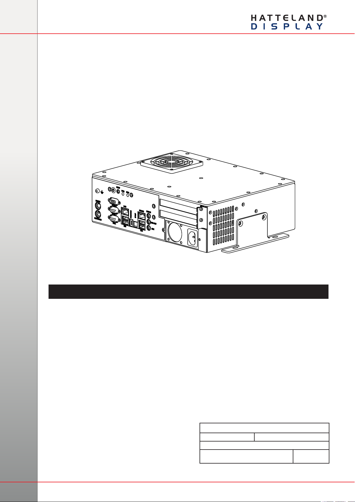
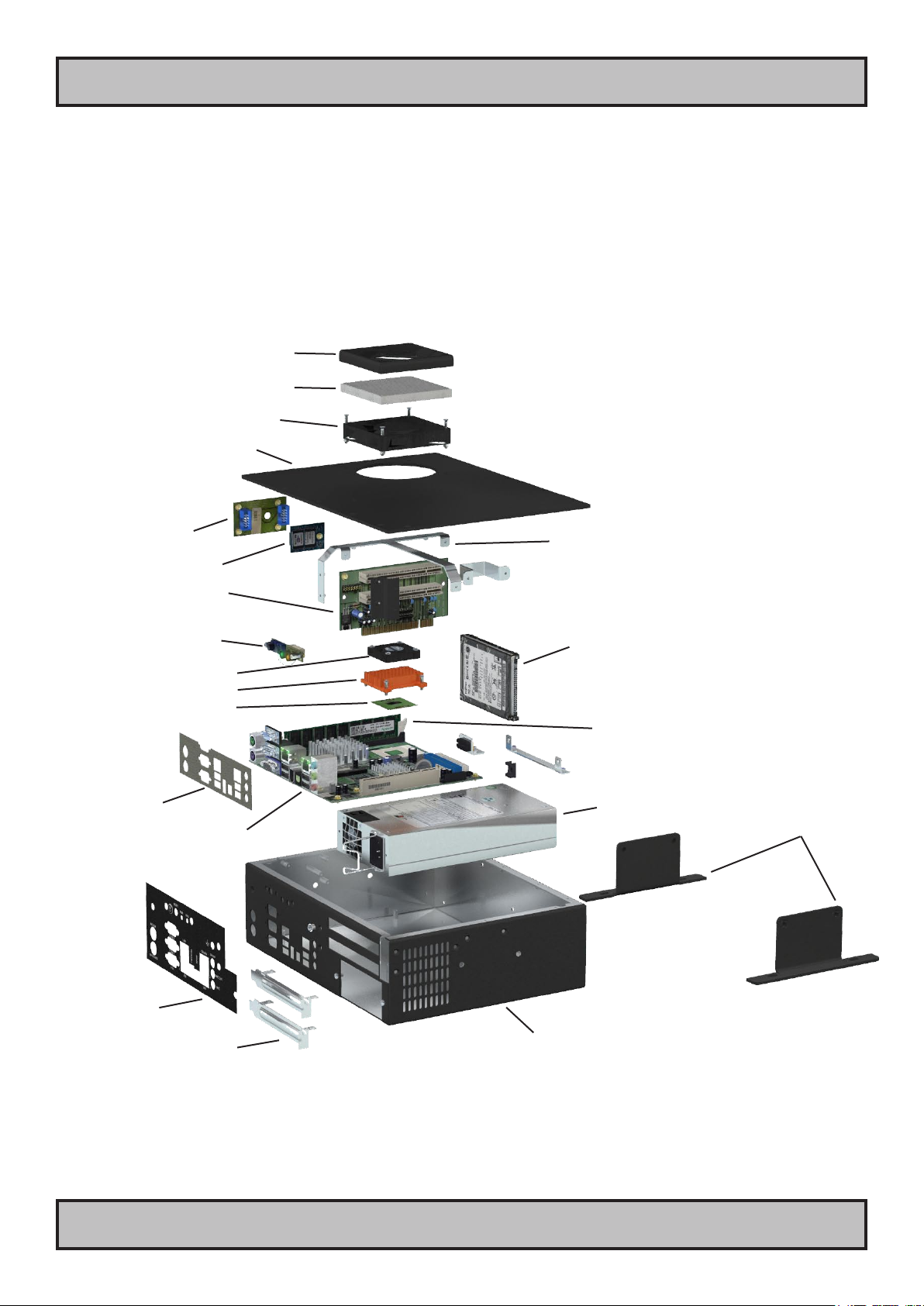
Basic Construction
Compact Computer
Basic Construction - Compact Computer
General illustration
Fan Cover
Fan Filter
Fan
Cabinet Top Cover
uDOC Adapter
uDOC Disc (option)
Support Brackets
PCI Raiser Card
User Controls 2,5” IDE Drive (option)
Processor Fan
Processor Cooling
Processor
Mainboard
Memory
Power Module
Connector Label
PCI Slot Brackets Computer Chassis
Mounting Brackets
(option)
Grounding Support
9
IND100240-8
INB100031-1 (Rev 9)
General
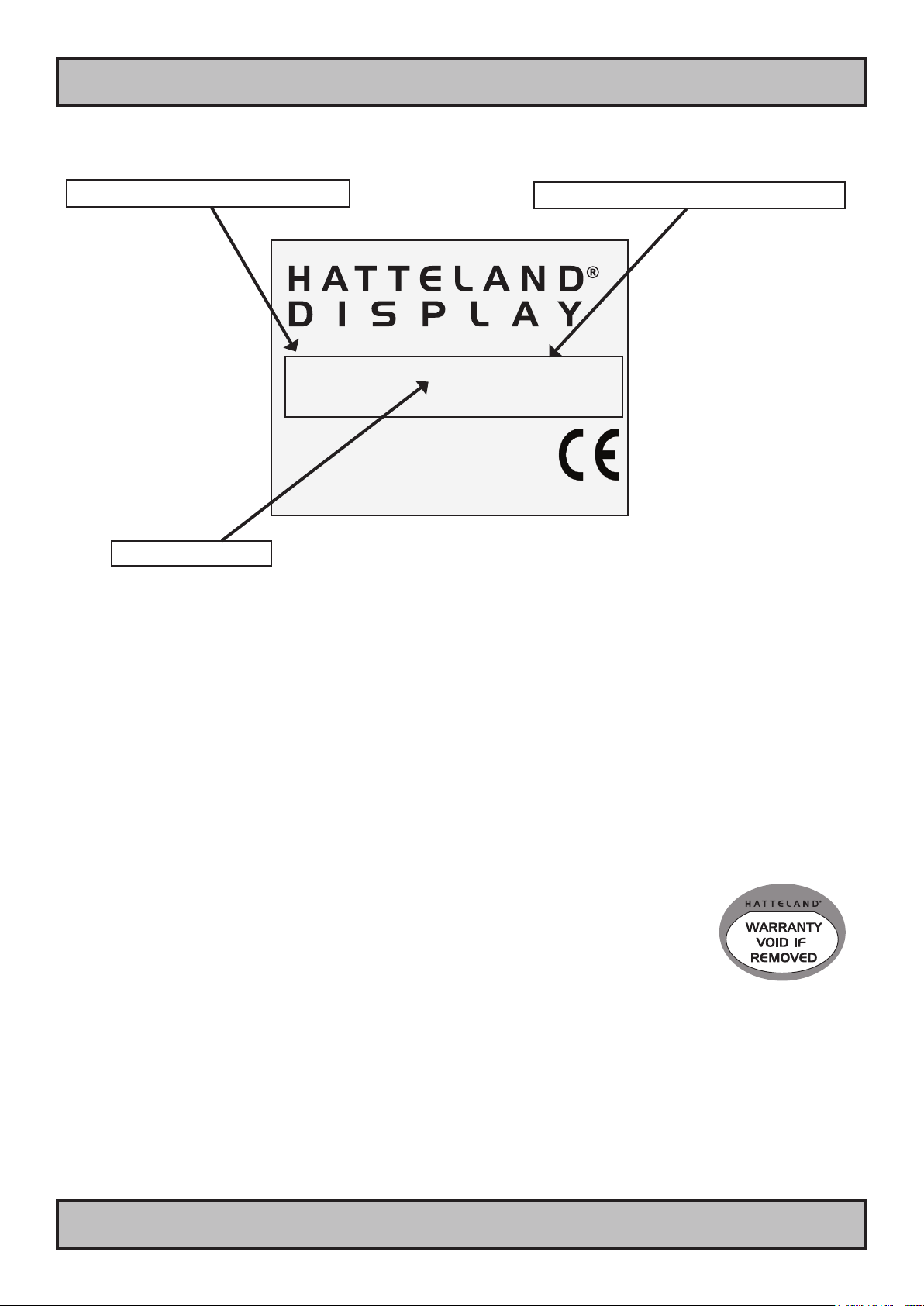
Product Information
Manufacturer: Product: Product type:
Hatteland Display Computer HT B04PM STD-A1
Serial Number
NORWAY HT B04PM STD-A1-121
Product Labels (Example)
Serial Number Label
Manufacturer & Country Product Type & Serial Number
Description
Warranty Label
This label may be present on the product (hardware dependent). If you are to perform service
on a unit still under warranty, the warranty will be void if this label is attempted removed, re-
glued or removed completely. This label is usually located on the back of the product and
covers an mechanical gap/edge or protects a key screw. This is to enable service departments
determine if there has been any unauthorized service on a product still under warranty.
Serial Number Label Nomenclature
AA AXXAA AAA-AXX-XXXXXX NOMENCLATURE - A=Letters, X=Numbers
HT B04PM STD-A11-000135 Example
|| ||||| ||| ||| ||||||
|| ||||| ||| ||| ¤¤¤¤¤¤- Serial Number. Due to revisions, numbers may be 1 to 7 digits
|| ||||| ||| ||¤-------- Reserved for customized models.
|| ||||| ||| ¤¤--------- Power Input ID (x1=AC, x2=DC. x may be A,B,C,D)
|| ||||| ¤¤¤------------ Standard Product Term ID / Military Term ID / Reserved Cus ID
|| |||¤¤---------------- Processor Type (PM=Pentium,CM=Celeron) / Reserved Customer ID
|| |¤¤------------------ Electronics / Mainboard / Technology Revision ID (4 or 6)
|| ¤-------------------- Chassis Size ID (B=Blackbox Computer)
¤¤---------------------- Manufacturer ID / Product Series ID

10 INB100031-1 (Rev 9)
This page left intentionally blank

11 INB100031-1 (Rev 9)
Installation
12
IND100210-1
INB100031-1 (Rev 9)
Installation
Installation and mounting of computers
1. Units may be intended for various methods of installation or mounting (rack mounting, panel mounting,
bracket mounting, ceiling/wall mounting); for details, please see the relevant mechanical drawings.
2. Adequate ventilation is a necessary prerequisite for the life of the unit. The air inlet and outlet openings must
denitely be kept clear; coverings which restrict ventilation are not permissible. The product might be without
any ventilation aperatures which means pt.2 does not apply.
3. Exposure to direct sunlight can cause a considerable increase in the temperature of the unit, and might under
certain circumstances lead to overtemperature. This point should already be taken into consideration when
the bridge equipment is being planned (sun shades, distance from the windows, ventilation, etc.)
4. Space necessary for ventilation, for cable inlets, for the operating procedures and for maintenance, must be
provided.
5. To further improve the cooling of the unit we recommend installing Cooling Fans underneath blowing upwards
into the unit air inlet. This may be required in high temperature applications and also when there is reason to
expect temperature problems due to non-optimal way of mounting.
6. For DC powered computer units proper grounding must be achieved by connecting a wire from the unit’s
ground (GND) screw (as indicated on the unit with a icon) to the grounding in your installation setup.
The wire should have a cross sectional area of at least 6mm2. The GND screw is located near the
other I/O connectors. Please review the “Physical Overview” chapter for further help.
General mounting instructions
1. The useful life of the components of all Electronics Units generally decreases with increasing ambient
temperature; it is therefore advisable to install such units in air-conditioned rooms. If there are no such
facilities, these rooms must at least be dry, adequately ventilated and kept at a suitable temperature in order
to prevent the formation of condensation inside the unit.
2. With most Electronic Units, cooling takes place via the surface of the casing. The cooling must not be
impaired by partial covering of the unit or by installation of the unit in a conned cabinet.
3. In the area of the wheel house, the distance of each electronics unit from the magnetic standard compass or
the magnetic steering compass must not be less than the permitted magnetic protection distance. This
distance is measured from the centre of the magnetic system of the compass to the nearest point on the
corresponding unit concerned. The exact distance is often mentioned in the specic product specications.
4. Transportation damage, even if apparently insignicant at rst glance, must immediately be examined and be
reported to the freight carrier. The moment of setting-to-work of the equipment is too late, not only for
reporting the damage but also for the supply of replacements.
Cables
Use only high quality shielded signal cables. For RGB/DVI cables use only cables with separate coax for Red, Green
and Blue.
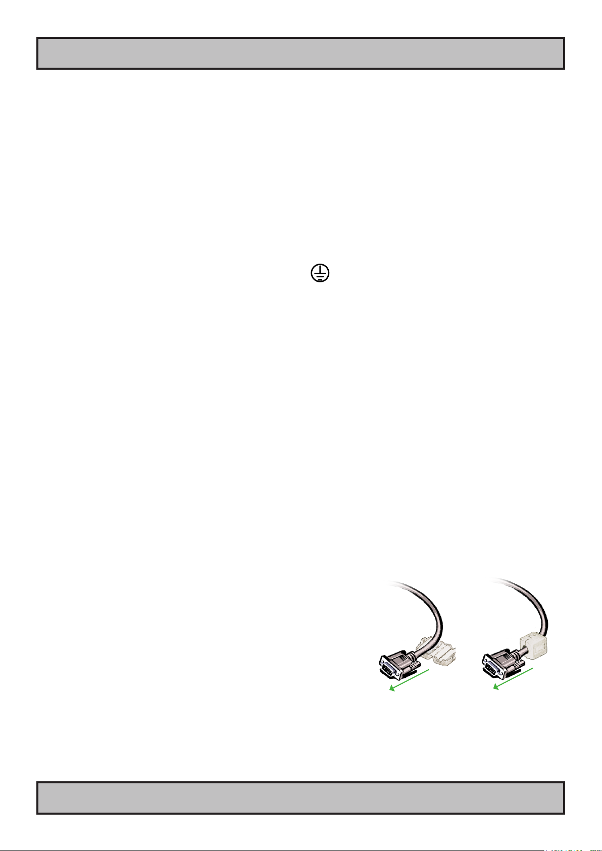
Ferrites
On selected products, the ferrites prevent high frequency
electrical noise (radio frequency interference) from exiting or entering
the equipment. To verify if your product require this, please see the
“Physical Overview” chapter in this manual. The ferrites are part of
the contents of the package also specied in the “Contents Of
Package” chapter early in this manual. The ferrites must be
mounted on specic cables to fully comply with the Type
Approvals!
The ferrites should be mounted (clipped in place on the cable as
shown in illustration) as close as possible to the cable connector
on the rear side of the computer product. Open up the ferrite,
place the cable inside as shown in FIG1, and then gently close it
until a click can be heard (FIG2).
General Installation Recommendations
FIG1
To computer
FIG2
To computer

13 INB100031-1 (Rev 9)
IND100133-20
Power Button & Power LED:
To turn ON the computer, press down button and release it immediately. The power indication (LED) will turn green
and any operating system will automatically boot. To turn OFF the computer, press down this button and hold it for 3
seconds. The operating system may require additionally tasks to be performed before computer shuts down and turns
off the unit.
Reset Button: (Hard Reset)
To reset the computer in case of software failure, press this button (it is mounted behind the edge of the casing, to
access it use a screwdriver or a pen), This reset button is a hard reset which means the operating system will NOT
be warned. Using this reset method may damage les and / or operating system in worst case scenarios. Precaution
should be taken when using this.To perform a safe software reset, press either the power button, or use the operating
system own reset functionality if possible.
Hard drive LED (HDD LED):
The hard drive indication (LED) will turn orange when there occur read / write activity to / from the hard drive.
PS/2 Mouse and PS/2 Keyboard INPUTS:
Connect the PS/2 mouse cable to the PS/2 5P Connector (female) marked with MOUSE.
Connect the PS/2 keyboard cable to the PS/2 5P Connector (female) marked with KEYBOARD.
Connector area of computer
NOTE: Available connectors / locations (may) vary depending on model !
Physical Overview - HT B06xM STD
PCI Slot 2
PCI Slot 1 Power Input
USB 1,2
Mouse Port
RGB Out
GND Screw
Power On/Off Button
Reset Button
Power LED
HDD LED
Keyboard Port
COM2
COM1
Network LAN
Network Gigabit LAN
FireWire
SPDIF
USB 3,4
Audio Line In, Line Out, Mic
Physical Overview - HT B06xM STD
14 INB100031-1 (Rev 9)
IND100133-20
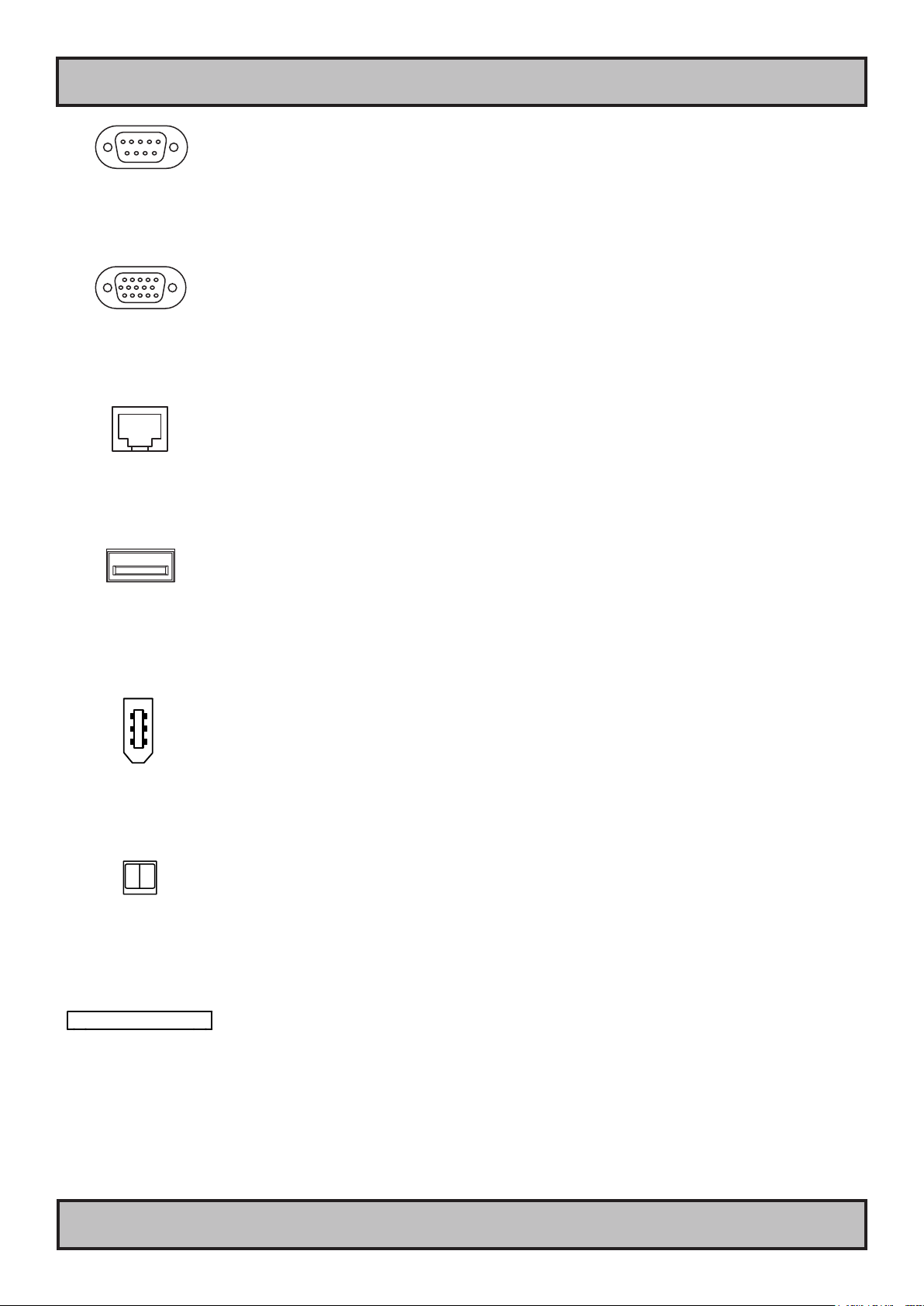
COM1,2 Serial Ports INPUT/OUTPUT:
Supports RS232 using D-SUB 9P Male connectors. Fasten the cable to the connector using the provided screws on
the cable housing itself.
RGB OUTPUT:
Will output a signal from the computer for use with external display or monitor. Connects via a High Density D-SUB
15P Female connector. Fasten the cable to the connector using the provided screws on the cable housing itself.
Network INPUT/OUTPUT:
Supports 10/100Mbps Ethernet (LAN) and 10/100/1000Mbps Ethernet (GBLAN). Suitable for twisted pair cables
CAT.5E. Make sure the network cable connector ”clicks” into the RJ-45 connector.
USB1,2,3,4 INPUT/OUTPUT:
Supports any USB1.1 (12Mbps) or USB2.0 (480Mbps) compliant peripherals. Drivers for most USB devices are
usually included in operating system or on separate installation CD’s delivered with Third Party products. USB 1.1
devices will operate in USB 1.1 mode (12 Mbps).
IEEE1394 Firewire INPUT/OUTPUT:
Supports any compliant Firewire peripherals. Drivers for most Firewire devices are usually included in operating
system or on separate installation CD’s delivered with Third Party products. Firewire operates with 400 Mbps.
SPDIF OPTICAL TOSLINK OUTPUT:
Enables optical transfer of the audio signal out to any optical SPDIF compliant equipment with the appropriate cable.
The optical interface is protected behind 2 mini hinged plastic doors which will slide away when a connector/cable is
inserted gently.
PCI Slots 1&2:
Supports PCI (Half Length Prole. 3V & 5V) card in two available slots. These PCI cards are normally factory installed.
In order to mount PCI cards yourselves, the top plate of the unit must be removed and the corresponding PCI bracket
removed. All cables or power etc. must be disconnected when installing PCI cards. Please see NOTES chapter for
general guidelines.

Physical Overview - HT B06xM STD
15 INB100031-1 (Rev 9)
IND100133-20
Power INPUT: (AC or DC Model)
AC MODEL ONLY:
The internal AC power module supports both 115VAC/60Hz and 230/50Hz power
input using a standard IEC European power plug.

16 INB100031-1 (Rev 9)
This page left intentionally blank

17 INB100031-1 (Rev 9)
Specications
18 INB100031-1 (Rev 9)
IND100129-72
Specications - HT B06xM STD
PRODUCT SPECIFICATIONS - HT B06xM STD
2/2
T E C H N I C A L D E S C R I P T I O N
A P P R O V A L S & C E R T I F I C A T E S
These products have been tested / type approved by the following classification societies:
HT B06PM STD-Ax:
EN60945 4th (IEC945 4th) IACS E10 DNV - Det Norske Veritas BV - Bureau Veritas
ABS - American Bureau of Shipping ClassNK - Nippon Kaiji Kyokai GL - Germanischer Lloyd LRS - Lloyd's Register of Shipping
HT B06CM STD-Ax:
EN60945 4th (IEC945 4th), IACS E10 ClassNK - Nippon Kaiji Kyokai GL - Germanischer Lloyd DNV - Det Norske Veritas
Standard Computer Specifications:
Power Specifications:
Physical Specifications:
• 290 (W) x 88.9 x (H) x 223 (D) mm - 11.42" (W) x 3.50" x (H) x 8.78" (D)
• Weight: 4 kg (approx)
• Aluminium Chassis
• Mounting Brackets
Available Global Component Options:
Connector Type:
Connector Type:
• Installed OS : None, please speciy when ordering
• Processor : See options below.
• Storage Solutions : See options below.
• System Chipset : Intel® 915GM, ICH6M
• Graphics Chipset : Intel® Graphics Media Accelerator (GMA) 900 - Up to 2048 x 1536, 32-Bit @ 85Hz 1 x HDDB15F
• BIOS : Award Flash BIOS
• Memory : From 256 to 1GB option (DDR2, 533Mhz, Non-ECC, 1 slot on-board)
• PCI Slots : 2 x PCI2.2 Slots 32-bit, 3V and 5V Interface, Half Length Profile
• Firewire : 1 x IEEE1394 Firewire 400Mbps - TI TSB43LV22** 1 x IEEE1394 FireWire
• Serial Ports : 2 x RS-232 2 x DB9M
• Primary Ethernet : 1 x 10/100 Mbps, Intel 82562ET ICH6M Integrated 1 x RJ-45
• Secondary Ethernet : 1 x 10/100/1000 Mbps Marvell 88E8053 PCI Express Gigabit Lan 1 x RJ-45
• USB Ports : 4 x USB2.0 - 480Mbps 4 x USB
• Keyboard Port : 1 x Standard PS/2 mini DIN connector 1 x PS/2
• Mouse Port : 1 x Standard PS/2 mini DIN connector 1 x PS/2
• Power Manager : APM V1.2 and ACPI
• Monitoring : On-board W83627HF, monitors system temperature and voltage status
• Audio : AC-97 ALC655, 6 channel with LINE IN, LINE OUT, MIC IN + SPDIF** 3 x 3.5mm jacks +
1 x TOSLINK
**Note: IEEE1394 Firewire and SPDIF connectors was not included in the EN60945 4th (IEC945 4th) testing.
Power Supply Options:
• 115VAC/60Hz or 230VAC/50Hz : Model HT B06xM STD-y1 (200W) STD IEC
• Power Consumption - Operating : TBD (MAX)
Note: All specifications are subject to change without prior notice!
HT B06CM STD-A1:
• 1 x Intel® Celeron®M 1.5GHz, 400MHz FSB, 1MB L2 Cache 90nm, Socket 479
(Upgradeable to 1.70GHz)
Processor Options:
Compass Safe Distance: HT B06PM STD Standard: 125cm Steering: 90cm
HT B06CM STD Standard: 125cm Steering: 90cm
Connector Type:
• 1 x uDOC Int. Module : uDOC (USB 2.0 Flash Disc) up to 4GB and future support for larger sizes possible.
• 1 x SATA HDD : 2.5" SATA HDD up to 120GB, 5400RPM, 8MB Cache
• Memory : From 256MB to 1GB
• Single or Dual DVI-D Outputs. (Not type approved) 2 x DVI-D24F
Note: These options are factory installed.
Environmental Considerations:
• Operating : Temperature -15 deg. C to +55 deg. C
Humidity up to 95%
• Storage : Temperature -20 deg. C to +60 deg. C
Humidity up to 95%
Safety Considerations:
Even although the test conditions for bridge units provide for a maximum
operating temperature of 55°C, continuous operation of all electronic
components should, if possible, take place at ambient temperatures of only
25°C. This is a necessary prerequisite for long life and low service costs.
M E C H A N I C A L D E S C R I P T I O N

19 INB100031-1 (Rev 9)
Technical Drawings

20 INB100031-1 (Rev 9)
IND100132-95
Technical Drawings - HT B06xM STD-A1
This document is the property of Hatteland Display AS. This document and any authorized reproduction thereof, must not be used in any way against the interest of Hatteland Display AS.
Any authorized reproduction, in whole or in part, must include this legend. Hatteland Display Proprietary information. Not to be distributed to any third party without written permission.
Dimensions might be shown with or without decimals and indicated as mm [inches]. Tolerance on drawings is +/- 1mm. For accurate measurements, check relevant DWG le.
This manual suits for next models
2
Table of contents
Other Hatteland Marine Equipment manuals


