VDH Heinen & Hopman FC500-PC User manual

Manual FC500-PC Airco Doc. nr.: 012257
Type: Manual Number of pages: 43 Date: 16-02-2011
File: Do012257 FC500-PC v19 EN.wpd By: RvdT Version: V1.9
VDH Products B.V. Signed: File: Doc'01
Manual FC500-PC
Heinen & Hopman
VDH Doc. 012257

Doc. nr. : 012257 Version: V1.9 Date: 16-02-2011
VDH Products B.V. Type: MANUAL FC500-PC Page: 2 of 43
Disclaimer
The information contained in this document is assumed to be accurate. However VDH Products BV
accepts no liability for any mistakes or errors and has the right to change this document without notice.
Copyright Notice
Copyright 2001 VDH Products BV, Roden The Netherlands.
No part of this document may be reproduced without the prior written permission of VDH Products BV.
Edition
v1.0 1st edition 19-12-2001 Pre-release edition
v1.1 1st production edition 29-01-2002
v1.2 2e production edition 22-02-2002 Costumer remarks aided
v1.3 3e production edition 08-07-2002 Added M/S configuration setting Pag. 21,22
v1.4 4e production edition 20-08-2003 Added 4-button-display shielded cable, PU3
v1.5 5e production edition 06-01-2004 Added Parameter 93 (0=Alfanet, 1=Modbus) SW:V1.06
v1.6 6e production edition 16-08-2004 Correction P35: 0..2 humidity control (no, readout,
readout+control) SW:V1.06
v1.7 7e production edition 28-07-2005 Added pullup/down jumpers for signal conditioning,
changed network connections
v1.8 8e production edition 14-11-2005 SW:V1.09 Added P75, P76 setpoint limits and
P80 ....P89 settings for auto fan-speed
v1.9 9e production edition 16-02-2011 SW:V1.11 Added at P24 option 2 fan is running.

Doc. nr. : 012257 Version: V1.9 Date: 16-02-2011
VDH Products B.V. Type: MANUAL FC500-PC Page: 3 of 43
INTRODUCTION
This document describes the working and control of the Heinen & Hopman Airco-control FC500-PC.
The FC500-PC Airco-control consist of:
1) FC500-PC: Main Panel
2) FC400-BP: Control Panel FC400 type (four button)
3) MDR-BP Control Panel MDR-BP (three button)
4) FC500-sens: Sensors (Water- Air- en Outside-sensor)
5) RH95-2: Humidity sensor
WARNINGS
It is highly recommended to study the operation
of the FC500-PC Airco-control-system
carefully before using it.
Before connection the FC 500-PC to the supply, check
the supply voltage indicated on the internal sticker !!

Doc. nr. : 012257 Version: V1.9 Date: 16-02-2011
VDH Products B.V. Type: MANUAL FC500-PC Page: 4 of 43
OVERVIEW FC500-SYSTEM

Doc. nr. : 012257 Version: V1.9 Date: 16-02-2011
VDH Products B.V. Type: MANUAL FC500-PC Page: 5 of 43

Doc. nr. : 012257 Version: V1.9 Date: 16-02-2011
VDH Products B.V. Type: MANUAL FC500-PC Page: 6 of 43
TABLE OF CONTENTS:
INTRODUCTION ..................................................................3
WARNINGS ............................................................3
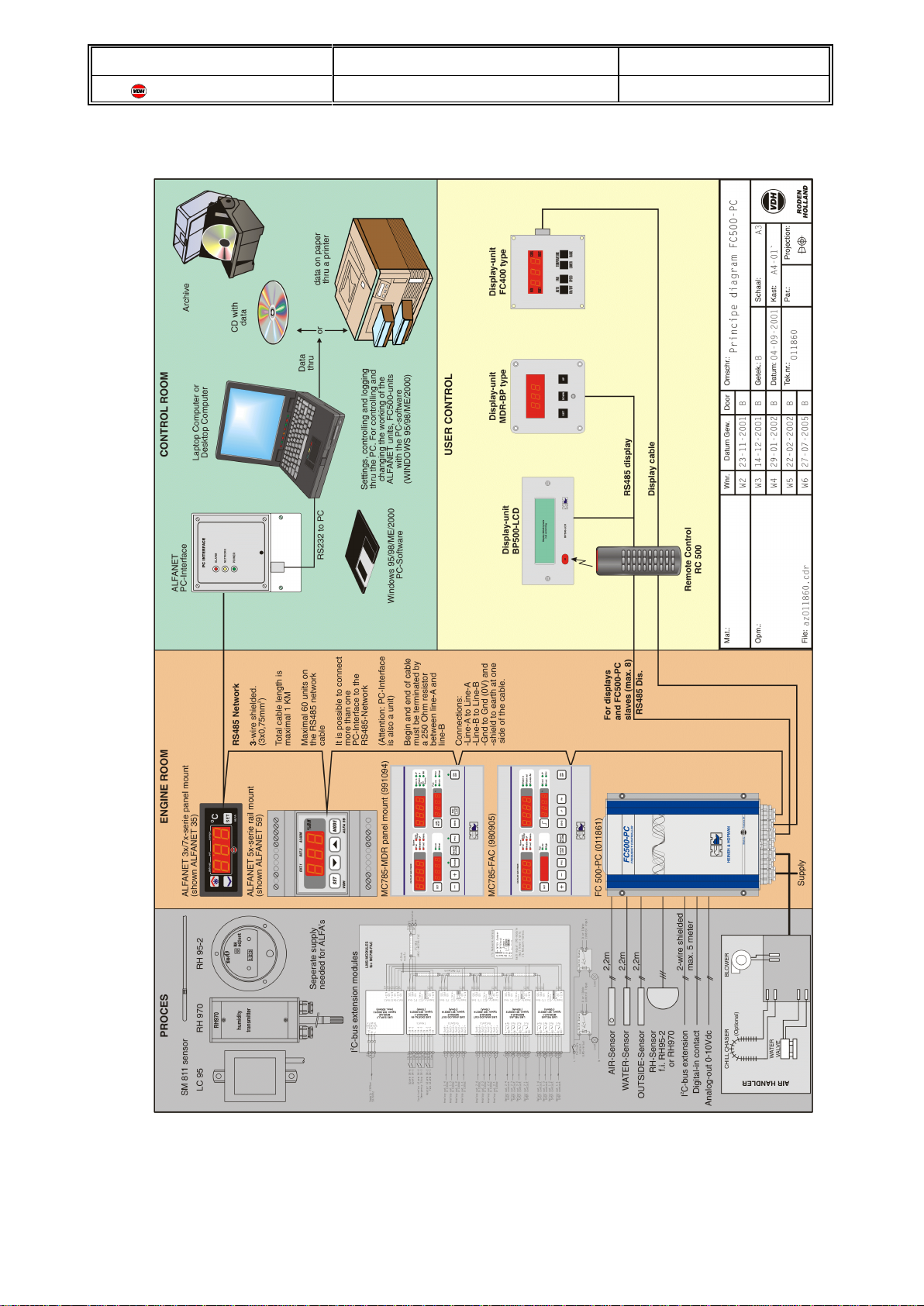
OVERVIEW FC500-SYSTEM ..............................................4
TABLE OF CONTENTS .............................................................6
TECHNICAL DATA ................................................................8
SAFETY INSTRUCTIONS ..........................................................10
ELECTRIC SHOCK PREVENTION .........................................10
FIRE PREVENTION ....................................................10
INJURY PREVENTION ..................................................10
ADDITIONAL INSTRUCTIONS ............................................11
Transportation and Installation ....................................11
Wiring .......................................................12
Trial Run .....................................................12
Emergency Stop ...............................................13
Operation .....................................................13
Maintenance, Inspection and Parts Replacement ......................13
Disposing of the Unit ............................................13
General Instructions ............................................13
INSTALLATION ..................................................................14
Unpacking the FC500-PC unit .............................................14
Installation of the FC500-PC ..............................................14
Opening front-cover of the FC500-PC .......................................15
Terminal connection diagram of the FC500-PC ...............................16
Power connection terminals of the FC500-PC .................................17
Power connections .............................................17
Supply connection ..............................................17
Air Handler connection ..........................................18
Control connection terminals of the FC500-PC ................................19
Control connections .............................................19
T1 = Air temperature sensor connection .............................19
T2 = Water temperature sensor connection ..........................19
T3 = Outside temperature sensor connection .........................19
Humidity sensor connection ......................................20
I2C-BUS connection .............................................20
Analog output connection ........................................20
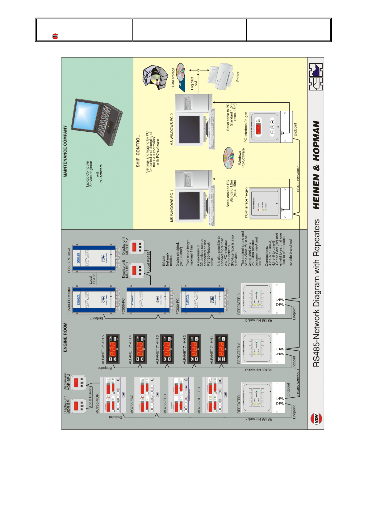
RS485-NET communication connection .............................21
RS485-DIS (Local) communication connection .......................22
Display data connection .........................................23
CONTROL ......................................................................24
Switching the controller on or off ...........................................24
Adjusting the temperature: ................................................24
Adjusting the fan speed: .................................................24
Adjusting the fan speed without temperature control: ...........................24
Switching off the display: .................................................25
Viewing other measurements: .............................................25
PROGRAMMING PARAMETERS ....................................................25
Parameters .................................................................26
Setting Master/Slave configuration (P91) .........................................27
Setting the RS485 as ALFANET or as MODBUS configuration (P93) ...................28
Night temperature offset (P70) ..................................................28
Setting 230Vac output (P51..P66) ...............................................28
Setting 120Vac output (P51...P66) ..............................................29

Doc. nr. : 012257 Version: V1.9 Date: 16-02-2011
VDH Products B.V. Type: MANUAL FC500-PC Page: 7 of 43
ERROR CODES ..................................................................31
Troubleshooting ........................................................31
INSTALLATION ..................................................................32
Frontview FC500-PC control-unit ..........................................32
Internal view FC500-PC ..................................................33
Connections FC500 .....................................................34
Standard Connections FC500-PC ..........................................35
Mounting instructions FC500-PC ...........................................36
Dimensions FC500-PC ..................................................37
Internal sideview FC500-PC ..............................................38
External bottom view ....................................................38
APPENDIX-A. MDR-BP remote panel .................................................39
Control ...............................................................39
Switching the controller on or off ...................................39
Adjusting the temperature ........................................39
Adjusting the fan speed ..........................................39
Adjusting the fan speed without temperature control ...................39
Switching off the display .........................................39
Viewing other measurements .....................................40
Programming local parameters ............................................40
Local parameter table ...........................................40
Error codes ...........................................................41
Troubleshooting ................................................41
Technical data .........................................................41
Connections ...........................................................42
Connections MDR-BP panel ......................................42
Connections RS485 network ......................................42
APPENDIX-B. FC400-BP control panel ................................................43
Frontview FC400-BP Panel ...............................................43
Dimensions FC400-BP panel .............................................43

Doc. nr. : 012257 Version: V1.9 Date: 16-02-2011
VDH Products B.V. Type: MANUAL FC500-PC Page: 8 of 43
TECHNICAL DATA:
FC 500-PC 230 Vac
Power supply voltage : 180Vac .. 245Vac
Power supply frequency : 50/60Hz
On/Off switch before FC500-PC : min. 10A
Power supply cable : 2,5mm² (14 AWG) flexible or solid wiring stripped 9mm.
Fan-control output : 80 Vac .. 230Vac (20..50 or 20..60 Hz)
Maximal load fan-control output : 500VA (Max. 2,2 Amp).
Water valve output : 230Vac
Chill chaser (heater) : 230Vac
Internal fuses : F2-1 Supply internal electronics-1 315 mA Slow
F3-2 Supply internal electronics-2 315 mA Slow
F4-2 Fan supply (N) 6,3 Amp. Slow
F5-2 Fan supply (L) 6,3 Amp. Slow
F1-2 Heating 10 Amp. Slow
F2-2 Water valve 1 Amp. Slow
EPROM Version : 230Vac Version V1.09
FC 500-PC 120 Vac
Power supply voltage : 100Vac .. 130Vac
Power supply frequency : 50/60Hz
On/Off switch before FC500-PC : min. 10A
Power supply cable : 2,5mm² (14 AWG) flexible or solid wiring stripped 9mm.
Fan-control output : 42 Vac .. 120Vac (20..50 or 20..60 Hz)
Maximal load fan-control output : 260VA (Max. 2,2 Amp).
Water valve output : 120Vac
Chill chaser (heater) : 120Vac
Internal fuses : F2-1 Supply internal electronics-1 315 mA Slow
F3-2 Supply internal electronics-2 315 mA Slow
F4-2 Fan supply (N) 6,3 Amp. Slow
F5-2 Fan supply (L) 6,3 Amp. Slow
F1-2 Heating 10 Amp. Slow
F2-2 Water valve 1 Amp. Slow
EPROM Version : 120Vac Version V1.09
General
Dimensions :FC500-PC (HxWxD) 250 x 170 x 142 mm
FC400 Display (HxWxD) 102 x 102 x 44 mm
Temperature ranges : Setpoint +9/+29C (+48/+85F)
Air sensor -20/+100C ( -4/+212F)
Water sensor -20/+100C ( -4/+212F)
Default settings : See parameter list
Inputs :Air-sensor 2,2m (10K NTC)
Water-sensor 2,2m (10K NTC)
Outside-sensor 2,2m (10K NTC)
Humidity-sensor e.g. RH95-2 (3-wire RH-sensor)
Contact-input (Digital input)
Outputs : Analog output 0-10Vdc (Rload min. 10Kohm)

Doc. nr. : 012257 Version: V1.9 Date: 16-02-2011
VDH Products B.V. Type: MANUAL FC500-PC Page: 9 of 43
Communications :Display-unit FC400-type 4-button control-panel
(6-wire shielded data-cable with data-connector)
I2C-bus for extension with LMS-modules (SDA, SCL, 0V)
(2-wire shielded, min. 0,75mm2max. length 5m)
RS485-DIS (Local) (Line-A, Line-B, 0V en +12V supply)
For MDR-BP 3-button control-panel and FC500-Slave units
(3(or 4)-wire shielded, min.0,75mm2, max. Length 1Km)
RS485-NET, For communicating to network (ALFANET)
(A, B, 0V) (3-wire, shielded, min.0,75mm2, max. Length 1Km)
Operation temperature : 0 /+40C (non-freezing)
Storage temperature : -20/+65C
Operation humidity : 90%RH or less (non-condensing)
Ambience : Indoors in a ventilated area (free from corrosive gas, flammable
gas, oil mist, dust, dirt en water (see operation humidity))

Doc. nr. : 012257 Version: V1.9 Date: 16-02-2011
VDH Products B.V. Type: MANUAL FC500-PC Page: 10 of 43
SAFETY INSTRUCTIONS:
ELECTRIC SHOCK PREVENTION
WARNING
• While power is on or when the FC500-PC is running, do not open the top cover of the
housing. You may get an electric shock.
•Do not run the FC500-PC with the top-cover removed. Otherwise, you may access the
exposed high-voltage terminals or the charging part of the circuitry and get an electric shock.
• If the power is off, do not remove the top-cover except for wiring or periodic inspection. You
may access the charged FC500-PC circuits and get an electric shock.
• Before starting wiring or inspection, switch power off, wait for more than 1 minutes.
• Ground the FC500-PC.
• Any person who is involved in the wiring or inspection of this equipment should be fully
competent to do the work.
• Always install the FC500-PC before wiring. Otherwise you may get an electric shock or be
injured.
• Operate only with dry hands to prevent an electric shock or be injured.
•Do not subject the cables to scratches, excessive stress, heavy loads or pinching. Otherwise,
you may get an electric shock.
•Do not change anything while power is on. It is dangerous to change while the power is on.
FIRE PREVENTION
CAUTION
•Mount the FC500-PC on an incombustible surface. Installing the equipment directly on or
near a combustible surface could lead to a fire.
• If the FC500-PC has become faulty, switch off the FC500-PC power. A continuous flow of
large current could cause a fire.
•Mount the FC500-PC in ventilated area’s only, overheating can lead to a fire.
INJURY PREVENTION
CAUTION
• Apply only the voltage specified in the instruction manual to each terminal to prevent damage
etc.
• Ensure that the cables are connected to the correct terminals. Otherwise, damage etc. may
occur.
• Always make sure that polarity is correct to prevent damage etc.
• While power is on and for some time after power-off, do not touch the FC500-PC as it is hot
and you may get burnt.

Doc. nr. : 012257 Version: V1.9 Date: 16-02-2011
VDH Products B.V. Type: MANUAL FC500-PC Page: 11 of 43
ADDITIONAL INSTRUCTIONS
Also note the following points to prevent an accidental failure, injury, electric shock, etc.
Transportation and Installation
CAUTION
• When carrying products, use correct lifting gear to prevent injury.
• Ensure that installation position and material can withstand the weight of the FC500-
PC. Install according to the information in the Instruction Manual.
•Do not operate if the FC500-PC is damaged or has parts missing.
•Do not hold the FC500-PC by the front cover; it may fall off.
•Do not stand or rest heavy objects on the FC500-PC.
•Check the FC500-PC mounting orientation is correct.(See also page 36)
• Prevent screws, wire fragments or other conductive bodies or oil or other flammable
substance from entering the FC500-PC.
• Place during installation a covering plate over the FC500-PC to prevent metal powder,
from drilling activity, being fallen into the unit. Remove covering plate always after
finishing installation otherwise, it will give a negative effect on the ventilation of the unit.
And the unit can even be overheated by it.
•Do not drop the FC500-PC or subject it to impact.
•Use the FC500-PC under the environmental conditions given in the technical data.

Doc. nr. : 012257 Version: V1.9 Date: 16-02-2011
VDH Products B.V. Type: MANUAL FC500-PC Page: 12 of 43
Wiring
CAUTION
•Do not fit capacitive equipment such as power factor correction capacitor, noise filter or
surge suppressor to the output of the FC500-PC. The unit is already provided with a
power factor correction circuit.
•Use only cables and wiring capable of withstanding temperatures of 70C.
• It is recommended to use insulation-sleeved solderless terminals for power supply,
heater, valve and fan wiring.
•Connect wires only when the unit is switched off, wait 1 minutes (internal capacitors
may be charged)
• Any person who is involved in the wiring or inspection of this equipment should be fully
competent to do the work.
• Always connect the earth to a earth with a resistance of 100 Ohm or less. If the earth
connection is not connected well you may get an electric shock.
•Check if the nominal supply voltage from the FC500-PC is equal to the AC-supply
voltage. A incorrect power supply voltage can lead to fire, injury or failure.
• Place interrupters, capable of switching off frequency controllers, like automatic-
MCCB-fuses, between the power supply and the FC500-PC and take other safety
actions to prevent short-circuit in the external wiring. If no safety action is installed, this
can lead to fire, injury or failure.
•Due to the static capacitance existing in the inverter I/O wiring and motor, leakage
current flow through them. These leakage currents may operate leakage circuit
breakers and earth leakage relays unnecessarily. Since their values depend on the
static capacitance etc. take the following measures. Place an earth leakage circuit
breaker suitable for frequency controllers. In general use a minimum 100mA selective
type (cable length is 1 meter or less, enlarge with 5mA for each extra meter). Use an
earth leakage circuit breaker which will detect leakage currents in the low frequency
range and that excludes high frequency leakage currents (selective type, durable
against harmonics and surges). For example Merlin Gerin: Selective series, Mitsubishi:
Progressive Super series.
•Take care for correct wiring which is firmly mounted otherwise measurement
mismatch, injury or damage to the unit can occur.
•Mount the screws on the connectors firmly. Tightening Torque 0,5-0,6 Nm.
•Do not connect a AC supply to the outputs terminals of fan, heater or water-valve. This
can lead to damage or failure of the unit.
WARNING
•Do not attach signal-data cables (display, RS485, sensors, I/O, etc.) to live cables,
antenna cables or cables with interference signals.
•Distance between signal-data cables and cables with interference should be more than
30cm but at least 10cm.
• Better is to have separate cable channels for signal-data cables and cables with
interference signals (Cable channels with separation must be in full metal).
Trial Run
CAUTION
•Check all parameters, and ensure that the machine will not be damaged by a sudden
start-up.

Doc. nr. : 012257 Version: V1.9 Date: 16-02-2011
VDH Products B.V. Type: MANUAL FC500-PC Page: 13 of 43
Emergency Stop
CAUTION
• Provide a safety backup such as an emergency brake which will prevent the machine
and equipment from hazardous conditions if the FC500-PC fails.
Operation
WARNING
•Do not modify the equipment
•Use a single-phase fan motor only. Connection of any other electrical equipment to the
FC500-PC may damage the equipment.
•The electronic over-current protection does not guarantee protection of the motor from
overheating.
•Do not use a magnetic contactor on the FC500-PC input for frequent starting/stopping
of the FC500-PC.
• Before changing the settings of the FC500-PC fully examine the performances of the
motor.
• Before running a FC500-PC which had been stored for a long period, always perform
inspection and test operation.
•For a good performance the FC500-PC must be installed in a room which is not
applied to extreme temperature changes.
• When the FC500-PC is mounted in a closed switchboard panel this panel should have
a cooling fan or airco to provide a ambient temperature of maximum 40C.
•The case temperature of the FC500-PC may be 30C higher than the ambient
temperature.
Maintenance, Inspection and Parts Replacement
CAUTION
•Check the environment of the FC500-PC regularly, to obtain good working conditions.
•Do not carry out a megger (insulation resistance) test on the control circuit of the
FC500-PC.
•Replace parts only when the FC500-PC is switched off, wait 10 minutes and then open
up the unit to replace the needed part.
Disposing of the Unit
CAUTION
•Treat as industrial waste.
General Instructions
CAUTION
•Many of the drawings and diagrams in this manual show the FC500-PC without a
cover, or partially open. Never operate the unit like this. Always replace the cover and
follow this manual when operating the FC500-PC.

Doc. nr. : 012257 Version: V1.9 Date: 16-02-2011
VDH Products B.V. Type: MANUAL FC500-PC Page: 14 of 43
Figure-1 Clearances
INSTALLATION:
This manual is written for the FC500-PC frequency controller.
Incorrect handling may cause the FC500-PC to operate incorrectly, causing its life to be reduced
considerably, or at the worst, the FC500-PC to be damaged. Handle the unit properly in accordance
with the information in each section as well as the precautions and instructions of this manual to use it
correctly.
Unpacking the FC500-PC unit
Unpack the FC500-PC and check the unit for discrepancy, damage etc. If found such please
contact your sales representative.
Installation of the FC500-PC
1) Place the unit with the restrictions for the clearances around the unit as shown in figure.1
2) Note on ambient temperature. The units live is under great influence of ambient
temperature. In the place of installation, ambient temperature must be within the
permissible range of 0C to +40C. Check that the ambient temperature is within that
range in the positions shown in figure.2

Doc. nr. : 012257 Version: V1.9 Date: 16-02-2011
VDH Products B.V. Type: MANUAL FC500-PC Page: 15 of 43
Figure.2 Ambient temperature
3) The unit must be mounted vertically (mounting bolts on the wall) to get a good airflow
through the unit, as shown in fig.1 (above), on an installation surface securely and
vertically with screws or bolts.
4) Install the unit in a place where it is not affected by vibration easily (5,9m/s2{0,6G}
maximum). Note the vibration of a cart, press, etc.
5) Install the unit on a non-combustible surface (e.g. metal). The unit will be hot. Also leave
sufficient clearances around the unit (fig.1).
6) The unit must be cooled by fan or airco when installed in an enclosure. When two or
more units are installed, these units may not be installed above each other. Make sure
the airflow comes under and through the unit.
7) Avoid places where the unit is exposed to oil mist, flammable gases, fluff, dust, dirt etc.
Install the unit in a clean place or inside a “totally enclosed” panel which does not accept
any suspended matter.
Opening front-cover of the FC500-PC
At the bottom-side of the unit there is a screw for opening the
front-cover. Behind it is an eccentric to lift the front-cover from
its click holding position.
To install the front-cover again place the front-cover in its place
and gently click it in his holding position.

Doc. nr. : 012257 Version: V1.9 Date: 16-02-2011
VDH Products B.V. Type: MANUAL FC500-PC Page: 16 of 43
Terminal connection diagram of the FC500-PC
Standard terminal connection diagram drawing 012504w3:

Doc. nr. : 012257 Version: V1.9 Date: 16-02-2011
VDH Products B.V. Type: MANUAL FC500-PC Page: 17 of 43
Remove top-cover first before wiring the FC500-PC by turning the opening screw at the
bottom-side of the unit.
Power connection terminals of the FC500-PC
On the top Printed-Circuit-Board all power connections are made. For grounding the unit use
the grounding-strip inside the unit, this strip must be connected firmly to the ground connection
on the PCB. The unit must be grounded!!
Power connections:
Supply connection:
Symbol
PCB Cable
(colour) Cable
mm2Terminal
Name Description
PE (gr/ye) 2,5 SUPPLY
PE Ground connection for PCB, this terminal must
also be connected to the Ground-rail (housing)
LL (brown) 2,5 SUPPLY L Line supply connection
230Vac type: 180...245Vac
120Vac type: 100...130Vac
N N (blue) 2,5 SUPPLY N Neutral supply connection (0Vac)
Use a 3-wire 2,5mm2power cable (gr/ye, br, bl).

Doc. nr. : 012257 Version: V1.9 Date: 16-02-2011
VDH Products B.V. Type: MANUAL FC500-PC Page: 18 of 43
Air Handler connection:
Symbol
PCB Cable
(colour) Cable
mm2Terminal
Name Description
LL (black) 2,5 HEATER L Line heater output connection
230Vac type: 230Vac
120Vac type: 120Vac
N N (blue) 2,5 HEATER N Neutral heater output connection (0Vac)
LL (black) 2,5 VALVE L Line water valve output connection
230Vac type: 230Vac
120Vac type: 120Vac
N N (blue) 2,5 VALVE N Neutral water valve output connection
(0Vac)
L * L (black) 2,5
shielded FAN L Line fan output connection
230Vac type: 80...230Vac *
120Vac type: 42...120Vac *
L * L(black) 2,5
shielded FAN L Line fan output connection
230Vac type: 80...230Vac *
120Vac type: 42...120Vac *
*) Note since the fan output is controlled by a bridge circuit there is no neutral
connection to the fan only line-connections.
Use also a 2-wire 2,5mm2shielded cable for high frequency suppression to the fan.

Doc. nr. : 012257 Version: V1.9 Date: 16-02-2011
VDH Products B.V. Type: MANUAL FC500-PC Page: 19 of 43
Control connection terminals of the FC500-PC
On the top Printed-Circuit-Board all control connections are made. Connections see page 31.
Attention: All connections are made on the plugable connectors on the non text-side!
Control connections:
T1 = Air temperature sensor connection:
Symbol
PCB Cable
(colour) Cable
mm2Terminal
Name Description
Abr (brown) 0,34 T1 A Air-sensor connection (hot)
wh (white) 0,34 T1 Air-sensor connection (0Vm)
Cable is already connected to the sensor (br, wh)
T2 = Water temperature sensor connection:
Symbol
PCB Cable
(colour) Cable
mm2Terminal
Name Description
Abr (brown) 0,34 T2 A Water-sensor connection (hot)
wh (white) 0,34 T2 Water-sensor connection (0Vm)
Cable is already connected to the sensor (br, wh)
T3 = Outside temperature sensor connection:
Symbol
PCB Cable
(colour) Cable
mm2Terminal
Name Description
Abr (brown) 0,34 T3 A Outside-sensor connection (hot)
wh (white) 0,34 T3 Outside-sensor connection (0Vm)
Cable is already connected to the sensor (br, wh)

Doc. nr. : 012257 Version: V1.9 Date: 16-02-2011
VDH Products B.V. Type: MANUAL FC500-PC Page: 20 of 43
Humidity sensor connection:
Symbol
PCB Cable
(colour) Cable
mm2Terminal
Name Description
++12V (br) 0,75 RH + Humidity-sensor supply connection (V+)
SIG Signal (wh) 0,75 RH SIG Humidity-sensor signal connection
(0-1Vdc = 0-100%RH)
0V ( )0V com. (gr) 0,75 RH 0V Humidity-sensor common connection (0V)
Use a 3-wire 0,5mm2Cable (brown, white, green)
I2C-BUS connection:
Symbol
PCB Cable
(colour) Cable
mm2Terminal
Name Description
SDA SDA (br) 0,75 I2C-BUS
SDA I2C-Extensionbus connection (Data)
SCL SCL (wh) 0,75 I2C-BUS
SCL I2C-Extensionbus connection (Clock)
0V(shield) shield I2C-BUS I2C-Extensionbus connection (Shield)
Use a 2-wire shielded 0,75mm2Cable and connect SDA to SDA, SCL to SCL and Shield to
Shield at the next unit such as the LMS Digital-in Module.
Note: Maximum cable length of the complete I2C-bus is 5 meter!
Analog output connection:
Symbol
PCB Cable
(colour) Cable
mm2Terminal
Name Description
+ Ana.Out (br) 0,5 0..10V + Analog-output connection (0..10Vdc)
0V Com. (gr) 0,5 0..10V Analog-output connection (0V common)
Use a 2-wire 0,5mm2Cable (brown, white)
Table of contents
Popular Marine Equipment manuals by other brands

GST
GST C-9404(Ex) quick start guide

CDI
CDI 174-5456 Installation and troubleshooting guide

Aztech
Aztech AZ-120 installation guide

olympia electronics
olympia electronics ΒS-521/1 quick start guide

COBHAM
COBHAM Sea Tel Dual Antenna Arbitrator installation manual

Skipper
Skipper GDS101 Operation and installation manual