Ultraflex T67 Manual

T67
STEERINGSYSTEM
Installationandmaintenancemanual
PARTNER
R
ITALIANO
(Dr./Dis./Des. n°12884/b19/02/2015)
FRANÇAIS ENGLISH

DearCustomer,
We wouldliketo thankyoufor choosingan ULTRAFLEX product.
ULTRAFLEX hasbeenaleader insteeringsystemsforpleasureandprofessionalboatsfor manyyears.
ULTRAFLEX productionissinceeversynonimousof reliabilityandsafety.
All ULTRAFLEX productsare designedandmanufacturedtoensurethebestperformance.
To ensure yoursafety andto maintainahighquality level, ULTRAFLEX productsare guaranteedonlyif
theyareusedwithoriginalspareparts.
ULTRAFLEX and UFLEX QualityManagementSystemsare certifiedCISQ-IQNet bytheItalianShipping
Registry(RINA),inconformitywiththeUNIENISO9001:2008 rule. ULTRAFLEX certificationNo.6669/02/S
(former420/96). UFLEX certificationNo.8875/03/S.
Thequality managementsysteminvolvesall thecompanyresourcesandprocessesstartingfromthe
design,inorderto:
- ensure productqualitytothecustomer;
-maintainandimprove thequality standardsconstantly;
-pursueacontinuous process improvementto meet themarket needsandto increasethecustomer
satisfaction
ULTRAFLEX EnvironmentalManagementSystemiscertifiedCISQ-IQNet bytheItalianShippingRegistry
(RINA),inconformitywiththeUNIENISO14001rule. ULTRAFLEX certificationNo.EMS-1282/S.
Productsforpleasure boatsare constantlytestedtochecktheirconformitywiththe2013/53/EU.
ULTRAFLEX S.p.A.
ULTRAFLEX
16015Casella(Genova)Italia -ViaCrose,2
"ULTRAFLEX hasover 80 yearsof experience inthemarineindustry andisaworldleader intheproduction
ofmechanical,hydraulicandelectronicsteeringsystems,controlboxesandsteeringwheelsforany
kindof pleasure,fishingor commercialboats.
Thekey factorswhichexplaintheincreasingsuccess of ourproductsall over theworldare thereliability
of ourproductsandthebefore andafter saleservice,thequality of thecompanyorganizationandof the
humanresourcesandthecontinuousspendinginresearchanddevelopment".
ENGLISH

T67 STEERINGSYSTEM -page 3 of 43
Installationandmaintenancemanual
ULTRAFLEX
ENGLISH
SECTION1-PRODUCTDESCRIPTION
1.1 DESCRIPTION OFTHEPRODUCT AND WARNINGSFOR THECORRECT USE................................................6
1.2 DIMENSIONS..................................................................................................................................6
TABLEOFCONTENTS
SECTION2-TRANSPORT
2.1 GENERALWARNINGS.............................................................................................................................8
2.2 PACKAGINGCONTENTS...........................................................................................................................8
SECTION5-MAINTENANCE
5.1 ROUTINEMAINTENANCE.................................................................................................................14
5.2 EXTRAORDINARYMAINTENANCE.....................................................................................................14
SECTION3-INSTALLATION
3.1 NECESSARYTOOLS.................................................................................................................................9
3.2 HELMPOSITIONING..................................................................................................................9
3,3 CONNECTIONOFTHESINGLE CABLE TO THEHELM...............................................................................11
SECTION4-SAFETYWARNINGS
4.1 SAFETYRULESDURINGINSTALLATIONANDUSE............................................................13
4.2 CLOTHING.....................................................................................................................................13
SECTION6-DISMANTLING
6.1 DISMANTLING..........................................................................................................................14
!
MANUALUSEANDSYMBOLSUSED................................................................................................................4
INTRODUCTION......................................................................................................................................5
WARRANTY................................................................................................................................5

Installationandmaintenancemanual
ULTRAFLEX
page 4 of 43 - T67 STEERINGSYSTEM
ENGLISH
Inthismanualthefollowingsymbolsareusedtoensuretheusersafetyandtoguarantee thecorrect
operationoftheproduct:
MANUALUSE AND SYMBOLSUSED
THEINSTALLATION AND MAINTENANCE MANUAL is thedocumentgivenwiththeproductfromitssaletoits
replacementanddischarge.Themanualisanimportantpartoftheproductitself.
It is necessarytoreadcarefully themanual,beforeANY ACTIVITYinvolvingtheproduct,handlingand
unloadingincluded.
STERN
BOW
STARBOARD PORT
Thesymbolsasideindicateall theoperations
whichmustbecarriedoutby qualifiedorskilled
staff,inordertoavoidhazards.
DANGER ImmediatehazardswhichCAUSEseverepersonalinjuryordeath.
WARNING
CAUTION
Thesymbolasideindicates all theoperationswhichmustbecarriedout
byqualifiedorskilledstaff,inordertoavoidhazards.
Werecommendtrainingthestaffinchargeoftheproductinstallation
andcheckingtheirknowledge.
NOTICE Importantinformationforthecorrectinstallationandformaintenance,that
doesnotcauseanydamage.
Denotes thatahazard existswhichcanresult ininjuryordeathifproper
precautionsarenottaken.
Denotesareminderofsafetypracticesordirectsattentiontounsafe
practices whichcould result inpersonalinjuryordamagetothecraft or
componentsortotheenvironment.

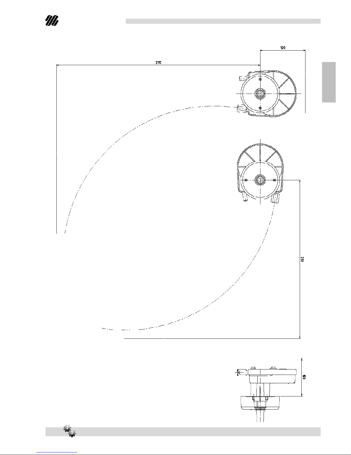
T67 STEERINGSYSTEM -page5 of43
Installationandmaintenancemanual
ULTRAFLEX
ENGLISH
WARRANTY
TECHNICALASSISTANCE SERVICE
INTRODUCTION
UFLEXS.r.l.
Via MiliteIgnoto,8A
16012 Busalla(GE)-Italy
Ph:+39.010.962.0239 (Italy)
Ph:+39.010.962.0244 (Abroad)
Fax: +39.010.962.0333
Email:ut@ultraflexgroup.it
www.ultraflexgroup.it
North-South-CentralAmerica:
UFLEX USA
6442 ParklandDrive
Sarasota, FL34243
Ph:+1.941.351.2628
Fax: +1.941.360.9171
Email:uflex@uflexusa.com
www.uflexusa.com
This installationandmaintenancemanualrepresentsanimportantpartoftheproductandmustbeavailable
tothepeopleinchargeofitsuse andmaintenance.
Theusermustknowthecontentofthis manual.
ULTRAFLEX declines allresponsibilityforpossiblemistakes inthismanualduetoprintingerrors.
Apartfromtheessentialfeaturesofthedescribedproduct, ULTRAFLEX reserves therighttomakethose
modifications, suchas descriptions, detailsandillustrations, thatareconsideredtobesuitableforits
improvement,orfordesignorsales requirements, atanymomentandwithoutbeingobligedtoupdatethis
publication.
ALL RIGHTSARERESERVED. Publishingrights, trademarks, partnumbersandpictures of ULTRAFLEX products
includedinthis manualare ULTRAFLEX property.
Greatcarehas beentakenincollectingandcheckingthedocumentationcontainedinthismanualto
makeitas completeandcomprehensibleas possible. Nothingcontainedinthis manualcanbeinterpreted
as warrantyeitherexpressedorimplied-including,notinarestrictedway,thesuitabilitywarrantyforany
specialpurpose. Nothingcontainedinthis manualcanbeinterpretedas amodificationorconfirmationof
thetermsofanypurchase contract.
Toensurethecorrectproductandcomponentoperation,theproductmustbeinstalledbyqualifiedstaff.
Incaseofpartdamageormalfunction,please contactthequalifiedstafforourTechnicalAssistance
Service.
WARNING
ULTRAFLEX guarantees thatitsproductsarewell designedandfree frommanufacturingandmaterialdefects,
foraperiodoftwoyearsfromthedateofmanufacturing.
Fortheproductswhichareinstalledandusedonworkingorcommercialboatsthewarrantyislimitedto
oneyearfromthedateofmanufacturing.
Ifduringthis periodtheproductproves tobedefectiveduetoimpropermaterialsand/ormanufacture, the
manufacturerwill repairorreplacethedefectivepartsfree ofcharge.
Directorindirectdamageis notcoveredbythis warranty.Inparticularthecompanyisnotresponsibleandthis
warrantywillnotcoverthedamageresultingfromincorrectinstallationoruseoftheproduct(exceptfor
replacementorrepairofdefectivepartsaccordingtotheconditionsandtermsabove).
This warrantydoes notcovertheproductsinstalledonraceboatsorboatsusedincompetitions.
Thedescriptionsandillustrationscontainedinthis manualshouldbeusedas generalreferenceonly.
ForanyfurtherinformationpleasecontactourTechnicalAssistanceService.
ULTRAFLEX steeringsystemcomponentsaremarkedaccordingtotheDirective2013/53/EU.
Weremindyouthatonly markedsteeringsystemsmustbeusedontheboatsmarked .

Installationandmaintenancemanual
ULTRAFLEX
page 6 of 43 - T67 STEERINGSYSTEM
ENGLISH
1.2 Dimensions
1PRODUCTDESCRIPTION
1.1 Descriptionoftheproductandwarningsforthecorrectuse
T67 mechanicalsteeringsystemis designedtocontrolboatsequippedwithoutboard engines.T67 steeringsystem
mustbeusedwith ULTRAFLEX M58 singlecable.
T67 steeringsystemis nottobeusedonboatsequippedwithengines thatexceedthemaximum horsepower
ratingoftheboatand/orthespeedof50knots(57.5 mph).This steeringsystemcomplies withEN29775 standard:
itcanbeusedwithoutboardengineswithpowerupto40kW(55 hp).Incase ofEvinrudeE-TECTM50 engines. itis
advisabletouseT85 orT71FCsteeringsystems.
DO NOT DISASSEMBLE ANY PARTOFTHEHELMDURINGTHEINSTALLATIONOFTHECABLE. THE
DISASSEMBLY OFTHECOMPONENTSCAN GENERALLY CAUSESERIOUSDAMAGE TO OBJECTSOR PEOPLE.
THISPROCEDURE CAUSESTHEWARRANTY LOSS OFTHEPRODUCT.
ThefollowingpicturesshowthedimensionsofT67helm.
WARNING
DANGER
145,6 (5.73")
76,6 (3.01") 69 (2.72")
123 (4.85")
96,5 (3.8") 59,7 (2.35")
T67

T67 STEERINGSYSTEM -page 7 of 43
Installationandmaintenancemanual
ULTRAFLEX
ENGLISH
ThefollowingpicturesshowtherequiredminimumdimensionsfortheassemblyofT67helmwithM58
singlecable.

Installationandmaintenancemanual
ULTRAFLEX
page 8 of 43 - T67 STEERINGSYSTEM
ENGLISH
Thepackagingmustbedisposedofaccordingtotheexistinglaws.
2.1 Generalwarnings
2TRANSPORT
Theproductweightwithitspackagingis2.5kg(5.5 pounds);therefore,itcanbemanuallyhandled.
2.2 Packagingcontents
Beforeusingtheequipmentcheckthattheproducthasnotbeendamagedduringtransportorstorage.
Also makesurethatall thestandard componentsareinthepackaging(see list).Incaseofdamage, notify
theclaimtotheforwarderandinformthesupplier.
WARNING
Thestaff inchargeofhandlingmustwearprotectiveglovesandsafetyshoes.
CAUTION
Contentsofthehelmpackagings:
C
T67
A
B
H
E
D
F
G
I
L
REF
T67
A
1helm
B
1bracket
C
1mountingbezel
D
4washers6.5x12
E
8nutsM6
F
4screwsM6x35
G
1screwM10x50
H
2self-threadingscrews
I
1washer
L
1ring

T67 STEERINGSYSTEM -page 9 of 43
Installationandmaintenancemanual
ULTRAFLEX
ENGLISH
3INSTALLATION
3.1Necessary tools
Phillips
screwdriver
2Openend
wrenches
10mm [0,395”]
Drill
3.2Steeringsystempositioning
1Thesinglecablemustbeinstalledonthesideoftheboatclosertothesteeringwheelshaft.
2Selectadirectpathwithaminimumnumberofbends.
Theminimum bendradiusforasinglecableis 8"(200mm).Amoreseverebendwill cause steeringfriction
andreduce thesinglecablelife.
WARNING
Openend
wrench
17mm [0,66”]
Slotted
screwdriver
4Byusingthesupplieddrillingtemplateposition
thehelminthechosenplace andcreate4holesof
diameter7mm (0, 28") andoneofdiameter67 mm
(2,64").
3Makesurethe
distancesbetween
theaxis oftheshaft
ofthehelmandthe
bulkheadsare
equalorlongerthan
thoseindicatedon
page7.
Thesteeringsystem
unitcanbeinstalled
in5different
positionswhich
allowthecableto
exitinthemost
suitabledirection.
NOTE
123
45

Installationandmaintenancemanual
ULTRAFLEX
page 10 of 43 - T67 STEERINGSYSTEM
ENGLISH
5Tightenthe bracket(1)tothe dashboard using
fourscrewsM6x35 (hexagonalhead)(2),four
washers(3)andfourself stoppingnutsM6(4)with
torqueof6Nm(53 lbsin).
6Insertthehelmshaftfromthebacksideof
thedashboard throughtheholeofthemounting
bracket.Thehelmcanbefixedin5different
positions(every 45°).Therightpositionwill be
determinedbythemountingsideofthesingle
cable.Place thehelmintheselectedposition
andaligntheholes formounting.Tightenthehelm
tothebracketwithfourM6self-lockingnuts(5)
withtorqueof6Nm(53 lbsin).
1
2
3
4
5
7Insertthering(6)onthehelmbezel
consideringthattheadjustingscrew(7)mustbe
alignedwiththemountingbezelhole(8).
8 Insertthemountingbezel(8)andbringingin
contactwiththedashboard(9).
Fix themountingbezel(8)tothedashboard (9)
bymeansoftwoself-threadingscrews(10).
FRICTIONADJUSTMENT
HOLE POSITION
6
7
8
10
9

T67 STEERINGSYSTEM -page 11 of 43
Installationandmaintenancemanual
ULTRAFLEX
ENGLISH
3.3Singlecableconnectiontothesteeringsystem
1Determinethecorrectentrypositionofthesinglecableintothehelmaccordingtotheproper
steeringsystem.
2Removeprotectivetube(16)fromcable
ULTRAFLEX M58 butpreserve it(see picture4)and
keepitclean.Insertthehelicalcableintothe
helm.
3Turnthesteeringwheelso as topull the
cableintothehelm,makingthecablesheathend
(17)touchthenut(18).
PUSHOR PULL TURNING DIRECTIONS
17
9Insertthesteeringwheel(11)onthehelm
shaft (12)aligningtherecess ofthehubwiththe
key (13)oftheshaft.
Insertthewasher(14)andscrewtheM10 screw
(15)onthehubofthesteeringwheel,withtorque
of35-40Nm(310-354 lbsin).
13
11
14
15
12
Do notuse asteeringwheelwithdiameterwiderthan380 mm (15").
WARNING
18
16

Installationandmaintenancemanual
ULTRAFLEX
page 12 of 43 - T67 STEERINGSYSTEM
ENGLISH
4Turnthehelmnut(18)toscrewthecable
sheathend(17)untilittouches it.Theninsertthe
protective tube(16)removedbefore(see pic.2)
andplaceitonthecablecomingfromthehelm
untilthethehelmtubeis covered.
6 Makesurethedirectionofthesteeringwheelrotationcorrespondstotheboatdirection.
This controlmustbecarriedoutbeforetheboatis operatedinthewater.
WARNING
18
17
5Fix thecable sheathevery2m(6').Thesheath
mustnotbefixedtotheelectric wires.
Bulkheadopeningsrequireaminimum 38mm
(11/2)holediameter.
Makesurethesinglecablesheathdoes notenterincontactwithcuttingedges thatcould damageit.
DANGER
DANGER
Duringthesinglecableassemblyonthehelm,preventanydustor
foreignmaterialfromcomingincontactwithcableendandthehelm
itself.
7To modifythesensitivityofthesteeringwheel
itispossibletoadjustthefrictionpositionedon
thehub.Bymeansofaslottedscrewdriver(X),
actonthescrew(7)throughthemountingbezel
hole.
X
7
16
2m 2m

T67 STEERINGSYSTEM -page 13 of 43
Installationandmaintenancemanual
ULTRAFLEX
ENGLISH
4SAFETYWARNINGS
Thissectionshowsthesafetyruleswhichmustbefollowedforthecorrectequipmentoperation.
Werecommendreadingcarefullythis sectionandalso theothermanualssuppliedwiththesteeringsystem
components.
4.1 Safety rulesduringinstallationanduse
OBSERVESTRICTLYthefollowingsafetyrules:
ULTRAFLEX declines all responsibilityincase theuserdoes notfollowthese rules anditis notresponsiblefor
negligencewhileusingthesystem.
-DONOTPUTYOURHANDSBETWEENMOVINGPARTS.
-Donotdisablethesafetydevices.
-Do notmodifyoradd devices tothesystem,without ULTRAFLEX writtenauthorisationortechnical
interventionwhichwill prove themodificationinthereport.
-Do notuse this equipmentforapurpose differentfromtheoneithas beendesignedfor,whichis
specifiedintheinstallationandmaintenance manual.
-Do notletunskilledstaff performtheinstallation.
DANGER
WARNING
-Duringinstallation,keepthesystemclean,topreventanyforeignbodytodamageit.Eventhesmallest
objectcould cause permanentbutnotimmediatelyperceivabledamages.
-Avoidcablebends 200 mm (8")
-Avoidcontactofcableswithsharpenededges
-Avoidcontactwithsourcesofheat.
Duringinstallation,inspectionormaintenance,
ITISSTRICTLYFORBIDDENtowearnecklaces, braceletsorclotheswhichcouldgetcaughtinthemoving
parts.
4.2Clothing
WARNING

Installationandmaintenancemanual
ULTRAFLEX
page 14 of 43 - T67 STEERINGSYSTEM
ENGLISH
5.1Ordinarymaintenance
5MAINTENANCE
Poorinstallationandmaintenance may result inloss ofsteeringandcause propertydamageand/orperso-
nalinjury.Maintenance requirementschangeaccordingtoclimate,frequencyandtheuse. Inspectionsare
necessaryatleastevery twoyearsandmustbecarriedoutbyspecializedmarinetechnicians.
Carry outthefollowingmaintenance operations:
-Periodicallywashwithwaterandsoapthesinglecableremovinganysalt deposit.
-Everymonthcheckandifnecessarytightenallthenutsfasteningthesystem.
WARNING
DANGER
Releaseorseparationofoneofthefastenerscancausefailureofsteeringsystemresulting
inpropertydamage,injuryordeath.
-Periodicallychecktheabsence ofcorrosiononthemetalpartsofthecableendfittingsandofabrasions
ontheconduit.
-Replacethedamagepartsthatcould compromise thesteeringsystemintegrity.
Technical Support
Foranyinformationorforassistancewithunusualapplicationspleasecontactourtechnicalsupportstaff
(See paragraph"Introduction").
5.2Extraordinary maintenance
6DISMANTLING
6.1Dismantling
Whenforanyreason,thesystemis putoutofservice,itisnecessary tofollowsomerules inorderto
respecttheenvironment.
Conduits,pipelines,plastic ornon-metallic componentsmustbedisassembledanddisposedofseparately.

ULTRAFLEX S.p.A.
16015Casella(Genova) Italia-ViaCrose,2
Table of contents
Other Ultraflex Marine Equipment manuals
Popular Marine Equipment manuals by other brands

Garmin
Garmin GSD 25 installation instructions

AE&T
AE&T BR50 Installation and use instruction

Xintex
Xintex G-1BB-R Owner's Manual & Installation Instructions

1st-Relief
1st-Relief VersaChock 1st23VCWHITE4PK manual

Pittway
Pittway SYSTEM SENSOR SpectrAlert CH12/24 Installation and maintenance instructions

Venitem
Venitem MINI MARINA L installation manual