Deif AGC 150 User manual
OPERATOR'S MANUAL
AGC 150
Generator marine
Stand-alone
4189341314A

1. Introduction
1.1 Symbols for hazard statements......................................................................................................................................................................................... 3
1.2 About the operator's manual...............................................................................................................................................................................................3
1.3 Warnings and safety.................................................................................................................................................................................................................4
1.4 Legal information.......................................................................................................................................................................................................................4
2. About the AGC 150 Stand-alone marine
2.1 Stand-alone (island mode)....................................................................................................................................................................................................5
2.1.1 Display, buttons and LEDs............................................................................................................................................................................................. 5
2.2 Emergency genset.....................................................................................................................................................................................................................6
2.2.1 Display, buttons and LEDs............................................................................................................................................................................................. 7
2.3 Display settings.......................................................................................................................................................................................................................... 8
2.4 Mimic function............................................................................................................................................................................................................................. 8
2.5 Running modes...........................................................................................................................................................................................................................9
3. Menus
3.1 Menu structure..........................................................................................................................................................................................................................10
3.2 Settings menu........................................................................................................................................................................................................................... 10
3.2.1 Menu numbers.................................................................................................................................................................................................................. 11
3.2.2 The jump to parameter function.................................................................................................................................................................................11
3.3 View menu................................................................................................................................................................................................................................... 11
3.3.1 Display views.....................................................................................................................................................................................................................12
3.3.2 Display text.........................................................................................................................................................................................................................13
3.4 Status texts.................................................................................................................................................................................................................................14
3.5 Service view............................................................................................................................................................................................................................... 15
3.6 Engine drive shortcut menu..............................................................................................................................................................................................15
3.7 Exhaust after-treatment (Tier 4/Stage V).................................................................................................................................................................... 16
4. Alarm handling and log list
4.1 Alarm handling......................................................................................................................................................................................................................... 18
4.2 Logs menu.................................................................................................................................................................................................................................. 19
OPERATOR'S MANUAL 4189341314A EN Page 2 of 19
1. Introduction
1.1 Symbols for hazard statements
DANGER!
This shows dangerous situations.
If the guidelines are not followed, these situations will result in death, serious personal injury, and equipment damage or
destruction.
WARNING
This shows potentially dangerous situations.
If the guidelines are not followed, these situations could result in death, serious personal injury, and equipment damage
or destruction.
CAUTION
This shows low level risk situation.
If the guidelines are not followed, these situations could result in minor or moderate injury.
NOTICE
This shows an important notice
Make sure to read this information.
1.2 About the operator's manual
This document gives the necessary information to operate the controller.
CAUTION
Installation errors
Read this document before working with the AGC 150 controller. Failure to do this may result in human injury or damage
to the equipment.
Intended users of the operator's manual
The operator's manual is for the operator that uses the controller regularly.
The manual describes the LEDs, buttons and screens on the controller, alarm handling, and the logs menu.
OPERATOR'S MANUAL 4189341314A EN Page 3 of 19

1.3 Warnings and safety
Factory settings
The controller is delivered pre-programmed from the factory with a set of default settings. These settings are based on typical values
and may not be correct for your system. You must therefore check all parameters before using the controller.
Data security
To minimise the risk of data security breaches:
• As far as possible, avoid exposing controllers and controller networks to public networks and the Internet.
• Use additional security layers like a VPN for remote access, and install firewall mechanisms.
• Restrict access to authorised persons.
1.4 Legal information
Third party equipment
DEIF takes no responsibility for the installation or operation of any third party equipment, including the genset. Contact the genset
company if you have any doubt about how to install or operate the genset.
Warranty
NOTICE
Warranty
The controller is not to be opened by unauthorised personnel. If opened anyway, the warranty will be lost.
Disclaimer
DEIF A/S reserves the right to change any of the contents of this document without prior notice.
The English version of this document always contains the most recent and up-to-date information about the product. DEIF does not
take responsibility for the accuracy of translations, and translations might not be updated at the same time as the English document.
If there is a discrepancy, the English version prevails.
Copyright
© Copyright DEIF A/S. All rights reserved.
Software version
This document is based on the AGC 150 software version 1.10.0.
OPERATOR'S MANUAL 4189341314A EN Page 4 of 19

2. About the AGC 150 Stand-alone marine
2.1 Stand-alone (island mode)
Stand-alone (island mode)
G
Stand-alone (island mode operation) is typically used in power
plants that are isolated from other power generation systems.
NOTE For the AGC 150 Stand-alone controller, you can
disable breaker control.
2.1.1 Display, buttons and LEDs
4
3
3
5
6
7
8
9
15 14 11 1112 12
1
17
16
2 3 3
18
1013
No. Name Function
1 Power Green: The controller power is ON.
OFF: The controller power is OFF.
2 Display screen
Resolution: 240 x 128 px.
Viewing area: 88.50 x 51.40 mm.
Six lines, each with 25 characters.
3 Navigation Move the selector up, down, left and right on the screen.
4 OK Go to the Menu system.
Confirm the selection on the screen.
5 Back Go to the previous page.
6 Remote mode Remote equipment (digital inputs, Modbus commands, AOP-2 commands) controls the AGC 150.
OPERATOR'S MANUAL 4189341314A EN Page 5 of 19

No. Name Function
7 Silence horn Turns off an alarm horn (if configured) and enters the Alarm menu.
8 Shortcut menu Access the Jump menu, Mode selection, Test, Lamp test
9 Local mode The operator can use the display unit push buttons to start, stop, connect or disconnect the genset.
10 Main busbar This AGC does not use this. It is only lit during a lamp test.
11 Close breaker Push to close the breaker.
12 Open breaker Push to open the breaker.
13 Breaker symbols
Green: Breaker is closed.
Red: Breaker failure.
OFF: The breaker is open.
14 Generator
Green: Generator voltage and frequency are OK. The controller can close the breaker.
Green flashing: The generator voltage and frequency are OK, but the V&Hz OK timer is still running.
The controller cannot close the breaker.
Red: The generator voltage is too low to measure.
15 Engine
Green: There is running feedback.
Green flashing: The engine is getting ready.
Red: The engine is not running, or there is no running feedback.
16 Stop Stops the genset if Local or Semi-auto is selected.
17 Start Starts the genset if Local or Semi-auto is selected.
18 Load symbol Green: The supply voltage and frequency are OK.
Red: Supply voltage/frequency failure.
2.2 Emergency genset
Emergency genset
G
If there is a significant loss of power or a total blackout in the
main power generation system, the controller automatically
changes the supply to the emergency generator. This makes
sure that there is power during a failure and prevents damage to
electrical equipment.
OPERATOR'S MANUAL 4189341314A EN Page 6 of 19

2.2.1 Display, buttons and LEDs
4
3
3
5
6
7
8
9
15 14 11 1112 12
1
17
16
2 3 3
18
1013
No. Name Function
1 Power Green: The controller power is ON.
OFF: The controller power is OFF.
2 Display screen
Resolution: 240 x 128 px.
Viewing area: 88.50 x 51.40 mm.
Six lines, each with 25 characters.
3 Navigation Move the selector up, down, left and right on the screen.
4 OK Go to the Menu system.
Confirm the selection on the screen.
5 Back Go to the previous page.
6 Auto mode
If there is a blackout, the controller automatically starts and connects the genset. No operator actions
are needed. The controller also automatically opens and closes the tie breaker (open transitions, since
there is no synchronisation).
7 Silence horn Turns off an alarm horn (if configured) and enters the Alarm menu.
8 Shortcut menu Access the Jump menu, Mode selection, Test, Lamp test
9 Semi-auto mode Remote equipment (digital inputs, Modbus commands, AOP-2 commands) controls the AGC 150. The
operator can also use the display unit push buttons.
10 Main busbar This AGC does not use this. It is only lit during a lamp test.
11 Close breaker Push to close the breaker.
12 Open breaker Push to open the breaker.
13 Breaker symbols
Green: Breaker is closed.
Red: Breaker failure.
OFF: The breaker is open.
14 Generator
Green: Generator voltage and frequency are OK. The controller can close the breaker.
Green flashing: The generator voltage and frequency are OK, but the V&Hz OK timer is still running.
The controller cannot close the breaker.
Red: The generator voltage is too low to measure.
OPERATOR'S MANUAL 4189341314A EN Page 7 of 19

No. Name Function
15 Engine
Green: There is running feedback.
Green flashing: The engine is getting ready.
Red: The engine is not running, or there is no running feedback.
16 Stop Stops the genset if Local or Semi-auto is selected.
17 Start Starts the genset if Local or Semi-auto is selected.
18 Load symbol Green: The supply voltage and frequency are OK.
Red: Supply voltage/frequency failure.
2.3 Display settings
To adjust for ambient lighting, configure the display settings.
Settings > Basic settings > Controller settings > Display > Display control
Parameter Text Range Default
9151 Backlight dimmer 0 to 15 * 12
9152 Green LEDs dimmer 1 to 15 * 15
9153 Red LEDs dimmer 1 to 15 * 15
9154 Contrast level -20 to +20 0
9155 Sleep mode timer 1 to 1800 s 60 s
9156 Enable (Sleep mode timer) OFF
ON ON
9157 Alarm Jump OFF
ON ON
9158 Engineering units Bar/Celcius
PSI/Fahrenheit Bar/Celcius
NOTE * Low numbers are minimum brightness and high numbers are maximum brightness.
2.4 Mimic function
With the mimic function you can select how the control buttons and LEDs are shown on the controller's display.
Settings > Basic settings > Controller settings > Display > LED mimic
Parameter no. Item Range
6082 LED mimic
Standard with genset
Standard
Guided with genset
Guided
OPERATOR'S MANUAL 4189341314A EN Page 8 of 19

Standard
The control buttons and LEDs are shown.
If you stop the genset, the engine/generator symbols are not shown.
Standard with genset
The control buttons and LEDs are shown.
If you the stop the genset, the engine/generator symbols are shown in
red.
Guided
Active control buttons and LEDs are shown inactive are not shown.
Example: The controller is in semi-auto mode, and the genset is not
operating. Only the start button and the open breaker symbol is shown,
as these are the only possible actions.
Guided with genset
Active control buttons, LEDs and the engine/generator symbols are
shown, inactive are not shown.
Example: The controller is in semi-auto mode, and the genset is not
operating. The only possible actions are to start the genset, and to open
the breaker, so only these symbols and the red engine/generator
symbols are shown.
All Mimic settings
Red breaker symbol:
• Breaker position failure
• Breaker close failure
2.5 Running modes
To configure the running modes, push the Shortcut button and use the display buttons to select Running Modes.
You can select Locale mode or Remote mode, when zero or one breaker is configured. If two or more breakers are configured, you
can select Auto mode or Semi-auto mode.
More information
See Display, buttons and LEDs for a description of the different running modes.
To configure the test mode go to Settings > Test. To select the test mode push the Shortcut button and select Start Test.
OPERATOR'S MANUAL 4189341314A EN Page 9 of 19

3. Menus
3.1 Menu structure
The controller has two menu systems, which can be used without password entry:
•The View menu system: Shows the operating status and values. The system has 20 configurable windows, that can be entered
with the arrow buttons.
•The Settings menu system: The operator can see the controller's parameters. A password is necessary to change the
parameter settings.
3.2 Settings menu
You can configure the controller in the settings menu and you can also find information, which is not available in the view menu.
From the view menu, push the button to find the settings menu. Use the and buttons to find the different settings
parameter and select with the button.
Settings menu example
This is an example of how to change the nominal voltage settings.
!
Push
Push
Push
Push
Push
Push
OPERATOR'S MANUAL 4189341314A EN Page 10 of 19

3.2.1 Menu numbers
Each parameter has a menu number. You can find the number in the upper right corner on the display screen.
You can also find the menu number with the utility software:
1. Select Parameters from the vertical toolbar on the left.
2. Set the view mode to list. The view mode can be found in the left corner of the screen.
3. The menu numbers are in the Channel column.
3.2.2 The jump to parameter function
If you know the menu number for a parameter, you can use the jump to parameter function to go directly to the parameter.
On the controller
1. From the view menu, push the Shortcut button to see the jump to parameter function:
2. Use the and buttons to go to Jump to parameter and push the button.
3. Use the and buttons to change the numbers, and push the button to save. Use the and buttons to move to
the next number.
3.3 View menu
The view menu is shown when the controller is turned on, and you can see the operating status and values. The event and alarms
list will also be shown if an alarm is on.
OPERATOR'S MANUAL 4189341314A EN Page 11 of 19

1
2
3
1. Operating status
2. Values and information
3. Page number
The view menu has 20 different display views. Use the and buttons to select a view.
Push
3.3.1 Display views
The controller has 20 different display views, which are pre-configured. You can configure the views with the utility software.
Line View 1 View 2 View 3 View 4 View 5
1 U-Supply 0.0V BB L1 0.0Hz 0V - BB L1 0.0Hz 0V G U-L1L2 0V
2 G 0.00PF 0kW G L1 0.0Hz 0V Synchroniser G 0.00PF 0kW G U-L2L3 0V
3 G 0kVA 0kvar G 0.00PF 0kW - G 0kVA 0kvar G U-L3L1 0V
4 Energy Total 0kWh G 0kVA 0kvar - G 0 0 0A G U-Max 0V
5 Run absolute 0hrs G 0 0 0A - G L1 0.0Hz 0V G U-Min 0V
Line View 6 View 7 View 8 View 9 View 10
1 G I-L1 0A G f-L1 0.00Hz G P 0kW P available 0kW G U-L1N 0V
2 G I-L2 0A G f-L2 0.00Hz G Q 0kvar P consumed 0kW G U-L2N 0V
3 G I-L3 0A G f-L3 0.00Hz G S 0kVA P 0kW 0% G U-L3N 0V
4 GB Operations 0 - G PF 0.00 - -
5 MB Operations 0 - Date and Time - -
Line View 11 View 12 View 13 View 14 View 15
1 BB U-L1L2 0V G Angle L1L2 0deg L-L and P total P GTot and P % BB-Gen Angle 0 deg
2 BB U-L2L3 0V G Angle L2L3 0deg Current and Q total Q GTot and Q % G Angle L1L2 0 deg
3 BB U-L3L1 0V G Angle L3L1 0deg Pf and kW % BB freq and G freq BB Angle L1L2 0deg
OPERATOR'S MANUAL 4189341314A EN Page 12 of 19
Line View 11 View 12 View 13 View 14 View 15
4 BB U-Max 0V AVR reg. type GOV and AVR
output BB L-N and G L-N BB Angle L2L3 0deg
5 BB U-Min 0V GOV reg. type Ramp down/up
setpoint kW % and kvar % -
Line View 16 View 17 View 18 View 19 View 20
1 EIC T. Coolant Aftertreatment text Multi input 20 0 P available 0% P 0kW 0%
2 EIC T. TurboOil EIC Tier 4 Icons Multi input 21 0 P consumed 0% Q 0kvar 0%
3 EIC T. Exh. R - Multi input 22 0 G 0.00PF 0%P S 0kVA 0%
4 EIC T. Oil - Multi input 23 0 BB f-L1 0.00Hz -
5 EIC T. Fuel - MPU 0rpm BB Angle L1L2 0deg
-
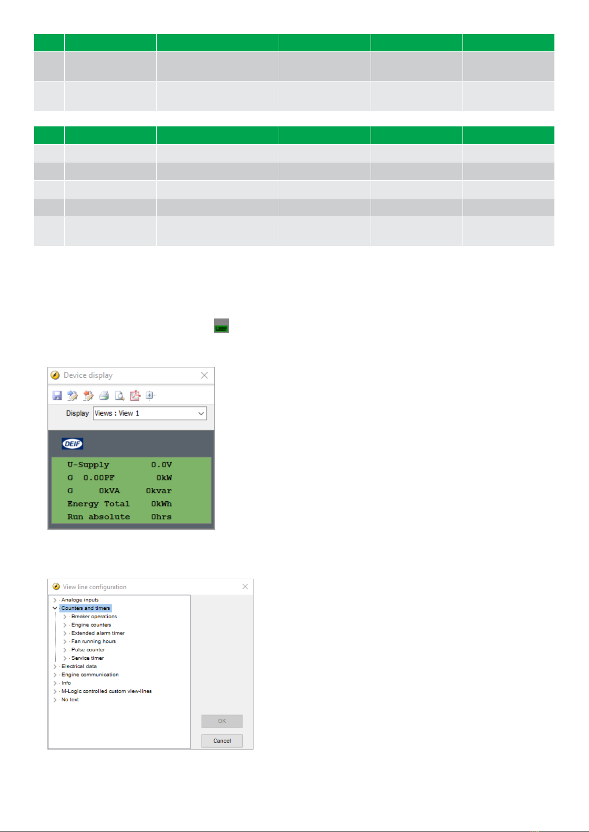
3.3.2 Display text
Configure the display views
You can configure the display views with the utility software:
1. Select the Configuration of the user views button in the toolbar.
2. In the pop-up window, select the display view you want to change.
3. Select the display line you want to change.
4. In the pop-up window, select the text you want and click OK.
OPERATOR'S MANUAL 4189341314A EN Page 13 of 19

Display text
You can select five of the display texts for each display view.
3.4 Status texts
Status text Condition
ACCESS LOCK The configurable input is activated, and the operator tries to activate one of the blocked keys.
Aux. test ##.#V ####s The battery test is activated.
COOLING DOWN ###s Cooling-down period is activated.
DG BLOCKED FOR START The generator has stopped and has active alarm(s).
EDG READY AUTO The controller is in auto mode and ready to start in case of blackout.
EDG READY SEMI The controller is in semi-auto mode and ready for external signals or operator input.
EDG RUNNING SEMI The genset is running in semi-auto mode. The breaker is open.
EMERGENCY SUPPLY The controller is in auto mode and supplying power from the emergency generator due to blackout
on the mains busbar.
EXT. STOP TIME ###s The extended stop timer is running.
FULL TEST ###.#min Test mode is activated and test timer counting down.
GB ON BLOCKED The generator is running, the GB is open and there is an active Trip GB alarm.
GB TRIP EXTERNALLY Some external equipment has tripped the breaker. An external trip is logged in the event log.
GEN. RUNNING LOCAL Genset running in local mode.
GEN. RUNNING REMOTE Genset running in remote mode.
GEN. SUPPLY LOCAL Genset is supplying busbar in local mode.
GEN. SUPPLY REMOTE Genset is supplying busbar in remote mode.
GENSET READY REMOTE The controller is in remote mode and ready to respond.
GENSET READY LOCAL The controller is in local mode and waiting for operator input.
GENSET STOPPING Cooling down has finished.
Hz/V OK IN ###s The voltage and frequency on the genset is OK. When the timer runs out the generator breaker can
be closed.
IDLE RUN The idle run input is active.
IDLE RUN ###.#min The idle run function is active. During a start the genset will not go to nominal RPMs. During a stop
the genset will not stop before the timer has expired.
ISLAND ACTIVE The controller is in remote mode and supplying power.
RUN COIL ON Run coil is active during the start sequence.
SHUTDOWN OVERRIDE The configurable input is active.
SIMPLE TEST ###.#min Test mode is activated and test timer counting down.
START DG(s) IN ###s The start genset set point has been exceeded. The genset will start when the timer expires.
START PREPARE The start prepare relay is activated.
START RELAY OFF The start relay is deactivated during the start sequence.
START RELAY ON The start relay is activated.
STOP DG(s) IN ###s The stop genset set point has been exceeded. The genset will stop when the timer expires.
TB TRIP EXTERNALLY Some external equipment (not the controller) has tripped the breaker. An external trip is logged in
the event log.
VOLT/FREQ OK IN ###s The voltage and frequency will be okay in ###s.
OPERATOR'S MANUAL 4189341314A EN Page 14 of 19
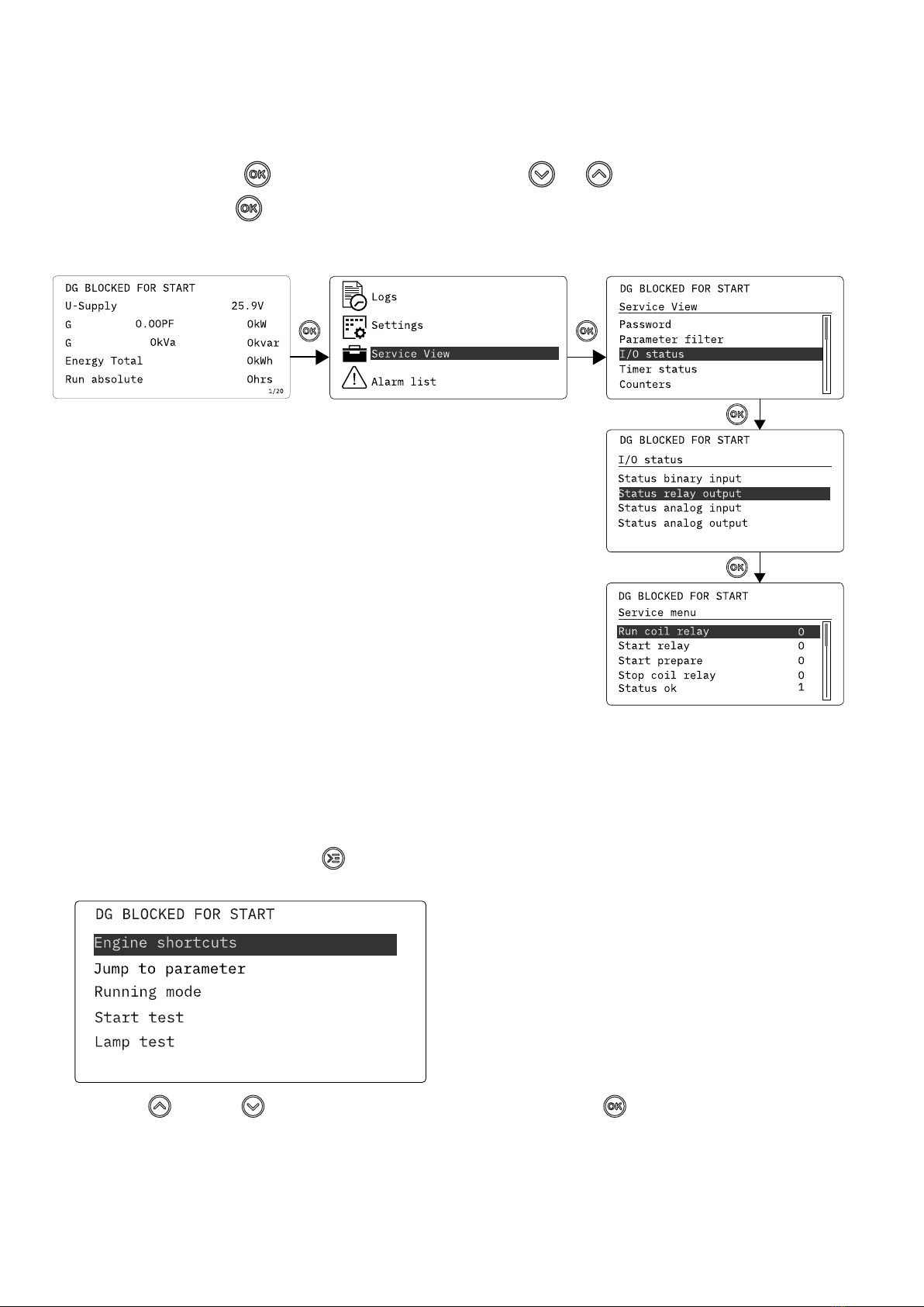
3.5 Service view
You can use the service view to see the status of the controller. You can change the passwords in the service menu, but not the
other controller settings.
From the view menu, push the button and select Service View . Use the and buttons to go through the parameters in
the service view, and use the button to select the parameters.
Service view example
Push
Push
Push
Push
3.6 Engine drive shortcut menu
The engine drive shortcut menu is used to configure the PID set points.
On the controller:
1. From the view menu, push the Shortcut button to see the menu.
2. Use the Up and Down buttons to go to Engine shortcuts menu, and push the button.
OPERATOR'S MANUAL 4189341314A EN Page 15 of 19

PID references:
• Only active inputs are shown in the list.
• You can also see the values in the utility software. Select PID on the horizontal panel to see the values. There are a total of 3
reference values.
Manual regulation (up and down)
• Used for PID1.
• Not active during ramp up/down.
3.7 Exhaust after-treatment (Tier 4/Stage V)
AGC 150 supports Tier 4 (Final)/Stage V requirements. It provides monitoring and control of the exhaust after-treatment system, as
required by the standard.
AGC 150 Tier 4/Stage V screen
DEF level: 32.0% 1/20
ISLAND SEMI
No. Referent Symbol Description
1. Engine emission system failure Shows an emission failure or malfunction.
2. Diesel Particle Filter (DPF) Shows that a regeneration is needed.
3. Application mode - -
4. Diesel Particle Filter (DPF) Inhibit Shows that regeneration is inhibited.
5. High temperature - Regeneration Shows a high temperature and regeneration is in process.
OPERATOR'S MANUAL 4189341314A EN Page 16 of 19
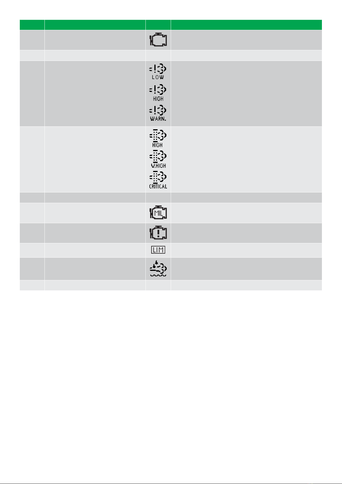
No. Referent Symbol Description
6. Engine interface status Shows an engine warning.
7. Operation mode - -
8. Engine emission system failure level Shows the severity of an emission failure or malfunction.
9. Diesel Particle Filter (DPF) level Shows the severity of a needed regeneration.
10. Page number - Shows the number of the View menu screen.
11. Engine interface status Shows a malfunction.
12. Engine interface status Shows an engine shutdown.
13. LIMIT lamp Only for MTU engines.
14. Diesel Exhaust Fluid (DEF) Shows the fluid tank level is low.
15. Diesel Exhaust Fluid (DEF) % level - Shows the level (%) of the Diesel Exhaust Fluid.
NOTE Grey symbols show that communication is available for the referent. An engine type might not support all of the referents.
OPERATOR'S MANUAL 4189341314A EN Page 17 of 19

4. Alarm handling and log list
4.1 Alarm handling
If the function Alarm Jump is on, the controller will automatically show the alarm list on the display screen when an alarm occurs.
Service View > Display > Alarm Jump
Parameter Text Range Default
9157 Alarm Jump OFF
ON ON
Access the alarm list from the display unit
1. From the view menu, push the button.
2. Use the and buttons to go to the Alarm list.
3. Push the button to view the Alarm list.
4. Push the button to go back.
The alarm list contains both acknowledged and unacknowledged alarms that are active. An alarm is active, if you have not cleared
the alarm condition, which started the alarm. Once an alarm is acknowledged and you have cleared the alarm condition, the alarm is
removed from the alarm list. If there are no alarms, then the alarm list will show No alarms.
The display screen can show only one alarm at a time. The number of alarms is shown on the right at the bottom of the screen.
Example of an unacknowledged alarm
To see the other alarms, use the and buttons to go through the list. To acknowledge an alarm, select the alarm and push
the button.
Access the alarm list with the utility Software
Select Alarms on the vertical panel on the left.
OPERATOR'S MANUAL 4189341314A EN Page 18 of 19

4.2 Logs menu
These are the log sub-menus:
1. Event log: Shows up to 500 events.
2. Alarm log: Shows up to 500 alarms. Only the latest 100 alarms are shown on the display unit, while the remaining alarms are
shown in the utility software.
3. Battery test log: Shows up to 52 tests, either Test OK or Test failed.
Access the log menu from the controller
1. From the view menu, push the button.
2. Use the and buttons to go to Logs.
3. Push the button to select Logs.
4. Select the log you want to see and push the button.
5. To leave the Log , push the button.
Access the log list with the utility software
1. In the vertical panel on the left, select Logs .
2. In the task bar, select Read logs .
3. Select the Log list you want to see.
OPERATOR'S MANUAL 4189341314A EN Page 19 of 19
Other manuals for AGC 150
9
Table of contents
Other Deif Marine Equipment manuals


Popular Marine Equipment manuals by other brands


Qlightec
Qlightec SMP35-N quick start guide

Kongsberg
Kongsberg cPAP MKII Quick reference guide

Marine PC
Marine PC MPC-ML2**R user manual

Teleflex Marine
Teleflex Marine CH2200ENC instructions

Siren Marine
Siren Marine SirenSat Offshore Installation & user guide

Craftsman Marine
Craftsman Marine SIRIUS manual


