CVS-705D/707D Contents
0092607052-03 v
Contents
Document Revision History.......................................................................................................................i
Important Notice.......................................................................................................................................ii
For Your Safe Operation .........................................................................................................................iii
Contents ...................................................................................................................................................v
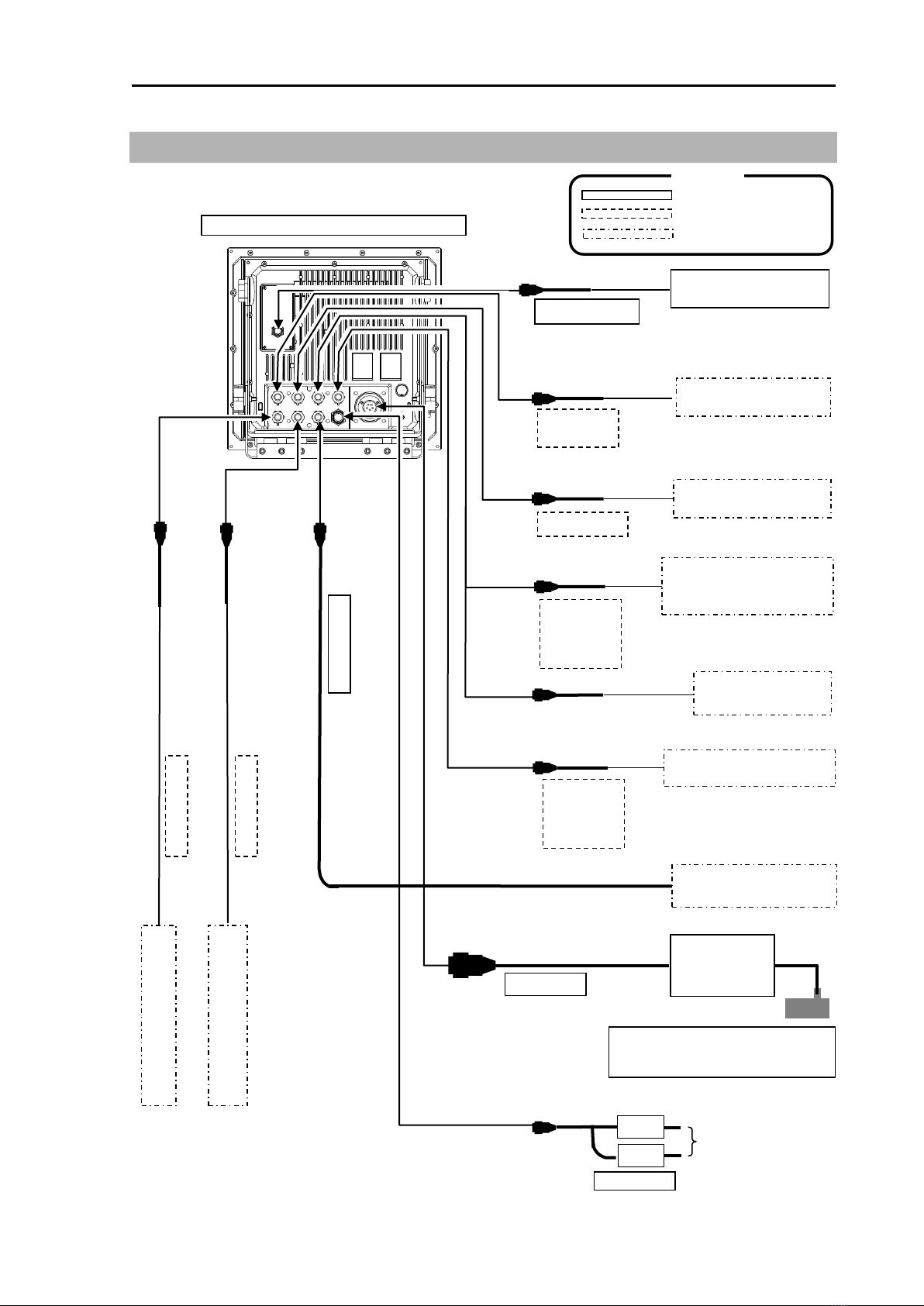
System Configuration.............................................................................................................................vii
Configuration of Equipment.....................................................................................................................ix
Dimensions............................................................................................................................................ xiii
Specifications ....................................................................................................................................... xvii
Chapter 1 Installation ……………………………………………………………….1-1
1.1 Installation precautions.............................................................................................................. 1-1
1.1.1 Unpacking of components.........................................................................................................1-1
1.1.2 Appearance verification of each unit and accessories..............................................................1-1
1.1.3 Selection of location for installation...........................................................................................1-1
1.1.4 Laying and connection of cables............................................................................................... 1-2
1.1.5 Coordination after installation.................................................................................................... 1-2
1.2 Installation of CVS-705D Display unit ....................................................................................... 1-3
1.2.1 Desk-top installation ..................................................................................................................1-3
1.2.2 Flush-mount installation.............................................................................................................1-5
1.3 Installation of CVS-707D Processor unit................................................................................... 1-6
1.4 Installation of 17 inch LCD Monitor (CVS-707D)....................................................................... 1-7
1.4.1 Desk-top installation ..................................................................................................................1-7
1.4.2 Flush-mount installation.............................................................................................................1-9
1.5 Installation of Operation unit....................................................................................................1-10
1.5.1 Desk-top installation ................................................................................................................1-10
1.5.2 Flush-mount installation...........................................................................................................1-12
1.6 Installation of transducer .........................................................................................................1-13
1.7Wiring.......................................................................................................................................1-15
1.7.1 Connection of cables to Display and Processor unit...............................................................1-15
1.8 Connection of Hemisphere V102 GPS Compass / ComNav Vector G1 GPS Satellite Compass
................................................................................................................................................1-27
1.8.1 Connection of Hemisphere V102 GPS Compass / ComNav Vector G1 GPS Satellite Compass
.................................................................................................................................................1-27
1.8.2 Setting of Hemisphere V102 GPS Compass / ComNav Vector G1 GPS Satellite Compass..1-32
1.9List of input/output sentences..................................................................................................1-38
1.9.1 Input sentence......................................................................................................................... 1-38
1.9.2 Output sentence ......................................................................................................................1-38
Chapter 2 Adjustment ……………………………………………………………….2-1
2.1 Setup of transducer................................................................................................................... 2-1
2.1.1 Setup of type of high frequency transducer...............................................................................2-1
2.1.2 Setup of type of low frequency transducer................................................................................2-1
2.2 Setup of frequency of transducer ..............................................................................................2-2
2.2.1 Setup of frequency for high frequency transducer ....................................................................2-2
2.2.2 Setup of frequency for low frequency transducer......................................................................2-3
2.3 Setup of Beam Angle of transducer........................................................................................... 2-3
2.3.1 Setup of Beam Angle for high frequency transducer................................................................. 2-3
2.3.2 Setup of Beam Angle for low frequency transducer ..................................................................2-4
2.4 Setup of Bottom Limit................................................................................................................2-4
2.4.1 Setup of Bottom Limit HF ..........................................................................................................2-4
2.4.2 Setup of Bottom Limit LF........................................................................................................... 2-5
2.5 Setup of Draft Set...................................................................................................................... 2-5
2.6 Setup of Gain (TD) for transducer.............................................................................................2-5
2.7Setup of Output Limit for transmitter .........................................................................................2-6
2.7.1 Display of Output Limit Menu ....................................................................................................2-6
2.7.2 Setup of Output Limit HF........................................................................................................... 2-6
2.7.3 Setup of Output Limit LF............................................................................................................2-7