Hattrick-Pro KP-1000 User manual
KP-1000 ELLIPTICAL BIKE USER MANUAL

1
CONTENT
PRODUCT SAFETY ---------------------------------------------------------- 2
HARDWARE & TOOLS------------------------------------------------------- 3
BOX CONTENTS ------------------------------------------------------------- 4
ASSEMBLY --------------------------------------------------------------------- 6
TROUBLESHOOTING & MAINTENANCE -------------------------------- 15
WARM UP -----------------------------------------------------------------------16
PART LIST------------------------------------------------------------------------17
EXPLODED VIEW --------------------------------------------------------------19

2
PRODUCT SAFETY
Basic precautions should always be followed, including the following safety instructions
when using this equipment: Read all instructions before using this equipment.
1.) Read all the instructions in this manual and do warm up exercises before using this equipment.
2.) Before exercise, in order to avoid injuring your muscles, warm-up exercise for every muscle
group is highly recommended. Please refer to the Warm Up pages for pre and post workout.
3.) Please make sure all components are not damaged and in working order before use.
This equipment should be placed on a flat surface while in use. Using a mat or other material on
the ground is recommended.
4.) Please wear proper clothes and shoes when using this equipment; do not wear clothes that
might catch in any part of the equipment.
5.) Do not attempt any maintenance or adjustments other than those described in this manual.
Should any problems arise, discontinue use and consult an Authorized Service Representative.
6.) Be careful when stepping on or leaving the pedals. Always hold the handlebars first and make
sure the pedal at your side is at its lowest position. Step on the pedal, and stride over the main
frame then step on the other pedal. When using, please hold onto the handlebars. To ensure
the pedals run smoothly push or pull on the handlebars first, then follow with leg motion.
When stepping off the machine, make sure one pedal is at its lowest position and step out of
there before stepping out of the pedal at the highest position.
7.) Do not use the equipment outdoors.
8.) This equipment is for household use only.
9.) Only one person should be on the equipment while in use.
10.) Keep children and pets away from the product while in use. This machine is designed for
adults only. If you feel any chest pains, nausea, dizziness, or short of breath, you should stop
exercising immediately and consult your physician before continuing.
11.) If you feel any chest pains, nausea, dizziness, or short of breath, you should stop exercising
immediately and consult your physician before continuing.
WARNING:Before beginning any exercise program consult your physician.This is
especially important for the persons who are over 35 years old or who have
pre-existing health problems. Read all instructions before using any fitness
equipment.

3
CAUTION:Read all instructions carefully before operating this product.Retain this
Owner’s Manual for future reference.
HARDWARE&TOOLS
Hardware & Tools (Pack A)
(B21/ 5) Screw M5x16mm---30pcs
(B23/ 2) Bolt M6x15mm---8pcs
(B28/ 1) Bolt M8x50mm---4pcs
(B29/ 3) Nylon Nut M8---4pcs
(B30/ 4) Curve Washer M8x20x1.5t---4pcs
(B40/ 10) Bolt M8x25mm---2pcs
(6) Hex Tool With Phillips Screwdriver(13mm/14mm)---1pc
(7) Allen Wrench(M4)---1pc
(8) Allen Wrench(M5)---1pc
Hardware & Tools (Pack B)
(B13/ 6) Bolt M8x16mm---16pcs
(B14/ 3) Bolt M8x20mm---4pcs
(B24/ 1) Bolt M8x92mm---2pcs
(B29/ 5) Nylon Nut M8---2pcs
(B30/ 4) Curve Washer M8x20x1.5t---16pcs
(B32/ 2) Hexagon Head Bolt M8x16mm---6pcs
(B33/ 7) Washer 5/16”x20x2.0t---8pcs

4
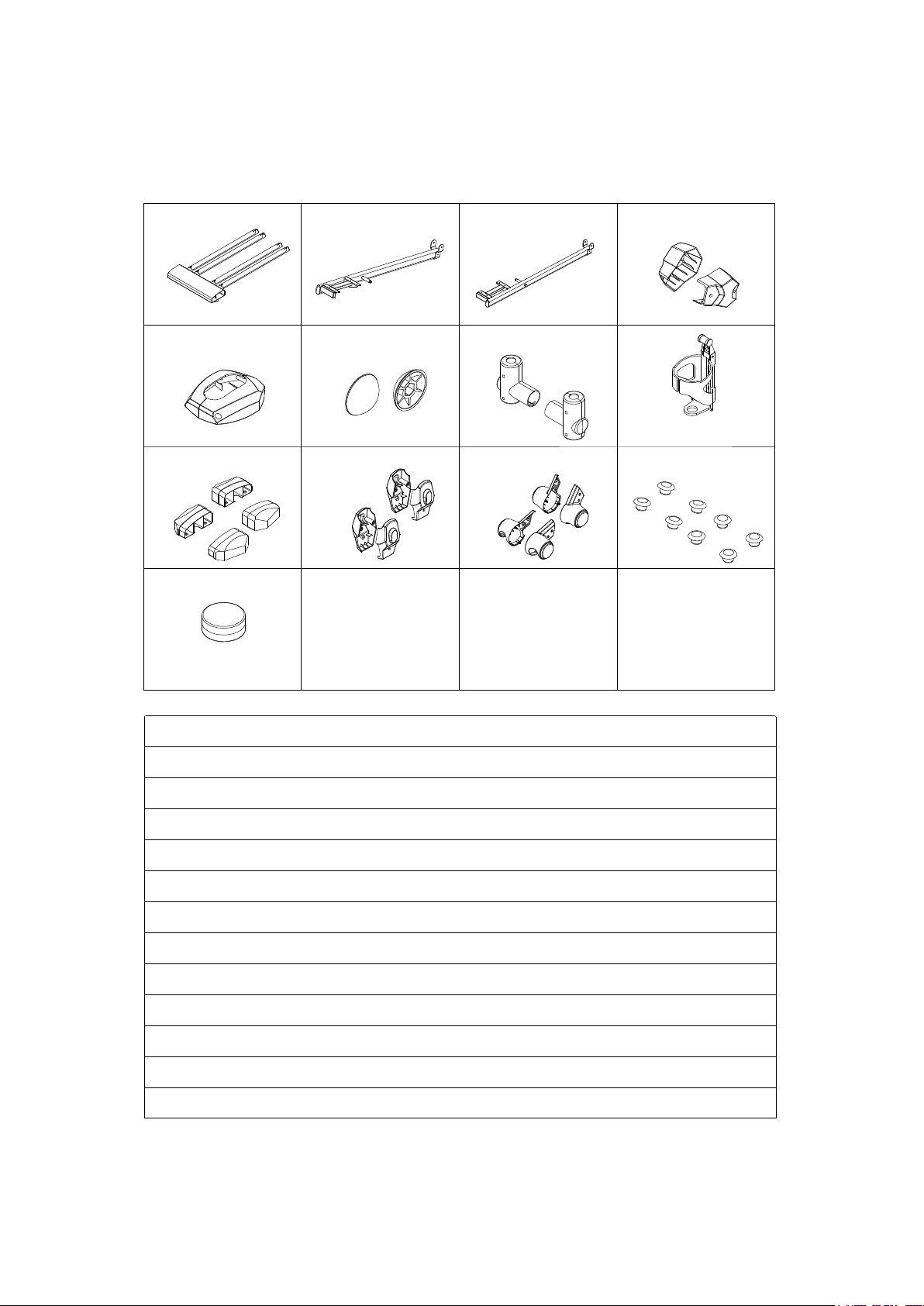
BOX CONTENTS
Box A Contents
Box Contents
A BOX CONTENTS
A01 A07 A08 A13/A14
A02 A15
D02C12
A03 A04
(A01) Main Body 1PC
(A07) Left Wheel Bar Set 1SET
(A08) Right Wheel Bar Set 1SET
(A13/A14) Handrails 1SET
(A02) Front Post 1PC
(A15) Hand Pulse Handlebar 1PC
(D02) Computer 1PC
(C12) Foot Pedal 2PCS
BOX CONTENTS
(A03) Left Dual Action Arm Set 1SET
(A04) Right Dual Action Arm Set 1SET
Water Bottle 1PC
5
Box B Contents
Box Contents
A12 A05 A06
C27C17/C18C11C07/C08
C28/C29 C32/C33C30/C31
C35
C34
(A12) Guide Rail 1PC
(A05) Left Foot Bar Set 1SET
(A06) Right Foot Bar Set 1SET
(C27) Bottle Holder 1PC
(C17/C18) Handrail Arm Decorative Covers-A/B 2SET
(C11) Nut Cap 2PCS
(C07/C08) Right/Left Front Post Decorative Covers 1SET
(C28/C29) Right/Left D Shape End Cap 2SET
(C32/C33) Right/Left Wheel Cap 2SET
(C30/C31) Right/Left Pivot Cap 2SET
(C35) Pivot Cap For Crank Link Tube 2PCS
(C34) Foot Pedal Plug 8PCS
Lubricant 1PC
BOX CONTENTS
Lubricant
B BOX CONTENTS
6
C29
C28
A12
B30
B30
B30
B30
B13
B13
C29
C28
A01
B13
B30
B13
C05
C05
C05
C05
C05
C05
A12
A01
Adjusting the Adjustable Leveler
A02
B14
B14
B14
B14
B14
D06
D04
D05 D07
D06
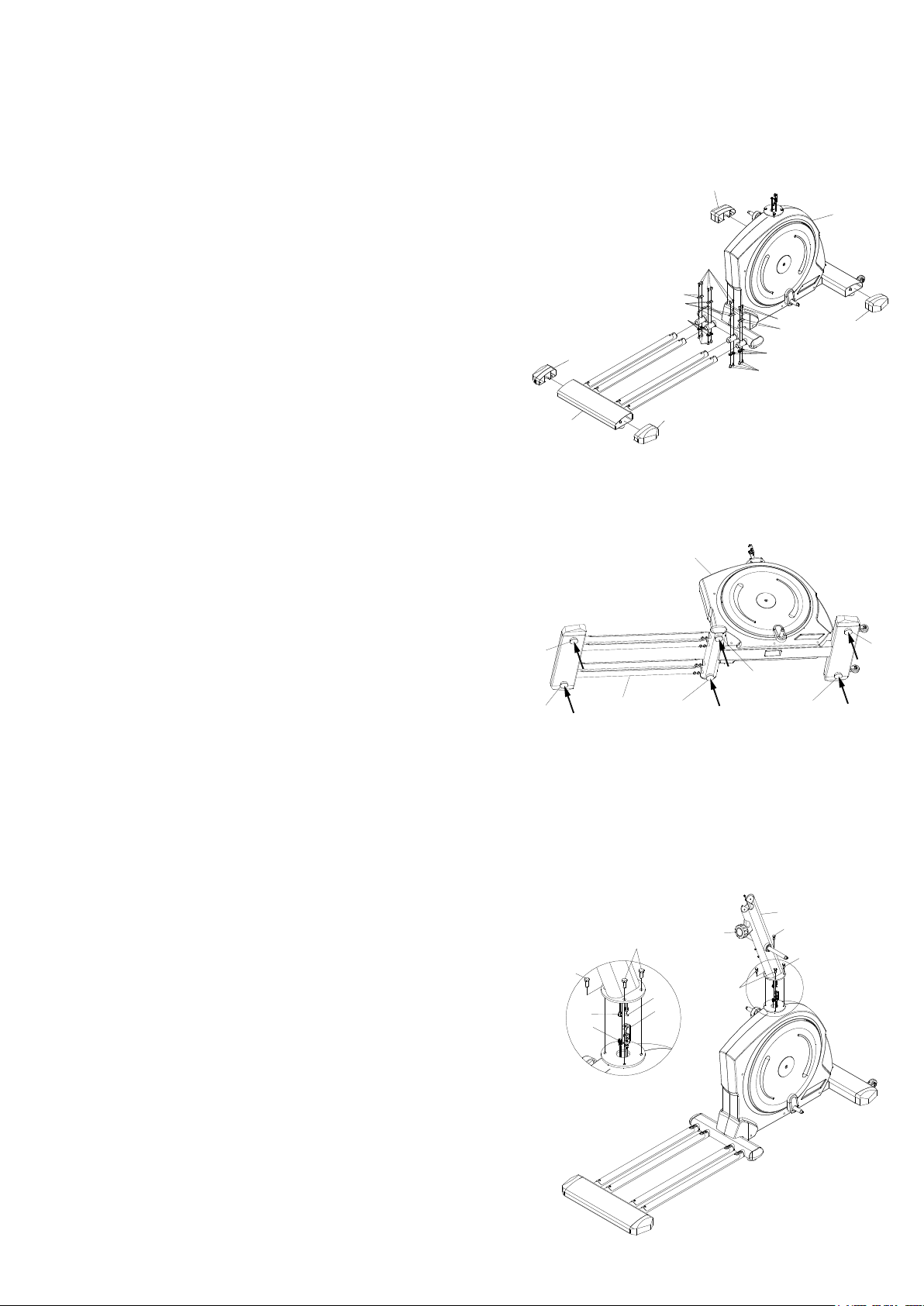
ASSEMBLY
Step1. RearStabilizer Installation
1.) Attach the Guide Rail (A12) onto the tubes of the MainBody(A01) with 16 Bolts
M8x16mm(B13) and 16 Washers M8x20x1.5t(B30) that were removed.
2.) Assemble the Left and Right D Shape End Cap(C28/C29) into the tube of
the MainBody(A01) and Guide Rail(A12).
[Remove/Tighten bolts with the M5 Allen Wrench provided]
Step2.Adjusting the Adjustable Leveler
1.) Turn the Adjustable Levelers(C05) on the MainBody(A01)
and Guide Rail(A12) as needed to level the elliptical
trainer.
The elliptical trainer has to be leveled to prevent from wobbling or shaking during the exercise.
Step3. Front Post Installation
1.) Connect the Sensor With Cable(D05) from the
MainBody(A01)to the Sensor Cable(D04) from the Front Post
(A02) andcarefully tuck the wires into the MainBody(A01)
before attachingthe Front Post (A02) onto the MainBody(A01).
2.) Attach the Front Post (A02) onto the MainBody(A01) and fullytighten with 4
Bolts M8x20mm(B14).

7
Lubricant
A02
A02
A11
A11
[Tighten bolts with the Hex Tool With Phillips Screwdriver provided]
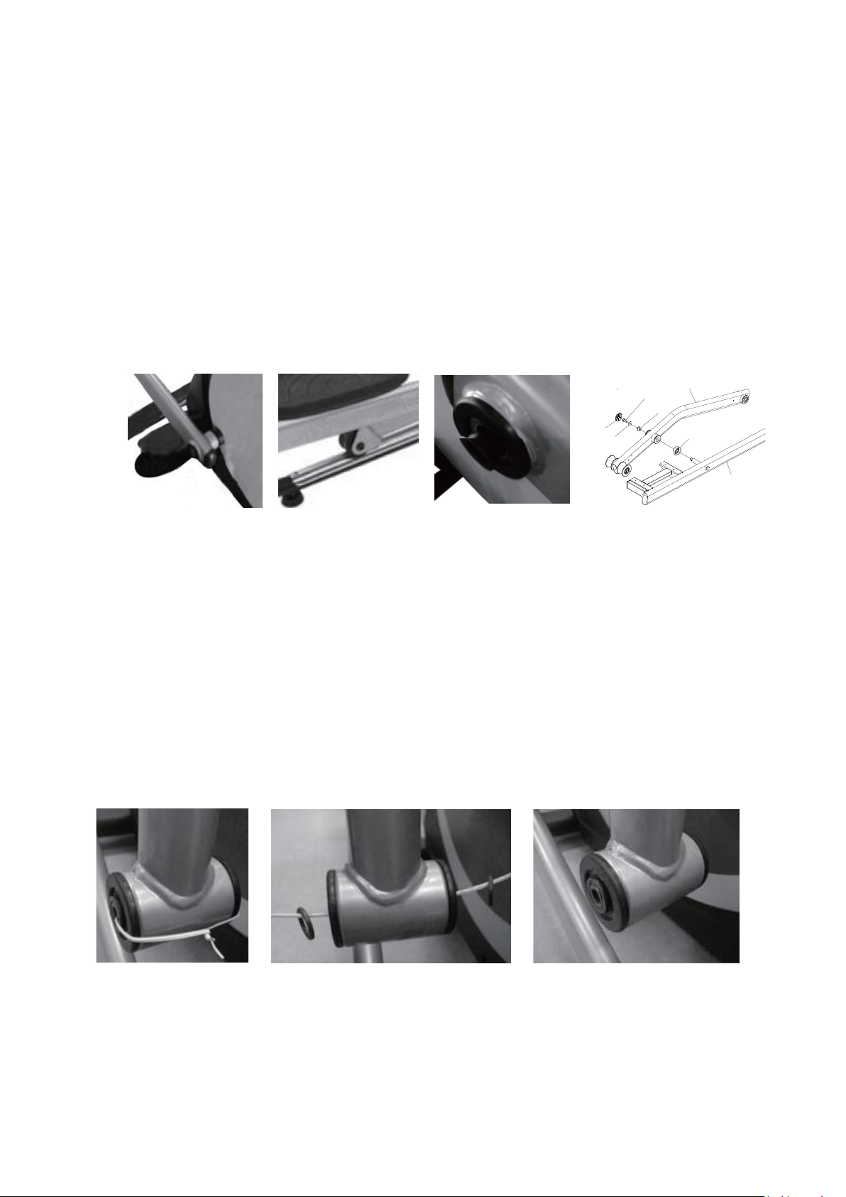
Step4. Lubricating the Horizontal Axle and Crank Axle
Apply lubricant to the horizontal axles of the Front Post (A02) and the axles of the right and left
Crank (A11).
Remark:Gently apply lubricant evenly on Front Post (A02).
Brush tool isrecommended.
Step5. Left and Right Foot Pedal Linkbar Installation
1.) Remove the tape from the joint of the Right Dual Action Arm Set (A04).
2.) Insert the Right Dual Action Arm Set (A04) all the way onto the horizontal axle of the Front Post (A02)
and secure the Right Dual Action Arm Set (A04) in position with 1 BoltM8x16mm(B32) and 1 Washer
5/16”x20x2.0t(B33).
[Tighten bolt with the Hex Tool with Phillips Screwdriver provided.]
Set the Tension Control Knob
(D06) to the highest level&
connect the Tension Cable
(D07).
8
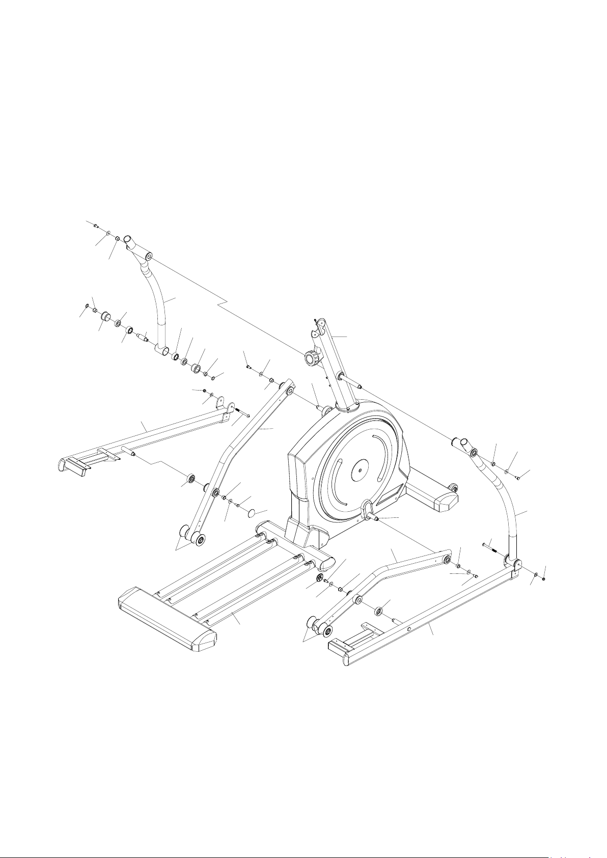
3.) Remove the tape from the joint of the Right Wheel Bar Set (A08).
4.) Insert the Right Wheel Bar Set (A08) onto the Crank (A11) axle.
5.) The Wheel (C20) has to be placed on the Rail Aluminum Plate (F01).
Secure the Right Wheel Bar Set (A08) in position with 1 Bolt M8x16mm(B32) and 1 Washer
5/16”x20x2.0t(B33).
6.) Insert the axle of the Right Foot Bar Set(A06) onto the Right Wheel Bar Set(A08), secure the
Right FootBar Set(A06) in position with 1 Bolt M8x16mm(B32) and 1 Washer
5/16”x20x2.0t(B33).
[Tighten bolt with the Hex Tool with Phillips Screwdriver provided]
CAUTION: Make Sure The Bushing Spacer (B41) Was Perfectly In Position Before Securing The
Bolts.
7.) Untie the wire and remove 2 Washers (C22) from the bottom end of the Right Dual Action Arm Set (A04).
Place 2 Washers (C22) back onto the joint of the Right Dual Action Arm Set (A04).
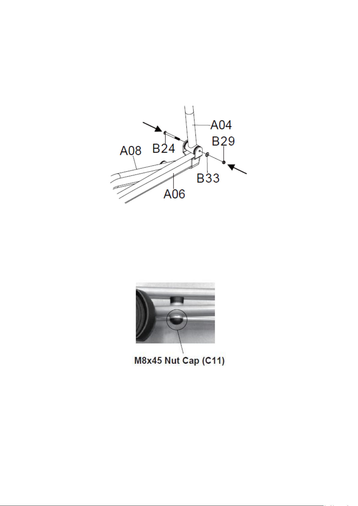
8.) Pull the Right Foot Bar Set (A06) up onto the Right Dual Action Arm Set (A04) and align bolt holes.
C11
B32
B33
B41
C23
A08
A06
9
Then attach the Right Foot Bar Set (A06) onto the Right Dual Action Arm Set (A04) with 1 Bolt
M8x92mm(B24),
1 Nut M8xP1.25x7.7t(B29), and 1 Washer 5/16”x20x2.0t(B33) that were removed.
[Tighten bolt and nylon nut with the Hex Tool with Phillips Screwdriver and M5 Allen
wrench provided]
9.) Fit one Nut Cap (C11) onto M8x16mm Hexagon Head Bolts (B32) of the Right Rotate Bar
(A08).
Repeat above steps to install the Left Dual Action Arm Set (A03) onto the horizontal axle of the Front Post (A02)
and Left Wheel Bar Set (A07) onto the Crank (A11) axle.
Remark: Please use the assembly drawings of steps No. 1-9 at Page No. 9.
10
A07
C23 B41
B33
B32
C11
B32 B33
B41
C11
B32
B33
B41
C23
A08 B41
B33
B32
A04
A06
B24
B33
B29
B32
B33
B41
A02
A05
A03
B32
B33B41
C25 E02
E02 C25
C24
C24 B31
C22
C22
B41
B41
B24
B29
B33
C20
F01
C20
A11
A11
11
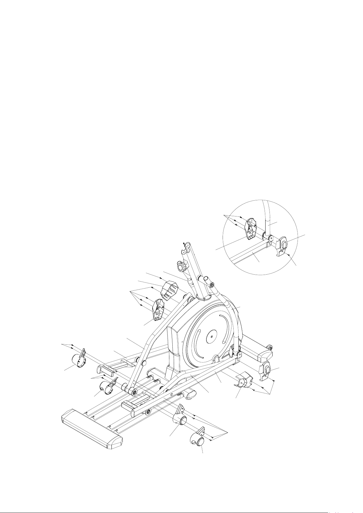
Step6. Pivot Covers Assembly
1.) Assemble two sets of Pivot Cover(C30/C31) at the pivot of Left and Right Dual Action Arm(A03/A04) and
Foot Pedal bar(A05/A06) with 8 Screws M5x16mm(B21).
2.) Assemble two pcs of Pivot Cover for Crank Link(C35) to the pivot of Right/Left Wheel Bar Set(A08/A07) and
Crank(A11) using 4 Screws M5x16mm (B21).
3.) Assemble two sets of Wheel Caps(C32/C33) to the wheel of the Left and Right Wheel Bar Set(A07/A08) with
8 Screws M5x16mm (B21).
[Tighten bolts with the Hex Tool With Phillips Screwdriver provided.]
I
C33
C32
C32
C33 B21
B21
B21
B21
B21
B21
C35
C35
C31
C30
C30
C31
B21
B21 A04
A07
A08
A04
A03 A06
A06
A05

12
B40
B40
A02
D08
D04
A15
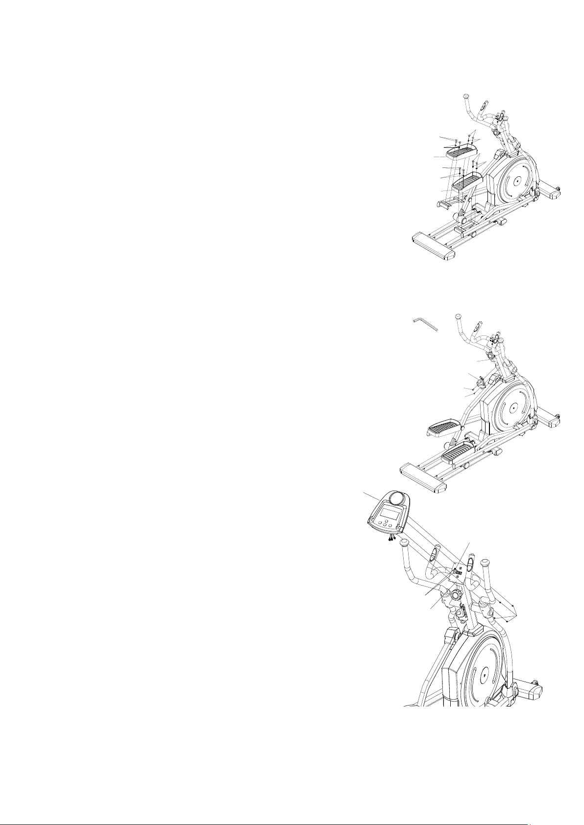
Step7. Hand Pulse Handlebar Installation
1.) Slide the Sensor Cable(D04) through the slot of Hand
Pulse Handlebar(A15), use 2 Bolts M8x25mm(B40) to
assemble the Hand Bar Post to the Front Post(A02).
[Tighten bolts with the M5 Allen Wrench provided.]
Step8. Right/Left Handrails Installation
1.) Slide the Left and Right Handrails(A13/A14) into the
Dual Action Tube.Use 4 Bolts M8x50mm(B28), 4 Curve
Washers M8x20x1.5t(B30) and 4 Nylon Nuts
M8x7.7t(B29).
[Tighten nylon nuts with the Hex Tool with Phillips
Screwdriver provided.]
B28 B28
B30
B30 B29
B29
A13 A14

13
C07
C08
B21
A02
Step9. Handrail Arm Decorative Covers-A/B Installation
1.) Attach the Handrail Arm Decorative Cover-A (C17) and Handrail
Arm Decorative Cover-B (C18) onto the Left Handrail Arm (A03)
with 4 Screws M5x16mm(B21).
2.) Attach the Handrail Arm Decorative Cover-A (C17) and Handrail
Arm Decorative Cover-B (C18) onto the Right Handrail Arm
(A04) with 4 Screws M5x16mm(B21).
[Tighten bolts with the Hex Tool with Phillips Screwdriver
provided]
Step10. Left/Right Front Post Decorative Covers
Installation
1.) Attach the Left/Right Front Post Decorative Covers
(C07/C08) onto theFront Post (A02) with 2 Screws
M5x16mm(B21).
[Tighten Screws with the Hex Tool with Phillips
Screwdriverprovided.]
C17
C18
B21
B21
B21
B21
C18
C17 A04
A03
14
D02
B17
D08
D04
A15
Step11. Foot Pedal & Pedal Plug Installation
1.) Use 8 Bolts M6x15mm(B23) to assemble the Left and Right Foot
Pedal(C12).
2.) Attach the 8 Foot Pedal Plugs(C34) onto the Foot Pedal(C12).
[Tighten bolts with the Hex Tool with Phillips Screwdriver provided.]
Step12. Bottle Holder Installation
1.) Remove 2 Bolts (B15) from the Front Post (A02).
2.) Attach the Bottle Holder (C27) onto the Front Post (A02) with 2 Bolts
(B15) that were removed.
[Remove/Tighten bolts with the M4 Allen Wrench provided.]
Step13. ComputerInstallation
1.) Remove 4 Screws (B17) from the back of the Computer
(D02).
2.) Connect the Sensor Cable (D04), Hand Pulse Sensor Wire
(D08) to the wires that comefrom the Computer (D02)
and then attach the Computer (D02) onto the top end of
the Hand Pulse Handlebar(A15) with 4 Screws (B17) that
were removed.
[Remove/Tighten bolts with the Hex Tool with Phillips Screwdriver provided.]
C27
B15
B15
Tool:
Allen Wrench (M4)
A02
C12
C12
B23
B23
B23
B23
C34
C34
C34
C34

15
TROUBLE SHOOTING
Computer not working correctly
Check to make sure the computer cable is connected securely.
The elliptical trainer wobbles when in use
Turn the adjustable leveler on the front stabilizer, main frame, Rare Stabilizer
asneeded to level the elliptical trainer.The elliptical trainer has to be leveled
toprevent from wobble or shaking during the exercise.
Squeaking noise when in use
The bolts may be loose on the elliptical trainer, please inspect the bolts and tighten the
loose ones.
No, inconsistent, or erratic heart rate reading
Always hold on to the handlebar grip sensors with two hands instead of just one.
Try to maintain moderate pressure while holding onto the hand pulse sensors.
Make sure that the wire connections for the hand pulse sensors are secure.
MAINTENANCE
Cleaning
The elliptical trainer can be cleaned with a soft cloth and mild detergent. Do not use
abrasives orsolvents on plastic parts. Please wipe your perspiration off the elliptical
trainer after each use.Be careful not get excessive moisture on the computer display
panel as this might cause an electricalhazard or electronics to fail.Please keep the
elliptical trainer, specially, the computer console, out ofdirect sunlight to prevent screen
damage. Please inspect all assembly bolts and pedals on the
machine for proper tightness every week.
Storage
Store the elliptical trainer in a clean and dry environment away from children.

16
WARM-UP
Quadriceps Stretch
With one hand against a wall for balance, reach behind
you and pullyour right foot up. Bring your heel as close
to your buttocks aspossible. Hold for 15 counts and
repeat with left foot up.
Inner Thigh Stretch
Sit with the soles of your feet together with your knees
pointing outward. Pull your feet as close into your groin
as possible.
Gently push your knees towards the floor. Hold for 10
counts.
Toe Touches
Slowly bend forward from your waist, letting you back and
shouldersrelax as you stretch toward your toes. Reach
down as far as youcan and hold for 15 counts.
Hamstring Stretches
Sit with your right leg extended. Rest the sole of your left
footagainst your right inner thigh. Stretch toward your
toe as far aspossible. Hold for 15 counts Relax and then
repeat with left legextended.

17
PART LIST
Part No
Description
Qty
Part No
Description
Qty
A01
Welded,main frame
1
B20
Philips Screw M5x0.8px40L
1
A02
Welded,Front Post
1
B21
M5 Sheet Metal Screw
55
A03
Welded,Dual Action Tube Left
1
B22
Zinc Plate
2
A04
Welded,Dual Action Tube Right
1
B23
M6 Allen Key Screw
8
A05
Welded,Foot Pedal Tube Left
1
B24
M8 Allen Key Screw
2
A06
Welded,Foot Pedal Tube Right
1
B25
M8 Black Nut
1
A07
Welded,Foot Tube Left
1
B26
M10 Lock Nut
3
A08
Welded,Foot Tube Right
1
B27
C Clip
1
A09
Welded,Tension Wheel Arm
1
B28
M8 Carriage Bolt
4
A10
Welded,Shaft Pulley
1
B29
M8 Lock Nut
6
A11
Welded,Crank Assembly
2
B30
M8 Curve Washer
24
A12
Welded,Guide Rails Tube
1
B31
Shaft for Dual Action Arm Pivot
2
A13
Dual Action Handlebar Left
1
B32
M8 Hex Head Screw
10
A14
Dual Action Handlebar Right
1
B33
5/16" Washer
8
A15
Welded,Hand Pluse Handlebar
1
B34
M10 Hex Head Screw
2
B01
1/4”Hex Bolt
2
B35
M8 Allen Key Screw
4
B02
1/4”Washer
4
B36
5/16" Washer
4
B03
1/4”Lock Nut
2
B37
3/16" Sheet Metal Screw
1
B04
3/8"Nut
2
B38
M3 Sheet Metal Screw
2
B05
M6 Screw
2
B39
M4 Sheet Metal Screw
2
B06
C Clip
1
B40
M8 Screw
2
B07
Wave Washer
2
B41
Bushing Spacer
10
B08
M20 Washer
1
B42
M5 Sheet Metal Screw
2
B09
38 Washer
1
C01
Main Cover- Right
1
B10
M8 Hex Head Screw
1
C02
Main Cover- Left
1
B11
M10 Allen Key Screw
1
C03
Disc Cover
2
B12
M3 Sheet Metal Screw
2
C04
End Cap for Stabilizer Bar
2
B13
M8 Allen Key Screw
20
C05
Height Adjuster
6
B14
M8 Hex Head Screw
4
C06
Transportation Wheel
2

18
B15
M5 Allen Key Screw
2
C07
Upright Joint Cover Left
1
B16
M8 Screw
2
C08
Upright Joint Cover Right
1
B17
Screws for Computer
4
C09
End Cap for Foot Pedal Tube
2
B18
Tension Adjustment Screw
2
C10
Belt
1
B19
M6 Lock Nut
2
C11
Nut Cap
2
Part No
Description
Qty
Part No
Description
Qty
C12
Foot Pedal
2
C32
Wheel Cap L
2
C13
Foam Grip
2
C33
Wheel Cap R
2
C14
Plug
2
C34
Foot Pedal Plug
8
C15
Foam Grip
2
C35
Pivot Cap for Crank Link Tube
2
C16
Square End Cap 20x40
2
C36
Small Crank Decorated Cover
2
C17
Pivot Cover L
2
C37
Dual Action Arm Plug
2
C18
Pivot Cover R
2
D01
Hand Pulse Sensor
1Set
C19
Pulley
1
D02
Computer
1
C20
Roller
4
D03
Magnetic Flywheel
1
C21
Upright Tube Spacer
2
D04
Sensor Cable
1
C22
Washer
4
D05
Sensor With Cable
1
C23
Spacer
2
D06
Tension Adjuster With Cable
1
C24
Bearing Bushing
10
D07
Tension Cable
1
C25
Bearing Housing
10
D08
Hand Pulse Cacle
1Set
C26
Bushing
6
E01
Bearing 6004
2
C27
Water Bottle Holder
1
E02
Bearing 6003
10
C28
D Shape End Cap for Stabilizer
Bar L
2
E03
Bearing 6902
8
C29
D Shape End Cap for Stabilizer
Bar R
2
E04
Bearing 6203
2
C30
Pivot Cap L
2
F01
Aluminum Guide Rails
4
C31
Pivot Cap R
2
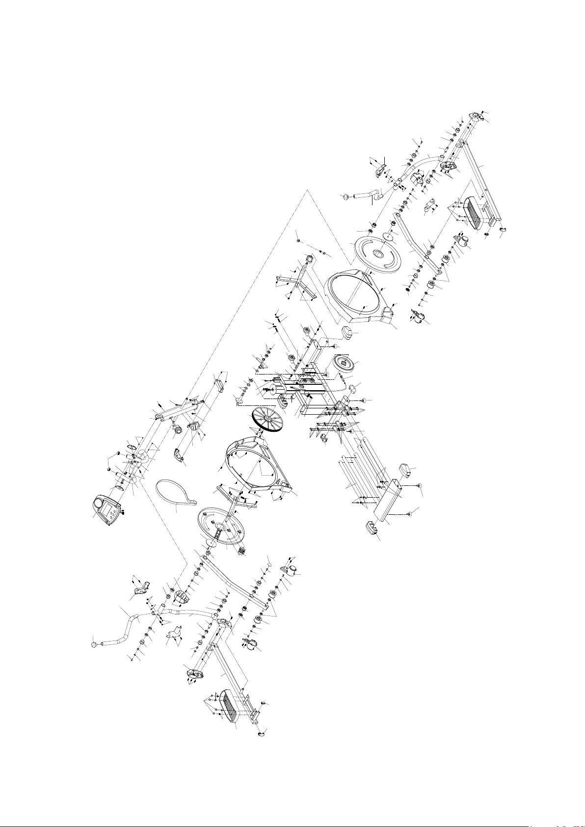
19
EXPLODED DIAGRAM
B21
E03 E03
B36B32
C20
C30
B21 C35
B21
C35
C28
C29
C28
C29
B21
B21
C33
C32
C33
C32
B21
B21
A04
A03
A12
A11
A09
A08
A07
A01
B39
E01
B11
C05
B26
B09
C05
B05
B18B19
B21
B21
B38
B37
B21
B21
B21
B21
B21
B21
C20
E03
B36
B32
B13
E01 B06
B30 B13
B13
F01
C25
C05
C04
C05
B41
B32
B33
B29
B30
B28
B21
B21
B32
B36
B32
B36
E03
C20
E03 E03
C20
B07
B08
C05
C25
E02
C24
B41
B33
B32 B21
B21 B28
B30B29
C06
B01
B03 C06
B01
B02
B02
B02
B02
B21
B26
B34
B26
B34
B32
B32
B32
B33
B33 B33
B32
B35
E02
E02
E02
E02
E02
E02
E02 E02
E02
B22
B22
D05
D07
D05
D03
B25
B05
B19
C26
C26
C26
C26
C25
C25
C25
C25
C25
C25
C25 C25
C24
C24
C24
C24
C24
C24
C24
C24 C24
C23
C23
B16
B16
B31
B31
B13
B10
B18
B04
E04
B04 B27
A10
C22
C22
C22
C22
B41
B41
B41
B41 B41 B41
B41
B41
C19
F01
C17
C18
C17
C18
C11
C11
C10
C08
C07
C03
C03
C01
C02
C04
B33
D02
D01
D01
C14
C13
C13
B12A15
B17
B17
D08
B40
B40
D08
D08
B14 B14
B14
A02
C27
B15
D04
C26
C26
B21
C09
C12
B23
B23
A06
B33B29
B24
C31 B21
C30
B21
A14
C15
C15
A13
C12
A05
C09
B24
B33
B29
B23 B23
B21
C31
B30
C16
C16
C21
C21
C37
C37
B21
B21
A11
B21
B21
B21
B42
B42
C36
C36
B13
B30
B13
C34
B30
B30
D06
D07
B20
C34 D06
D04
Table of contents


