Haul-All Equipment SURE FLAME S100 Installation and user guide
PRODUCTS
Rev: 2.11 March 12, 2008
SERVICE AND MAINTENANCE MANUAL No. 934-6891
PLEASE RETAIN FOR FUTURE REFERENCE
A Division of Haul-All Equipment Ltd.
4115 - 18 Avenue North
Lethbridge, Alberta T1H 5G1
www.sureflame.ca
CONSTRUCTION HEATER
S100
Page LM P/N: 934-6891 S100 Manual, Rev: 2.1.1
S100 CONSTRUCTION HEATER
Failure to comply with the precautions and instructions
provided with this heater, can result in death, serious
bodily injury and property loss or damage from hazards
of fire, explosion, burn, asphyxiation, carbon monoxide
poisoning, and/or electrical shock.
Only persons who can understand and follow the
instructions should use or service this heater.
If you need assistance or heater information such as
an instruction manual, labels, etc. Contact the
manufacturer.
Fire, burn, inhalation, and explosion hazard. Keep solid
combustibles, such as building materials, paper or
cardboard, a safe distance away from the heater as
recommended by the instructions. Never use the heater
in spaces which do or may contain volatile or airborne
combustibles, or products such as gasoline, solvents,
paint thinner, dust particles or unknown chemicals.
Not for home or recreational vehicle use
WARNING
WARNING
GENERAL HAZARD WARNING

S100 Manual, Rev: 2.1.1 P/N: 634-6891 Page RM
READ THIS
WARNING
FIRST !
The heater is designed and approved for use as a construction heater
under CSA 2.14-2000 and ANSI Z83.7-2000. The primary purpose of
construction heaters is to provide temporary heating of buildings
under construction, alteration, or repair and to provide temporary
emergency heat. Properly used the heater provides safe economical
heating. Products of combustion are vented into the area being
heated.
The heater is not designed as an Unvented Gas Fired Room Heater
under ANSI-Z21.11.2 and should not be used in the home.
ANSI A119.2(NFPA 501C)-1987 Recreational Vehicle Standard
prohibits the installation or storage of LP-Gas containers even
temporarily inside any recreational vehicle. The standard also prohib-
its the use of Unvented Heaters in such vehicles.
Gas inspection authorities in Canada require that the installa-
tion and maintenance of heaters and accessories be accom-
plished by qualified gas fitters.
Installation must comply with local codes, or in the absence of
local codes, with the Natural Gas and Propane Installation Code
CSA-B149.1, the National Fuel Gas Code ANSI Z223.1/NFPA 54
and the Standard for the Storage and Handling of Liquified
Petroleum Gases ANSI/NFPA 58.
We cannot anticipate every use which may be made for our heaters.
CHECK WITH YOUR LOCAL FIRE SAFETY AUTHORITY IF YOU
HAVE QUESTIONS ABOUT LOCAL REGULATIONS.
Other standards govern the use of fuel gases and heat producing
products in specific applications. Your local authority can advise you
about these.

Page LM P/N: 934-6891 S100 Manual, Rev: 2.1.1
FOR YOUR SAFETY
DO NOT USE THIS HEATER IN A SPACE WHERE
GASOLINE OR OTHER LIQUIDS HAVING
FLAMMABLE VAPOURS ARE STORED OR USED.
S100 CONSTRUCTION HEATER
CONTENTS
Specifications .......................................................................................... 5
Installation ............................................................................................... 6
Installation Using A Propane Supply Tank ................................................ 7
Installation For Natural Gas Applications ................................................. 7
Operating Instructions ............................................................................. 8
Sequence Of Operation ........................................................................... 8
Common Installation And Operational Problems ..................................... 9
Safety Features ....................................................................................... 9
Design Related Additional Safety Features ............................................ 10
On-site Safety Problems ........................................................................ 10
Preventative Maintenance ..................................................................... 11
S100 Heater Parts ................................................................................. 12
S100 Connection Wiring Diagram ......................................................... 14
S100 Ladder Wiring Diagram ................................................................ 15

S100 Manual, Rev: 2.1.1 P/N: 634-6891 Page RM
SPECIFICATIONS
Model No. S100 Construction Heaters
CSA Certified to CSA 2.14-2000 and ANSI Z83.7-2000 Gas Fired
Unvented Construction Heater
Gases: Natural or Propane
Capacity: 100,000 Btu/h (29 kW) maximum
Orifice Size: 43 DMS (x10)
Blower: 1,300 cfm (615 l/s)
Electrical Rating: 115 volts, 60 Hz., 4 amps, single
phase
Gas Supply:
Inlet Pressure Manifold Pressure
Max. W.C. Min.W.C. Max.W.C.
Propane 14" (3.5 kPa) 5" (1.25 kPa) 0.4" (100 Pa)
Natural 14" (3.5 kPa) 5" (1.25 kPa) 1.1" (275 Pa)
(Minimum inlet pressure is for purpose of input adjustment)

Page LM P/N: 934-6891 S100 Manual, Rev: 2.1.1
INSTALLATION
The Sure Flame Model S100 Construction Heater is a direct fired gas heater
intended to be used primarily for the temporary heating of buildings under
construction, alteration, or repair. Since all the products of combustion are
released into the area being heated, it is imperative that adequate ventilation
is provided. The flow of supply air and combustion gases must not be
obstructed in any way. Do not use the heater with ductwork as this will restrict
the flow of supply air.
1 Install the heater in a horizontal position at least 10 feet (3m) in
Canada or 6 ft. (1.83 m) in the U.S. from any LP-gas container. Allow
the following clearances from any combustible materials:
Front Outlet: 8 feet (2.4 m) Sides: 2 feet (0.6 m)
Intake: 2 feet (0.6 m) Top: 4 feet (1.2 m)
Front Outlet must not be directed at any LP-gas container within 20
feet (6 m).
Also make sure that no flammable vapours are present in the space
where the heater is being used.
2 When connecting the heater to a natural gas or propane supply line
ensure that the pressure at the heater inlet is within the specified range.
Excessive pressure (over 1/2" psi) will damage the controls and void the
warranty.
3 Visually inspect the hose assembly and ensure that it is protected from
traffic, building materials, and contact with hot surfaces. If it is evident that
there is excessive abrasion or wear, or the hose is cut, it must be replaced.
4 After installation, check the hose assembly for gas leaks by applying a
water and soap solution to each connection.
5 Connect the heater to an adequate 115 volt electrical supply as specified
on the rating plate. For protection against shock hazard the supply cord
must be plugged directly into a properly grounded three-prong recepta-
cle.
6 In all applications, install the heater in such a manner that it is not
directly exposed to water spray, rain and/or dripping water.

S100 Manual, Rev: 2.1.1 P/N: 634-6891 Page RM
INSTALLATION USING A
PROPANE SUPPLY TANK
1 When installing the heater for use with propane gas, set the gas selector
valve to “Propane”.
2 Arrange the propane supply system to provide for vapour withdrawal from
the operating container. Supplying liquid propane to the heater is danger-
ous and will damage the components. Another regulator must be
installed on the heater to reduce the pressure from this regulator to a
maximum inlet pressure of 1/2 psi.
3 Ensure that for the surrounding temperature the size and capacity of the
propane supply container is adequate to provide the rated Btu/h input to
the heater.
4 Turn off the propane supply valve at the container when the heater is not
in use.
5 The installation must conform with local codes, or in the absence of local
codes, with CSA-B149.1 Natural Gas and Propane Installation Code or
with the Standard for the Storage and Handling of Liquedied Petroleum
Gases, ANSI/NFPA 58.
6 When the heater is to be stored indoors the propane container must be
disconnected from the heater and the container moved away and stored
in accordance with the above National Standard.
INSTALLATION FOR
NATURAL GAS APPLICATIONS
1 When installing the heater for use with natural gas, set the gas selector
valve to the “Natural” position.
2 A regulator must be installed on the heater to ensure that the pressure to
the heater does not exceed 1/2 psi inlet pressure.
3 The installation of this heater to a natural gas supply must conform with
all applicable local codes, or in the absence of local codes, with CSA-
B149.1 Natural Gas and Propane Installation Code or with the National
Fuel Gas Code ANSI Z223.1/NFPA 54.

Page LM P/N: 934-6891 S100 Manual, Rev: 2.1.1
OPERATING INSTRUCTIONS
1 Set GAS SELECTOR VALVE to gas being used. The conversion shall
be done by the owner or lessor of the equipment.
NOTE: When using Propane Gas the Selector Valve must be in the
PROPANE position.
2 Ensure the MANUAL VALVE (blue knob at rear of heater) is in the “ON”
position.
3 Connect power - 115 volt supply.
4 Open gas supply.
5 Push START button AND HOLD FOR 5 SECONDS
6 To stop, turn gas off.
The appliance area should be kept clear and free from combustible materi-
als, gasoline, and other flammable vapours and liquids.
Ensure that the flow of supply air and combustion gases is not obstructed.
The installation and operation of the heater shall comply with the code
requirements specified by the authorities having jurisdiction.
General criteria for the use of construction heaters may be found in the
applicable sections of the Natural Gas and Propane Installation Code CSA-
B149.1.
THE INSTALLATION AND MAINTENANCE OF THE
HEATER MUST BE ACCOMPLISHED BY A
QUALIFIED SERVICE PERSON.
SEQUENCE OF OPERATION
1 Push start button AND HOLD FOR 5 SECONDS.
2 Relay closes.
3 Fan starts.
4 Fan reaches full speed and air switch closes.
5 Gas valve opens.
6 Spark is generated.
7 Flame rod senses flame, and then maintains flame.

S100 Manual, Rev: 2.1.1 P/N: 634-6891 Page RM
COMMON INSTALLATION AND
OPERATIONAL PROBLEMS
1 LOW VOLTAGE
This is one of the most common problems and is usually the result of the
supply cord having too small a wire gauge for its length. Low voltage
results in the motor overheating, burnt relay contacts, or a relay that will
not maintain contact.
2 SUPPLY LINE TOO SMALL
3 INSUFFICIENT VAPORIZATION AT SUPPLY
Normally caused by too small size of supply tank.
4 IMPROPER GAS SUPPLY PRESSURE
Usually a result of supply pressure being too high because of improper or
lack of regulation.
5 DIRTY GAS SUPPLY
Dirty gas can cause strainers to plug or form a build-up in the burner
orifice.
6 LACK OF PREVENTATIVE MAINTENANCE
Heaters must be cleaned as required, especially when used in a dirty
environment.
7 IMPROPER SUPPLY OF FRESH AIR
It is normally recommended that the intake air of the heater be taken from
outside the enclosed area. This provides a slight pressurization and
prevents any problems associated with recirculation.
SAFETY FEATURES
The Model S100 incorporates devices to detect the following:
1 LOSS OF FLAME Gas supply is shut off if flame is lost to
prevent raw gas from leaving the heater.
2 OVERHEATING High temperature limit switch in the com-
bustion chamber
3 LOSS OF POWER Total shutdown with manual restart re-
quired. Any one of the safety devices will
create a loss of power situation.
4 BLOCKED AIR SUPPLY A switch detects the differential pressure
in the combustion chamber and shuts down
when insufficient.

Page LM P/N: 934-6891 S100 Manual, Rev: 2.1.1
DESIGN RELATED ADDITIONAL
SAFETY FEATURES
1 LOW SKIN TEMPERATURE
Sure Flame Heaters are designed to have a low skin temperature. This
provides added safety in the workplace.
2 DURABLE CONSTRUCTION
The Model S100 uses a stainless steel burner for long life and consistent
performance.
In order to maintain the highly efficient combustion of the Sure Flame
Heater, the combustion chamber must remain as manufactured. Any
change or distortion could alter the fuel/air mixture and create unwanted
gases.
ON-SITE SAFETY PROBLEMS
1 SHORTING OUT OF DEFECTIVE COMPONENTS
This common problem saves short term expense at the risk of a large
future cost. Any heaters found in this condition should be removed
immediately.
2 IMPROPER ENCLOSURES
When heaters are installed partially to the outside for fresh air intake, strict
adherence must be made to the minimum clearance to combustibles
given on the instruction plate. Wood framing around a heater is a request
for trouble.
3 SUPPLYING LIQUID PROPANE TO HEATER
This problem has occurred from time to time. To minimize the damage,
and possible personal injury, shut off the gas supply and let the heater run
until all of the liquid in the lines has been vaporized.

S100 Manual, Rev: 2.1.1 P/N: 634-6891 Page RM
PREVENTIVE MAINTENANCE
Sure Flame Construction Heaters are built to withstand the rigours of
operating on construction sites, for mining applications, and a multitude of
other locations where heaters are used. To maintain the reliable perform-
ance required it is necessary to do a certain amount of regular maintenance.
A VISUAL CHECKS
The following items should be checked for excessive wear or damage:
1) Cords and Connectors
2) Wiring and Conduit
3) Heater Shell (including heat shield) and Control Box
It is recommended that units purchased as spares be rotated periodi-
cally, so that each unit will be placed in operation at least once every 90
days.
B BURNER
Flame Rod and Insulator - Clean with soap and water or solvent on a
routine basis. Any build up on burner
should also be removed at this time.
Spark Plug - Clean with solvent and check spark gap.
C CONTROL BOX
The inside of the control box should be cleaned using a dry cloth or by
blowing compressed air. Do not use any liquid or aerosol spray cleaners.
Also check that all electrical connections are snug and tight.
D MOTOR
The electric motor on the S100 Heater is fitted with sealed bearings and
no oiling is required. Keep the motor clean by blowing or wiping off dust
or dirt in order to prevent it from over heating.
E FAN
Check for dust or dirt build up on fan blades. Check the tightness of the
set screw and run the heater to check for fan vibration.
Page LM P/N: 934-6891 S100 Manual, Rev: 2.1.1
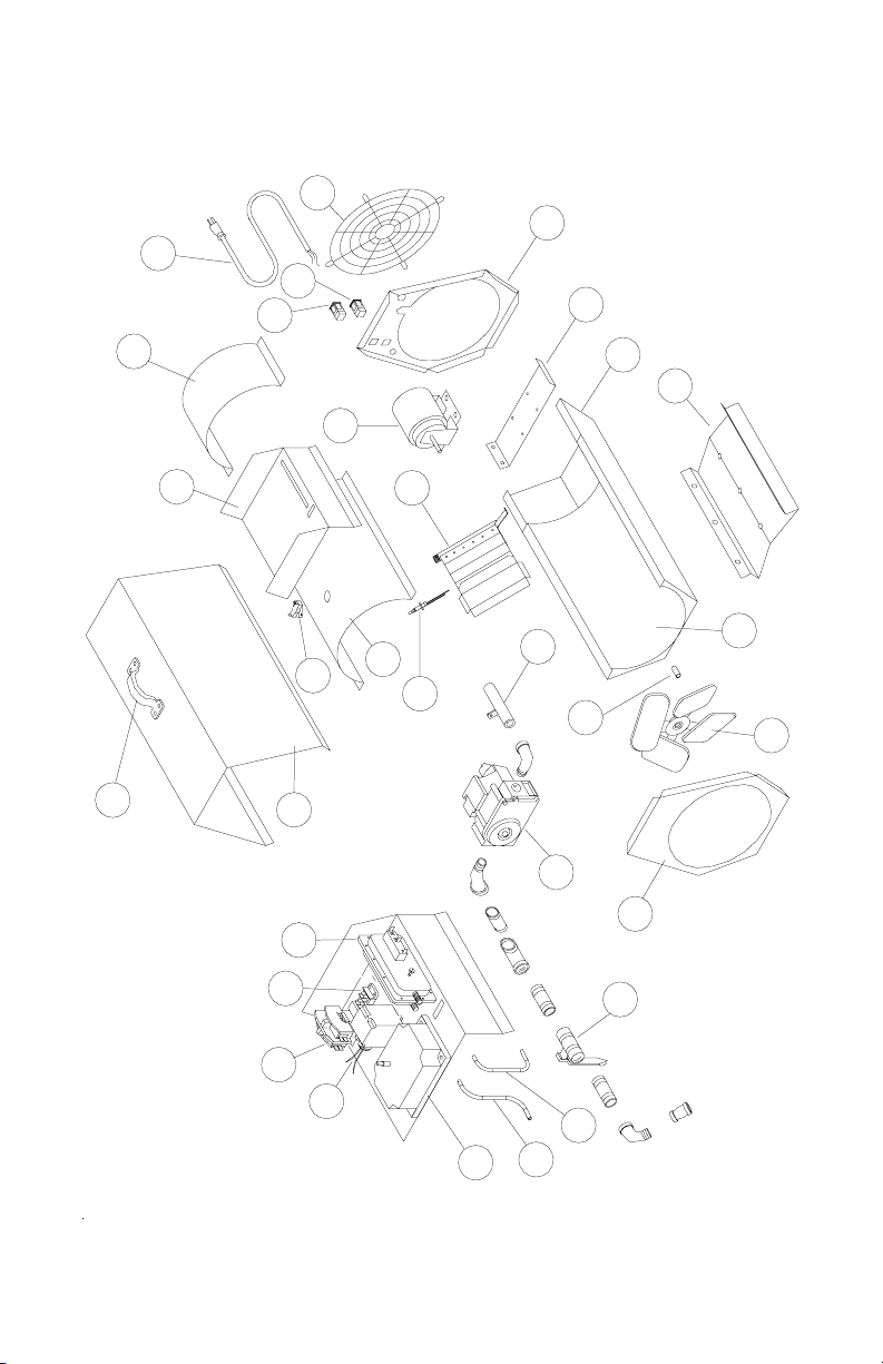
S100 HEATER PARTS
22
17
16
12
13
14
1
2
19
11
3
5
6
7
4
15
18
20
21
29
26
23
28
30
27
25
10
24
8
9
32
September 13, 2002

S100 Manual, Rev: 2.1.1 P/N: 634-6891 Page RM
S100 HEATER PARTS
Sept. 13, 2002
Ref. Part No Description
1 6897 Handle
2 S100-101 Top Shell
3 5124 Air Switch (0.2" W.C.)
4 5768 Terminal Block
5 4519 Motor Relay 24V
6 4511 Transformer 24V
7 8264 Direct Spark Ignition Control
8 S100-716 Downstream Airtube “S”
9 S100-715 Upstream Airtube “C”
10 S100-115 Front Top Heat Shield
11 2446 HI Limit Switch
12 S100-110 Control Box
13 S100-116 Top Rear Heat Shield
14 3868 24" Power Cord
15 S100-717 S100 Fan Guard
16 3337/8 OFF Switch (Red)
17 3337/9 ON Switch (Green)
18 S100-106 Rear End Panel
19 6892 1/8 HP Motor
20 S100-107 Motor Mount
21 S100-102 Bottom Shell
22 BV2-502 Burner
23 6894 Triple Electrode
24 S100-109 Base
25 S100-103 Bottom Heat Shield
26 6901 Shaft Adapter
27 2419 Fan Blade
28 S100-105 Front End Panel
29 6895 Gas Valve
30 S100-707 Changeover Valve
32 S100-501 Pipe Weldment

Page LM P/N: 934-6891 S100 Manual, Rev: 2.1.1
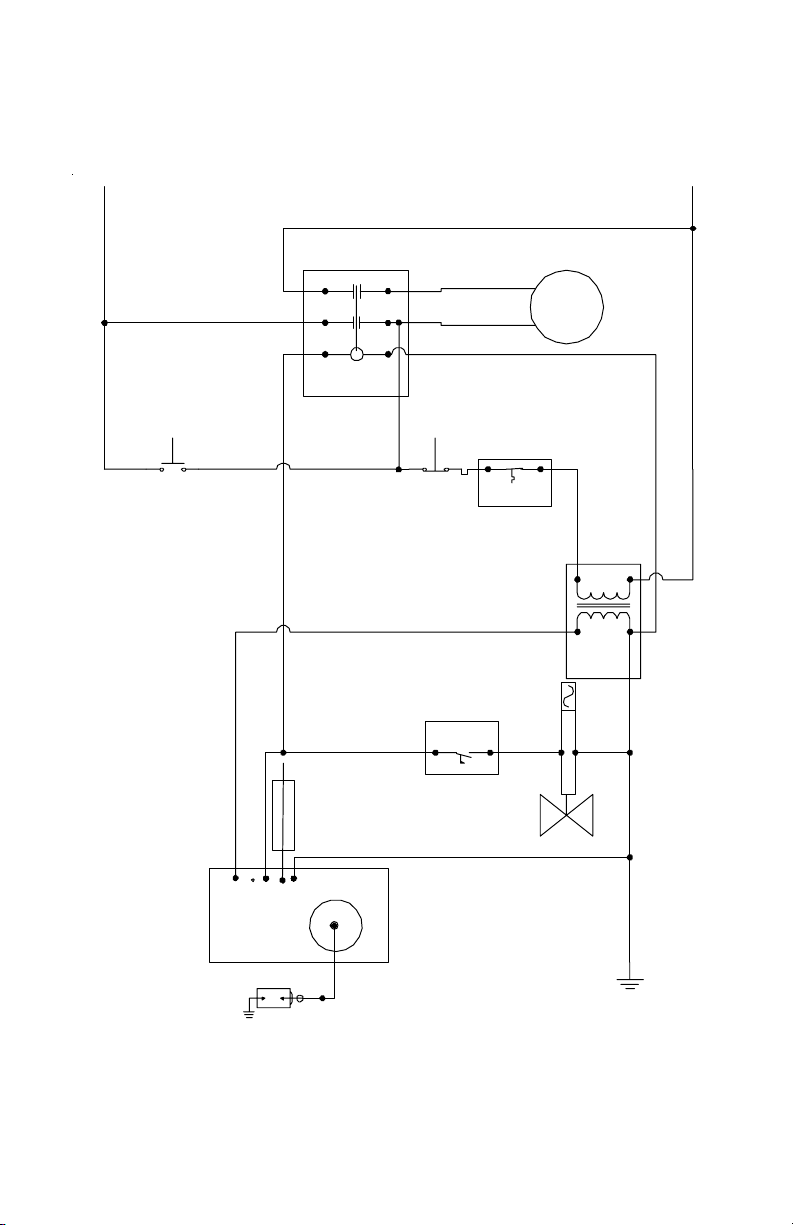
S100 CONNECTION WIRING
DIAGRAM
STOP
POWER
START
MOTOR
GAS
VALVE
BLU 15cm
GRN 7cm
TRANSFORMER
BLK 32cm
RELAY
POWER
BLK
GRN
WHT
T1
L1
A1
BLK 32cm
BLK 18cm
WHT 19cm
Motor Wire
Motor Wire
LINE
T2L2
A2
BLK 18cm
RED HT 64cm
RED HT 56cm
IGN 36cm
WHT 19cm
BLK 28cm
FLAME
ROD
CONTROL
IGNITION
2460D 601-002
FENWAL
G
S
V1
P
CONNECTOR
BLK 18cm
WHT 19cm
AIR SWITCH
BLK 30cm
LOAD
BLK 30cm
WHT 13cm
NC NO COM
BLK 28cm
SWITCH
HI LIMIT
NOTES: ALL WIRES 18GA. STR TEW 600V
UNLESS OTHERWISE SPECIFIED
NC
NO
COM
NO
COM
NC
CORD
TYPE STJW
14/3 61cm
24VAC
120VAC
BLK 20cm
WHT 20cm
18 Aug 2006
S100 Manual, Rev: 2.1.1 P/N: 634-6891 Page RM
S100 LADDER WIRING DIAGRAM
S1
FENWALL
#2460D-XXX-XXX
V1
NC
G
Power
SP
STARTBUTTON STOPBUTTON
M
AIRSWITCH
HILIMITSWITCH
POWER/MOTORRELAY
FLAME ROD
110V-24V
STEPDOW N
TR AN SF OR ME R
SOLENOIDVALVE
L
N
Table of contents
Other Haul-All Equipment Heater manuals

Popular Heater manuals by other brands


Pinnacle
Pinnacle MASTER MH-360A-TTC User's manual & operating instructions

Toyotomi
Toyotomi Radiant 101 Type A user guide

Chromalox
Chromalox NOR FOUND PD445 Installation and maintenance instructions

Scarlett
Scarlett SC-054 instruction manual

Holmes
Holmes HFH105 owner's guide

IRSAP
IRSAP THE RADIATOR COMPANY ISEO TRC-IS-O30 Fitting instructions