Awoco FM-1510SA1 User manual

USER’S GUIDE
Version: FM15-201902M
AIR CURTAINS
Super Power Models: FM-1509SA1, FM-1510SA1,
FM-1512SA1, FM-1515SA1, FM-1518SA1
STOP and Read! Test before installing
1. Do NOT plug in power cord to power source, use a screw driver to rotate
the fan wheels.
2. If the fan doesn’t rotate smoothly, remove the screws and open the front
cover.
3. Reseat the fan wheel bearings and align the motor to fix the issues.
Then replace the front cover back with tighten the screws.
4. Plug in 120V power source (some old air curtains might use 240V, verify
the power voltage if not sure); press the front switch to H or L to test it. If
the air curtain works normally, refer to section 3 through 7 to install the
air curtain. Refer to section 10 for technical support.
5. If the fan wheel is broken, contact Awoco (refer to section 10) to get the
fan wheel replacement.
6. After installation, if the air curtain doesn’t run, first step is to check the
magnetic switch. Refer to section 7 for troubleshooting.
PLEASE READ AND SAVE THESE INSTRUCTIONS.
Strongly recommend to test the unit before installation for any
defective or damage during shipment.

1
WARNING – TO REDUCE THE RISK OF FIRE, ELECTRIC SHOCK, OR INJURY
TO PERSONS, READ THE FOLLOWING CAREFULLY before attempting to
assemble, install, operate or maintain the product.
A. Always disconnect, lock and tag power source before installing or servicing product.
Failure to disconnect power source can result in fire, shock or serious injury.
B. Installation work and electrical wiring mu
st be done by qualified person(s) in
accordance with all applicable codes and standards, including fire-rated construction.
C. When cutting or drilling into wall or ceiling, do not damage electrical wiring and other
hidden utilities.
D. To reduce the risk of fire or electric shock, do not use this fan with any solid-state
speed control device
E. Repair and maintenance operations can only be performed by qualified personnel.
F.
Verify and ensure the rated voltage and frequency (please refer to the rating label) of
the air curtain is in compliance with the mains supply.
G.
Make sure the air curtain is securely mounted on the wall; otherwise, the air curtain
may fall and injury to persons.
CONTENTS
1. PRODUCT INTRODUCTIONS................................................................................................1
2. INSTALLATION PLANNING & CAUTIONS.............................................................................2
3. INSTALLATION INSTRUCTIONS............................................................................................3
4. TECHNICAL PARAMETER.....................................................................................................4
5. WIRING DIAGRAM.................................................................................................................5
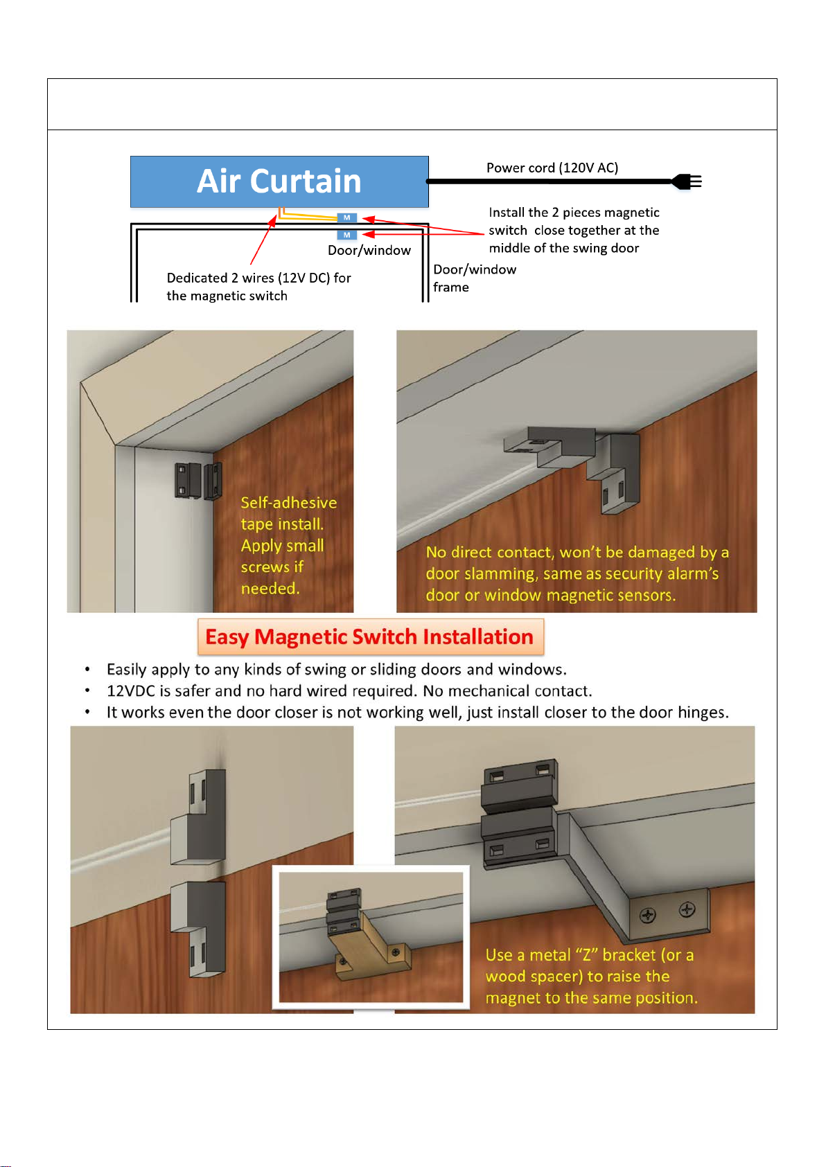
6. OPTIONAL MAGNETIC SWITCH INSTALLATION .................................................................5
7. TROUBLESHOOTINGS..........................................................................................................7
8. OPERATING INSTRUCTIONS................................................................................................7
9. MAINTENANCE AND CLEANING...........................................................................................8
10. SUPPORTAND CONTACT .................................................................................................8
1.PRODUCT INTRODUCTIONS
Air curtains are widely installed at the entrances of supermarket, theater, meeting room, hotel,
office room, storage room etc. They can reduce penetration of insects, outside dust,
unconditioned air into a conditioned space by forcing an air stream over the entire entrance to
create a comfortable environment for you.

2
2.INSTALLATION PLANNING & CAUTIONS
Must observe the following when installing air curtains:
Strongly recommend to test the unit before installation for any
defective or damage during shipment.
2.1 Please install the unit on a sturdy
supporting structure to avoid
shaking and
ensure its security (because the unit running
may cause the wall to become loose or
shake and make noise).
2.2 Please install the unit inside the room.
2.3 Install the unit between 7 feet to 8 feet
from the ground.
ATENCIÓN
:
Instalar la unidad entre los 7
a 8 pies desde del suelo.
2.4 When the entrance is wider than the
unit, it is recommended to install two or
more units in parallel. In this case, provide
20-40mm gaps between the units.
2.5 Don’t allow gaps between the unit and
the wall.
2.6 Don’t install the unit at a place where it
is splashed by water, exposed to excessive
steam, dust / explosive gas or corrosive
gas.
7’ – 8’

3
3.INSTALLATION INSTRUCTIONS
A. Installing on the concrete wall:
3.1.1 Unscrew the fixing screws to remove
the mounting plate from the back of the main
body.
3.1.2 Determine the mounting location with
the mounting plate. Drill holes and insert the
Zinc-Plated Steel Hex-Nut-Head Sleeve
Anchor (not included).
3.1.3 Tighten the nuts to secure the
mounting plate to the wall after cement
setting (use the washers and nuts as the Fig
shows).
3.1.4 Hang the main body onto the upper
end of the mounting plate, and then tighten
the bottom fixing screws back
to the
mounting plate.
B. Installing on the wooden wall: (Note: Make sure the screws are secured in the wood
studs, drill holes on mounting plate to align to the wood studs, and attach an extra
wood frame to the wall if needed.)
3.2.1 Refer to step 3.1.1 and determine the
mounting location, then mount
the mounting
plate to the wood studs securely
with tapping
screws.
3.2.2 Hang the main body onto the upper end
of the mountin
g plate, and then tie the bottom
fixing screws back to the mounting plate.

4
C. Installing from the ceiling: (Note: The ceiling brackets are not supplied.)
3.3.1 Remove the mounting plate from the main
body as per the step 3.1.1
3.3.2 Securely mount the ceiling brackets (not
included) as the Figure shows.
3.3.3 Set the mounting plate to the ceiling
brackets and tighten it securely as the Fig
shows. The position of the mounting plate can
be adjusted in vertical direction
according to
need, but the max distance is 100mm.
3.3.4 Hang the main body onto the upper end
of the mounting plate, and then tie the bottom
fixing screws back to the mounting plate.
Note: This air curtain should be installed indoor, should not have moisture, water, rain, or
snow reachable. Consult with your electrical professional for 120V electrical hard wiring.
WARNING: Make sure the air curtain is securely mounted on the wall; otherwise, the air
curtain may fall and injury to persons.
4.TECHNICAL PARAMETER
Model
No.
Max
entry
opening
(Inch)
Voltage
(V~Hz) Power
(W) Current
(A)
Max air
velocity
(FPM)
Air volume
(CFM)
Noise
level
(dB)
Net
weight
(Lb)
H L H L
FM-1509SA1
38
120V,
60Hz
300
3.13
2559 (H),
1968 (L)
1177
942
58
56
33.1
FM-1510SA1
42
350
3.65
1354
1059
58
56
37.5
FM-1512SA1
50
350 3.65 1648 1295 59 57 43.0
FM-1515SA1
62
400 4.17 2119 1648 60 58 48.5
FM-1518SA1 74 600 6.25 2354 1884 61 59 61.7
Note: ETL certified models have 1 speed only, which is the High speed. The data are
subjected to change without notice due to product development.

5
5.WIRING DIAGRAM
6.OPTIONAL MAGNETIC SWITCH INSTALLATION
This air curtain comes with a magnetic door switch, contact seller or Awoco if you are missing a
magnetic switch. The dedicated 2 wires (Yellow) are to connect to the magnetic switch.
Note: Keep the 2 wires connected (closed) if the magnetic switch is not used.
Connect the magnetic door switch:
Cut the nut off the 2 yellow wires, and connect the 2 yellow wires to the magnetic switch one by one. Use the
black electrical tape to seal the connection.

6
Mount the 2 pieces magnetic switch to the door/window edge and frame; keep them close when the
door/window is closed. If needed, apply a metal “Z” bracket to raise the magnet to the same position. Note: Do
NOT use big screws!!! Oversized screws will damage the magnetic switch internally.

7
7.TROUBLESHOOTINGS
Failure symptom
Possible causes
Troubleshoot and solution
Fan wheel is broken
Damaged during
shipment
If the fan wheel is broken and your purchase is from
an authorized seller, contact Awoco to get a fan wheel
replacement. Changing a fan wheel is not difficult.
Fan wheel is stuck
or generates
strange noise
The fan wheel is
not seated
properly
Please follow the instruction to open the front cover.
Check if the fan wheels are touching something.And
open the side panel to reseat the fan wheels to the
correct positions.
The air curtain
doesn’t turn on.
(Make sure your
power outlet is
120V before
plugging in. Some
old air curtains
might use 240V)
The magnetic
switch is defective
or loosen
connection
Remove the magnetic switch connection, directly
connect the 2 yellow wires together then test the air
curtain. 80% of the failure is due to the magnetic
switch setup. Don’t use oversize screws, and make
sure the connection is secure.
Check if the front
switch is function
After a long period of time, the L/Off/H (or On/Off)
switch might be burnt out. Please test the switch.
Circuit board
failure or no power
to circuit board
Toggle the magnetic switch and the front switch; hear
if “Tic-Tac” sounds from the relay on the circuit board.
No sound means no power to motor from circuit
board. Please check if the power gets into the
IN_L(Hot) and IN_N(Neutral) pins.
Motor doesn’t run.
But if push the fan
wheel, motor slowly
rotates or rotates
reversely
Startup capacitor is
not connected
securely or
defective
Check if the 2 yellow/orange wires securely connect
to the capacitor under the motor. Remove the fan
wheels and motor to get access if needed.
After above
troubleshoot
processes, motor
still doesn’t turn on
Motor is defective
This chance is very low but it might happen.
Use Ohm meter to measure the continuity between
motor’s white wire and the blue wire to check if it is
open. Open means defective.
Feel free to contactAwoco technical support at 1-888-412-3428 if you need help.
Awoco has all the parts for 1 year limited warranty, including fan wheels, magnetic switches,
circuit boards, motors, etc.
8.OPERATING INSTRUCTIONS
8.1 Connect power (120V 60Hz) to the unit.
8.2 Press the switch to the left or right to turn on the unit. [L] - Low speed, [H] - High speed.
8.3 Adjust the air deflector to slightly outward at about 10 to 15 degrees to obtain optimum effect.

8
9.MAINTENANCE AND CLEANING
WARNING:
A. Any service is to be performed only by qualified personnel who are familiar with local
codes and regulations and are experienced with this type of product.
B. Always unplug or disconnect the appliance from the power supply before servicing or
cleaning the unit.
C. Never use petrol, benzene, thinners or any other such chemicals for cleaning the unit.
D. Don’t allow water or any liquid to enter the motor.
9.1 Use the unit at the rated voltage and frequency indicated on the rating label.
9.2 Disconnect power source before unit installation or maintenance service.
9.3 Routine maintenance must be done every year.
9.4 Plastic parts should be cleaned with mild soap water, thoroughly remove soap film with a
clean damp cloth.
9.5 Wipe the exterior surfaces of the fan with a moistened cloth with a solution of mild detergent
and water.
9.6 Dry the case with a soft dry cloth before operating the unit.
10.SUPPORTAND CONTACT
Contact your local seller for exchange or repair.
Visit www.awoco.com for most updated information.
Email to sales@awoco.com or call 1-888-412-3428 for technical support and sales activity.
This manual suits for next models
4
Table of contents
Other Awoco Heater manuals