HAULOTTE GROUP 1 SAFETY
5
LIST OF ILLUSTRATIONS
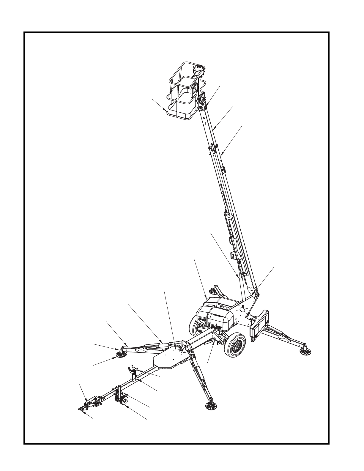
Figure 2-1. Range of Motion............................................................................................................... 15
Figure 3-1. Ground Control Panel ...................................................................................................... 22
Figure 3-2. Platform Control Panel..................................................................................................... 24
Figure 3-3. Boom Travel Latch........................................................................................................... 26
Figure 3-4. Platform Travel Latch....................................................................................................... 27
Figure 3-5. Platform Locking Pins ...................................................................................................... 27
Figure 3-6. Outrigger Controls............................................................................................................ 28
Figure 3-7. Hand Pump Controls for Manual Operation..................................................................... 30
Figure 3-8. Manual Boom Lowering Valve .........................................................................................31
Figure 3-9. Trailer Hitching................................................................................................................. 33
Figure 3-10. Lift Instruction.................................................................................................................. 34
Figure 3-11.Transport Instruction ........................................................................................................ 35
Figure 4-1. Battery Charger Faceplate............................................................................................... 38
Figure 4-2. Outrigger Position Switch................................................................................................. 41
Figure 4-3. Hydraulic Reservoir.......................................................................................................... 42
Figure 4-4. Wheel Nut Tightening Sequence ..................................................................................... 44
Figure 4-5. Display Run Time Hours ................................................................................................. 45
Figure 4-6. Machine Position for Slew Ring Measurement ............................................................... 46
Figure 4-7. Slew Ring Position Measurement ................................................................................... 46
Figure 4-8. Platform Position after Rotation ...................................................................................... 46
Figure 4-9. Position Machine for Leveling .......................................................................................... 48
Figure 4-10. Level Sensor Digitally Based .......................................................................................... 48
Figure 4-11. Level Sensor Pendulum Based....................................................................................... 48
Figure 4-12. Ground (Lower) Control Panel for Leveling System....................................................... 49
Figure 4-13. Platform Position............................................................................................................ 50
Figure 4-14. Ground (Lower) Control Panel for Overload Protection ................................................. 50
Figure 4-15. Manual Outrigger Control Wire Harness........................................................................ 54
Figure 4-16. Bottom Side of the Ground (lower) Control Box.............................................................. 54
Figure 4-17. Hydraulic Power Unit ..................................................................................................... 54
Figure 4-18. Attaching the Pressure Gauge to the Hydraulic Power Unit. ......................................... 55
Figure 4-19. Motor Controller ............................................................................................................. 68
Figure 5-1. Location of Master Cylinder ............................................................................................. 71
Figure 5-2. Location of Slave Cylinder ............................................................................................... 72
Figure 5-3. Location of Manual Lowering Valves for Lift Cylinder Replacement................................ 73
Figure 5-4. Push “Button” Lowering Valve ......................................................................................... 73
Figure 5-5. Lift Cylinder Replacement................................................................................................ 73
Figure 5-6. Outrigger Cylinder Replacement...................................................................................... 75
Figure 5-7. Cylinder Valve Removal................................................................................................... 75
Figure 7-1. Drive and Set Controls..................................................................................................... 92
Figure 7-2. Load Sense Module ......................................................................................................... 95
Figure 7-3. Ground Control Panel Receptacle ................................................................................... 95
Figure 7-4. Platform Removal ............................................................................................................ 96
Figure 7-5. Material Lift Hook Installation........................................................................................... 96
Figure 7-6. Material Lift Stow Position................................................................................................ 97
Figure 7-7. Material Lift “In Use” Position........................................................................................... 97
Figure 7-8. Manual Platform Rotator .................................................................................................. 98
Figure 9-1. Standard Brake Adjustment Procedure ......................................................................... 134
Figure 9-2. Drive & Set Brake Adjustment Procedure ...................................................................... 136