Hausmann 1396 Operation manual

HAUSMANN INDUSTRIES, INC.
130 UNION STREET, NORTHVALE, NJ 07647
↥2004 Hausmann Industries, Inc.
Model 1396 (Less dowel holes and apparatus)
Model 1398 (With dowel holes and apparatus)
Ph: (201) 767-0255 Fax: (201) 767-1369
Models 1396 and 1398 Operation and Service Guide
11/3/04

Models 1396, 1398 Power Height Parallel Bars
Operation and Service Guide
CONSTRUCTION
The drive system consists of (4) "TMA" synchronized lifting columns which can be elevated and
lowered by means of control box and associated control switch with LED height readout (in
inches).
The TMA are electrical linear drives in no-clearance aluminum guide tubes. Surfaces of vertical
lift columns are anodized aluminum. A 24 V-DC motor drives through a worm drive and
threaded rod. A tapped nut, which is firmly attached to the push drive, moves up and down the
threaded rod and this provides the forward movement. Extension and contraction of the
telescopic tubes is by means of changing the direction of the rotation of the motor.
LIFTING COLUMNS
TABLE OF CONTENTS
ᔣConstruction
ᔣLifting Columns
ᔣControl Box
ᔣHand Switch
ᔣOperating Method
ᔣTechnical Data
ᔣPatient Weight Capacity
ᔣOperation
ᔣMemorizing the Memory Positions
ᔣPositioning to Memorized Position
ᔣMaintenance and Care
ᔣWiring Diagram
ᔣModel 1396 and 1398
ᔣDetail of Steel Wiring Chase
ᔣDetail of Hand Control Switch
ᔣDetail of Cord Connections
ᔣDetail of Control Box
ᔣDetail of Width Adjustment Knob
ᔣModel 1398 Only
Page 1
Page 1
Page 1
Page 2
Page 2
Page 2
Page 2
Page 3
Page 3
Page 4
Page 4
Page 5
Page 6
Page 6
Page 7
Page 7
Page 8
Page 9
Page 10
.....................................................................................................................
.................................................................................................................
......................................................................................................................
.......................................................................................................................
.............................................................................................................
..................................................................................................................
...................................................................................................
.........................................................................................................................
...................................................................................
...................................................................................
.....................................................................................................
................................................................................................................
......................................................................................................
.......................................................................................... .
........................................................................................ .
..............................................................................................
........................................................................................................
......................................................................................
............................................................................................................ .
1
↥2004 Hausmann Industries, Inc.
11/3/04
The control and supply of the lifting columns is by means of an associated micro-processor
control unit IE.
(4) Column system control unit ... LD-014 Control box is double insulated for safety.
CONTROL BOX

HAND SWITCH
Operation of the system is by means of an LD-011 Hand Control Switch (mounted on black
wooden support post near one end of platform).
PATIENT WEIGHT CAPACITY
400 lbs.
NOTE: Handrail motors are designed to electrically adjust in height , and to be stable under use
when at their fixed height level. Motors are not designed to "lift" full weight of patient from
sitting to standing position.
Not designed for continuous use.
Intermittent 10%; 30 seconds ON
270 seconds OFF
Thermal overload: Unit will shut down automatically if motor overheats due to continuous use.
Unit will restart automatically after "cool off" peiod of up to 15 minutes.
OPERATING METHOD
2
↥2004 Hausmann Industries, Inc.
11/03/04
Push Force (1 Lift Column)
Stroke
Speed
110V, 60Hz, 2.5 Amps
All electrical components are U.L. recognized components, furniture grade.
There is sufficient wheelchair clearance for most 16" and 18" wide seat wheelchairs, but
insufficient clearance for 20" or wider seat wheelchairs.
TECHNICAL DATA
1000 N
15" (29" to 44" high)
2.1"/second
3
↥2004 Hausmann Industries, Inc.
11/3/04
MEMORIZING THE MEMORY POSITIONS
As the height adjustment is variable and random from patient to patient, we normally do not
recommend use of memory control, but it is an option if needed.
With the memory capacity, you can specify a given handrail height. Up to four different heights
can be memorized. These memorized positions can be later re-specified.
Press . An S appears in the LED display.
Press one of the position keys , , or .
After the position key has been pressed, the number of the position key appears in the LED
display next to S. After the memorization procedure, a double-click is heard, and after
approximately 2 seconds the current height appears again in the LED display.
1
S
32 4
OPERATION (See hand control switch at top of page 7.)
Unit is pre-wired and pre-tested at factory ready for use. Set the platform in place and plug
power cord into 110V wall outlet.
IMPORTANT
Follow these instructions exactly upon initial use, as follows:
Press "Up" Button and elevate both handrails approximately 2" (not more) - the LED
display will read-out the height in inches.
Press "Down" Button and lower both handrails until they are at lowest height
(bottomed out). The unit will stop automatically at lowest level.
Press "Down" Button again for 5 seconds to make sure all (4) columns have
bottomed out to their lowest height.
Press "Up" Button and elevate hand rails to maximum highest height of 44".
Press "Up" Button again for a second or two to make sure all (4) lift motors are at
maximum height.
Press "Down" Button to lower to normal height level.
YOU ARE NOW READY TO OPERATE FOR NORMAL USE.

MAINTENANCE AND CARE
Maintenance
The motor cables and power cord should be periodically checked for any signs of wear or tear.
Care
A damp (non-dripping) cloth is best for manual cleaning.
Responsibility
Responsibility for the operation of the apparatus falls in all cases on the proprietor or operator, if
the apparatus has been improperly installed , maintained or adjusted, or if use is made of it
which does not correspond with its intended use.
4
↥2004 Hausmann Industries, Inc.
11/3/04
POSITIONING TO MEMORIZED POSITIONS
Variant A
Press and hold one of the position keys , ,
or .
The handrails move to the selected position as long as the key is
kept pressed. If the key is released, the handrails stop.
If the key is kept pressed, the handrails keep moving until they
reach the memorized position.
Variant B (optional)
Double-click one of the position keys , ,
or .
The handrails automatically move to the memorized position.
1 32
4
1 32
4
If a key is pressed during automat-
ic positioning the handrails stop
moving.
i

1396/1398 WIRING DIAGRAM
5
↥2004 Hausmann Industries, Inc.
11/3/04
HS
2134
56789
Lift Motor
Column 4
# TMA
Lift Motor
Column 3
# TMA
Lift Motor
Column 2
# TMA
Lift Motor
Column 1
# TMA
Control Box
# LD-014
Blank
Electrical Power Cord
hardwired to Control Box
110V, 60 Hz
Port
Actuator Connecting Cable
(at both ends of cable)
Memory
Buttons
LED
Display Up Down
Hand Switch Panel
# LD-011
Unit is shipped fully wired and ready for operation.
1
S
234
Connectors
Port Port Port Port
Note:
TMA Lift Motors
are 24V-DC.
CAUTION: You must remove 110V power plug before attempting any factory authorized repair.
ALL CORD CONNECTIONS FROM LIFT COLUMNS TO CONTROL BOX ARE PRE-CONNECTED AT
FACTORY. DO NOT REMOVE CONNECTIONS WITHOUT FACTORY AUTHORIZATION.
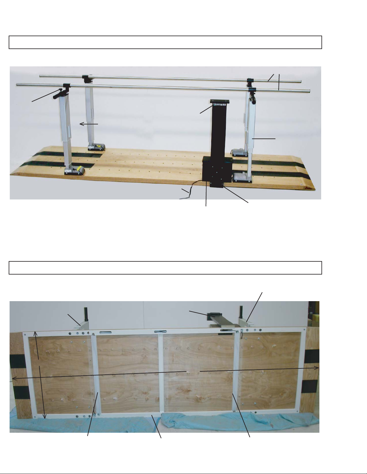
MODEL 1396 AND 1398 (1396 has no dowel holes in platform)
DETAIL OF STEEL WIRING FRAME (UNDER WOOD PLATFORM)
6
↥2004 Hausmann Industries, Inc.
11/3/04
Manual
Width
Controls
110V Power Cord
10' Stainless
Steel Handrails
(4) "TMA"
Powerlift
Columns
Control Panel
with LED display
of height of bars
(in inches)
Black upright
with hand switch
"height" control
Control Box
enclosure
Lift
Column
Black upright
with switch control
Steel wiring chase
underneath wood platform
Lift
Column
27" Clearance
between uprights
Removable plastic cover
plate to access wires
Removable plastic cover
plate to access wires
130"
38"

1
S
234
DETAIL OF HAND CONTROL SWITCH WITH LED DISPLAY OF HEIGHT READ-OUT
ALL CORD CONNECTIONS FROM LIFT COLUMNS TO CONTROL BOX ARE PRE-CONNECTED AT
FACTORY. DO NOT REMOVE CONNECTIONS WITHOUT FACTORY AUTHORIZATION.
7
↥2004 Hausmann Industries, Inc.
11/3/04
Memory Controls Height
read-out
in inches
"Up"
Button
"Down"
Button
10'
Stainless
Steel
Handrails
Width
Control
Knob
TMA Lift Column
Cord Connection
to Control Box
(See wiring diagram
on page 5)
Wood Platform
(Shown with #1398
dowel holes - #1396
has no dowel holes)
TMA Lift Column
Cord Connection
to Control Box
(See wiring diagram
on page 5)
See page 2 for initial operating instructions upon delivery.
Mounting
Plate
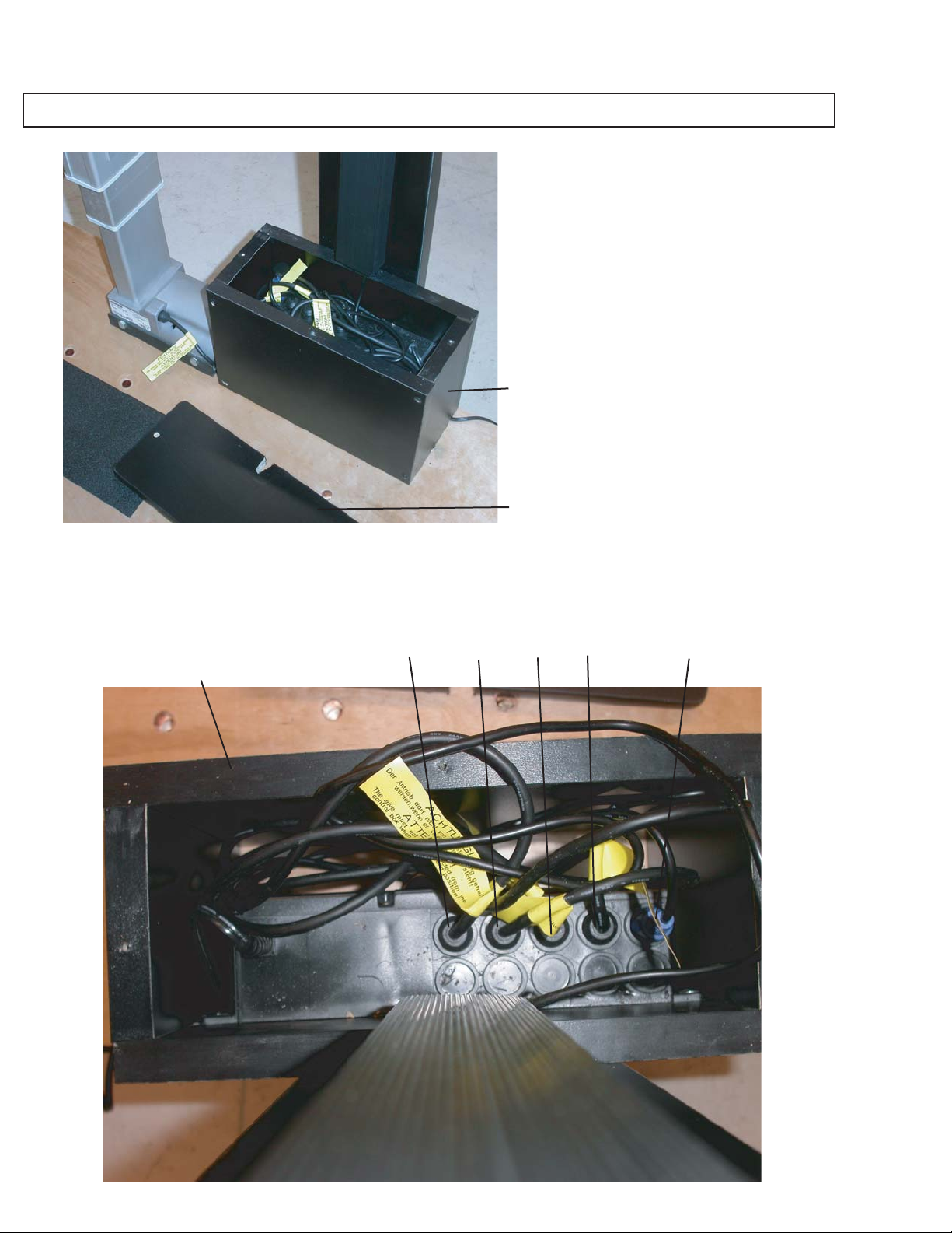
DETAIL OF CONTROL BOX WITH LID "OFF"
8
↥2004 Hausmann Industries, Inc.
11/3/04
Control Box
Lid Removed
LD-014
Control Box
(shown with lid "off")
Port 4 Port 1Port 2Port 3 Control Switch Port
CAUTION:
Do not open or access control box
without prior factory authorization.
Disconnect 110V power cord before
authorized access.
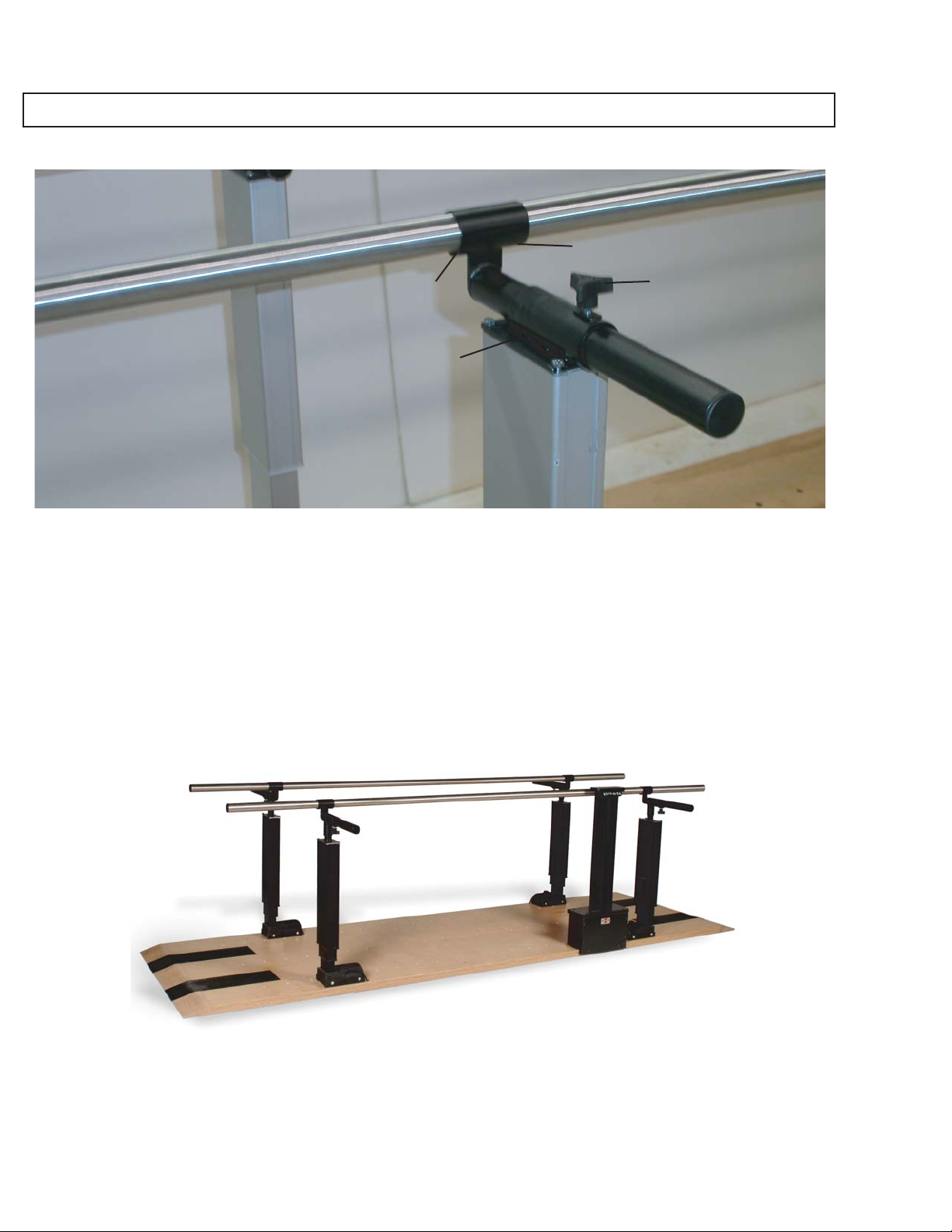
DETAIL OF WIDTH ADJUSTMENT KNOB OF STAINLESS STEEL HANDRAIL
9
↥2004 Hausmann Industries, Inc.
11/3/04
Width Control Knob
Mounting plate for
width control knob
To adjust width, turn both width control knobs counter-clockwise until "loose", then move handrail "in" or
"out" as needed, and retighten friction control knobs to lock-in width position of handrails. Width adjusts
from 15" to 28" wide. Each side should be adjusted at the same time. See image below: Adjust side A-B,
then adjust side B-C.
1/4" x 1/20
Set Screw
1/4" x 1/20
Set Screw
AB
CD

1398 ONLY
10
↥2004 Hausmann Industries, Inc.
11/3/04
Detail showing (23) rows of holes in wood platform for variable placement of "blue" ladder steps
Detail showing insertion of ladder step into dowel holes in wood platform.
Detail of (1) balance beam 6' 5" long x 6" wide x 3" high.
Detail of dowel pin of balance beam.
Control Box
Wood Enclosure
4 1/2"
typical
Control box with lid in place
(Do not remove lid without
factory authorization.)
(11) Ladder Steps
included in #1398
Position dowel pins on each end of
balance beam in center row of dowel
holes before use.
This manual suits for next models
1
Table of contents
Other Hausmann Medical Equipment manuals


Popular Medical Equipment manuals by other brands


Agilent Technologies
Agilent Technologies Varian VK 7025 Operator's manual

FujiFilm
FujiFilm Sonosite PX System Service manual

Atos Medical
Atos Medical PROVOX Vega Instructions for use

Welch Allyn
Welch Allyn Acuity Directions for use

DEHAG
DEHAG Nystagmus Spectacle User instruction

HeartCare
HeartCare LOX100A user manual


