Hausmann 6058 Installation instructions

rev. 122817MH
©2017 HAUSMANN INDUSTRIES, INC.
HAUSMANN INDUSTRIES, INC.
Installation/Operation Instructions
Model 6058 - Wheelchair Accessible Hi-Lo Tilt Table
NOTE: Table must be elevated
to maximum height of 33”
before you can operate tilting
function of 0° to 90°.
Model 6058
Specifications
•Unique wheelchair accessible design is ideal for rehabilitation or nursing homeuse.
•Electric operated actuators provide quick and smooth control of the Tilt and Heightadjustments.
•The comfortable 76” x 26” cushioned top is available in Gray vinyl.
•Equipped with (3) safety straps with “hook and loop” closures.
•Electric Hi-Lo lift mechanism adjusts from 19” low wheelchair height to 33” high.
•Tilts from horizontal to 90°. Unit should be raised to max height before tilting.
•Tilt angle indicator on both sides of table.
•Pivoting Footboard with rubber tread.Angle of the Footboard tilt is adjustable with spring loaded
controls on both sides.
•Hands-free foot control.
•Includes unique Emergency Tilt Release Handle that manually lowers tilted table back tohorizontal.
•(4) 3” dia. swiveling locking casters.
•Heavy-duty steel frame is cream powder coated epoxy finish.
•110V, 60Hz. 3.15 Amps. Hospital grade plug.
•Speed of Tilt: 3° per second (with average weight load)
•76”L x 26”W x 19” - 33”H

rev. 122817MH
©2017 HAUSMANN INDUSTRIES, INC.
Introduction
Congratulations on the purchase of one of the Hausmann range of tilt tables. We are confident it will provide many
years of excellent performance.
This manual presents all the relevant operator information for your Hausmann Tilt Table.
All Hausmann Tilt Tables are designed to provide a comprehensive range of features and offer exceptional value
for money. The design principles employed ensure that the product is extremely robust, long-lasting and provides
a safe and ergonomically sound environment in which the practitioner can treat his or her patients. The table you
have purchased is the result of many years of research into the needs of the practitioner and the development of
the most effective way of satisfying those needs in a treatment table.
The best quality materials are utilized in the construction of the table and the latest industry-proven fabrication
methods are used.
NOTE: FOR OPERATIONAL SAFETY, THE HEIGHT FUNCTION AND TILT FUNCTION ARE INDEPENDENT
OF EACH OTHER. TABLE HEIGHT ELEVATION FUNCTION SHUTS OFF AUTOMATICALLY WHEN YOU
OPERATE TILT FUNCTION AND TABLE TILT FUNCTION SHUTS OFF AUTOMATICALLY WHEN YOU
OPERATE HEIGHT FUNCTION.
FOR PROFESSIONAL THERAPY USE ONLY.
NEVER LEAVE PATIENT UNATTENDED WHILE ON TABLE.
PLUG POWER CORD INTO 3 POLE WALL RECEPTACLE PREFERABLY HOSPITAL GRADE THAT IS
CORRECTLY WIRED TO BUILDING POWER SYSTEM. PERIODICALLY CHECK GROUNDING CONTINUITY
AND CHECK FOR FRAYED WIRES OR WORN INSULATION ON POWER CORD.
REMOVE UNIT POWER PLUG FROM WALL OUTLET IN CASE OF EMERGENCY OR DURING ROUTINE
CLEANING OR SERVICE.
ANY SERVICE MUST BE PERFORMED BY AUTHORIZED QUALIFIED TECHNICIANS.
ELECTRICAL SYSTEM IS NOT DESIGNED FOR CONTINUOUS USE. AS A SAFETY FEATURE, UNIT
WILL SHUT DOWN IF OVERHEATING OCCURS AND WILL GO BACK ON AFTER COOLING OFF
PERIOD.

rev. 122817MH
©2017 HAUSMANN INDUSTRIES, INC.
Warranty Statement
Hausmann Industries, Inc. will warrant parts for this table against defects in manufacture for a period of three
years from the date of purchase.
Upholstery, cables are excluded from this warranty.
Providing
The table has not been serviced by person not authorized by Hausmann Industries, Inc. and has not been
misused or tampered with and has been used on the correct voltage as branded on it.
This Warranty Excludes:
Parts of this table the failure of which, in the opinion of the dealer or manufacturer, is a result of misuse or
abuse or any other reason not directly attributed to a fault in manufacture.
In the Event of Failure:
If authorized by your Hausmann dealer or Hausmann Industries, Inc., the complete table should be returned to
the dealer from which it was purchased or to the nearest authorized service agent, together with a full report,
freight paid and insured.
Under No Circumstances
Shall Hausmann Industries, Inc. or their agents or dealers be liable in any manner whatsoever for any
compensation or damages to any person occasioned by this table for any loss, injury or any damage
occasioned by or as a result of misuse or abuse of this table. Hausmann Industries, Inc. or their agents or
dealers shall not be liable for any losses, financial or otherwise, suffered as a consequence of any failure of the
table which is rectified under the terms of this warranty agreement.
Loss in Transit:
The warrantor does not accept any responsibility for loss or damage to the table in transit.
Any express or applied conditions, statements of warranty, statutory or otherwise (save specifically provided
above) is hereby excluded.
Acceptance of this agreement
Is indicated by the purchaser taking possession of this table and putting it to use.
3
rev. 122817MH
©2017 HAUSMANN INDUSTRIES, INC.
Fig. 1
Fig. 2
Fig. 3
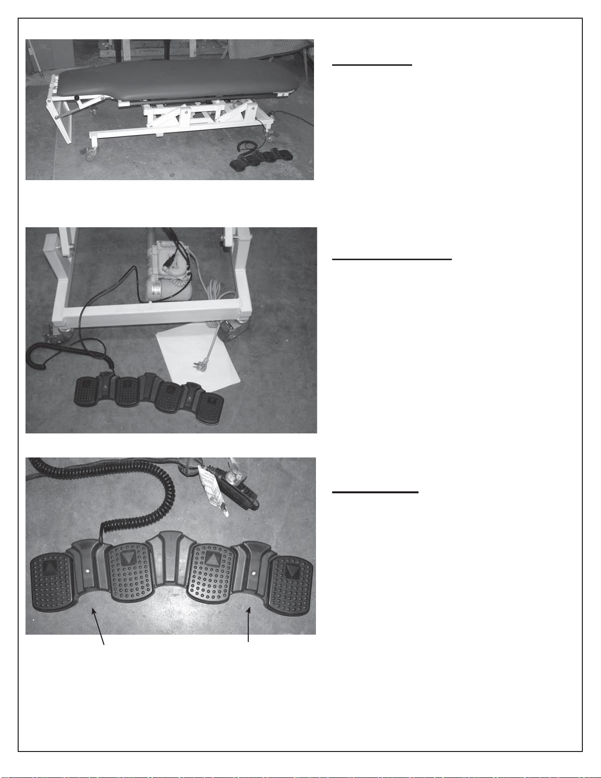
OPEN CARTON
Tilt Table is shipped in lowest (19”) horizontal
position and foot plate is shipped in most ex-
treme “out of the way” position as shown.
POWER CORD & PLUG
110V Power cord comes out from Control Box
at bottom rear of frame. Plug power cord into 3
pole wall receptacle preferably hospital grade
that is correctly wired to building power system.
Periodically check grounding continuity and
check for frayed wires or worn insulation on
power cord.
FOOT CONTROL
Unit has low voltage electrical foot switch. Con-
trolsfor Up▲andDown▼of horizontaleleva-
tion are on left facing andcontrols for Up▲and
Down ▼of tilt are on right facing.
Horizontal Elevation Tilt Up/Down
4
rev. 122817MH
©2017 HAUSMANN INDUSTRIES, INC.
Fig. 4
Fig. 5
Fig. 6
5
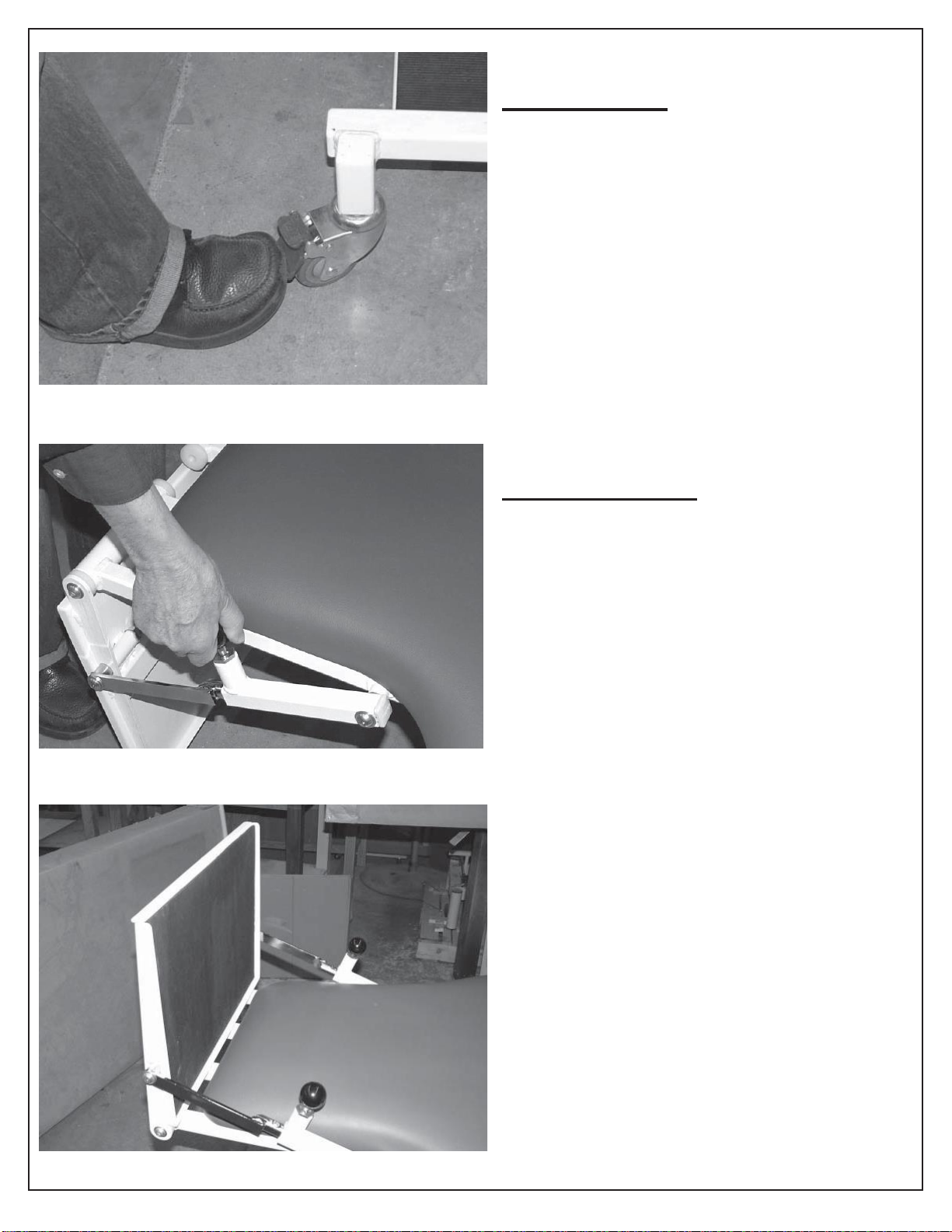
LOCKING CASTERS
You must lock brakes of all (4) casters by depress-
ing brake pedal down before patient use.
PIVOTING FOOT PLATE
You must adjust angle position before patient use.
There are two black spring loaded control handles.
Lift up and turn knobs to “open”. Adjust foot plate
into an approximate 90° right angle position (there
are adjustment holes on steel rod). Turn both knobs
to re-lock the foot plate into desired position as
shown. Turn both knobs to snap lock the ft plate into
desired pos as shown in fig 6 below.
NOTE: DO NOT OPERATE TILT IF FOOT PLATE
IS IN “OUT OF WAY” POSITION AS SHOWN IN
FIG 5.
Foot plate shown in 90° operational position.

rev. 122817MH
©2017 HAUSMANN INDUSTRIES, INC.
Fig. 7
Fig. 8
6
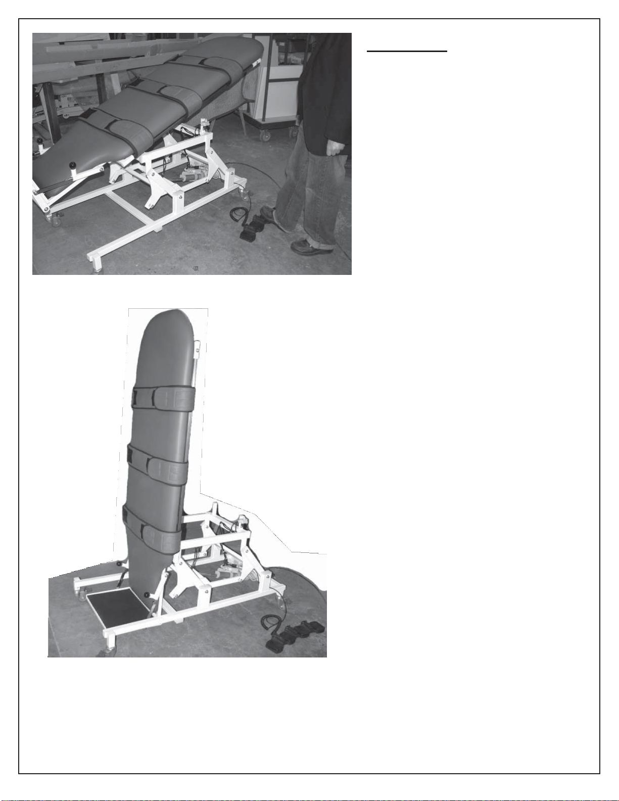
VELCRO STRAPS
Attach (3) Velcro patient straps to strap
patient securely on table before use. There
are long stainless steel bars on both sides
of table that retain straps. Make sure straps
are securely velcro-locked before use.
ELEVATE TABLE HEIGHT
Depress horizontal height foot control and
elevate table to its highest (approx. 33”)
horizontal position
NOTE: TABLE MUST BE ELEVATED TO
HIGHEST HEIGHT BEFORE YOU CAN
ACTIVATE TILT MECHANISM.
NOTE: For operational safety, the height
function and tilt function are independent of
each other. Table height elevation function
shuts off automatically when you operate
tilt function and table tilt function shuts off
automatically when you operate height
function.
rev. 122817MH
©2017 HAUSMANN INDUSTRIES, INC.
Fig. 9
OPERATE TILT
With table at its maximum height, you
are able to activate tilt mechanism by
depressing Up ▲ Tilt pedal of foot control.
Table is now at maximum 90° tilt or any
angle tilt angle from 0° to 90° that you
select.
NOTE: WITH TABLE AT MAXIMUM 33”
HEIGHT, USE FOOT CONTROL TO
LOWER THE TILT TOP DOWN TO FLAT
HORIZONTAL. TILT TOP MUST BE AT
FLAT HORIZONTAL BEFORE YOU CAN
LOWER TABLE HEIGHT.
7
Fig. 10

rev. 122817MH
©2017 HAUSMANN INDUSTRIES, INC.
Fig. 11
TILT INDICATOR
Note that there are Tilt Angle
Indicators on both sides of underside
of the top beneath head section.
Fig. 12
EMERGENCY MANUAL RELEASE
HANDLE
In case of power outage, or patient
emergency, to lower tilt top from
90° to 0°, pull large red Emergency
Handle “down” and you can manually
lower tilted top down to flat horizontal
position. You must use two hands as
shown to lower (or raise) top.
NOTE: WHENEVER YOU ACTIVATE EMERGENCY RELEASE HANDLE TO LOWER TOP , YOU MUST
MANUALLY USE RED HANDLE TO RAISE THE LOWERED TOP BACK TO THE TILT ANGLE IT WAS IN
BEFORE YOU LOWERED IT.
( FOR EXAMPLE... IF THE TOP WAS AT90° WHEN THE EMERGENCY OCCURRED, YOU MUST
MANUALLY USE RED RELEASE HANDLE TO RETURN THE TOP BACK TO ORIGINAL 90° TILT POSITION,
BEFORE YOU ACTIVATE THE ELECTRICAL FOOT CONTROL.)
THE MANUAL RETURN OF TOP TO IT’S ORIGINAL POSITION IS REQUIRED BEFORE YOU COMMENCE
USING THE ELECTRIC FOOT CONTROL TILT FUNCTION.
8
Fig.5

rev. 122817MH
©2017 HAUSMANN INDUSTRIES, INC.
Fig. 13
Fig. 14
Fig. 15
DETAIL OF TILT MOTOR AND MOUNTING
LOCATED NEAR HEAD OF UNDERSIDE OF TOP.
Motor is Dewarts model Megamat MC4 6000N
DETAIL OF HEIGHT ELEVATION MOTOR AND
UNIT CONTROL BOX LOCATED AT BOTTOM
REAR OR TABLE CHASSIS.
Motor Is Dewarts Model Megamat MC4 6000N
Control Box Is Dewarts Model MCL 120 V, 60 HZ,
3.15 AMPS
Intermittant Operation 2 min/18 min
DETAIL OF CONTROL BOX AND PORT
CONNECTIONS
Power Cord
Port 1 - Foot Control Port 2 - Height Motor Port 3 - Tilt Motor
9

rev. 122817MH
©2017 HAUSMANN INDUSTRIES, INC.
Fig. 16
Fig. 17
Fig. 18
10
MICRO-SWITCH HARNESS
DETAIL OF LOWER “HEIGHT” MICRO SWITCH
ASSEMBLY (CLOSED).
When you raise horizontal height to max 33”H, you
enable the vertical tilt function. Once you activate
tilt you disable height function.
DETAIL OF UPPER “TILT” MICRO SWITCH
ASSEMBLY (OPEN).
When microswitch on the tilt is “open”, it disables
the horizontal height function, and you are able to
operate the vertical tilt.
DETAIL OF UPPER “TILT” MICRO SWITCH
ASSEMBLY (CLOSED).
When microswitch is “closed” you are able to
operate the horizontal height function and it
disables the vertical tilt function.
Table of contents
Other Hausmann Medical Equipment manuals


