Haussmann Xpert PT2502RN User manual
– 1 –
Operator’s Manual
10 IN. (254 MM) TABLE SAW
Model No.: PT2502RN
RONA Code: 89335000
QUESTIONS? 1-866-206-0888
Our Customer service staff is available to help you.
For help with product assembly, to report damaged or missing parts, or for any other
information, please call our toll-free number: 1-866-206-0888.
Register your product
We invite you to register your product online to make future communications easier.
To do so, simply visit our website www.haussmanntools.com.
SAVE THIS MANUAL
You will need this manual for safety instructions, operating procedures, and warranty.
Put it and the original sales invoice in a safe, dry place for future reference.

– 2 –
TABLE OF CONTENTS
PRODUCT SPECIFICATIONS
WARNING
!
To avoid electrical hazards, fire hazards or damage to the tool, use proper circuit protection. Use a seperate electrical
circuit for your tools. To avoid electrical hazards, fire hazards or damage to the table saw, use proper circuit protection.
This table saw is wired at the factory for 110-120/220-240 Volt operation. It must be connected to a 110-120 Volt / 15
Ampere or 220-240 Volt / 7.5 Ampere time delay fuse or circuit breaker. To avoid shock or fire, replace power cord
immediately if it is worn, cut or damaged in any way.
2011/03
MOTOR SAW
Type Induction Table Size 27-1/8 in. x 20-1/8 in.
(688 mm x 512 mm)
Amps 15 / 7.5 Table Extensions Right & Left
Voltage 120 / 240 Extension Fence Capacity 24 in. (610 mm) Right
Hz 60 Blade Size 10 in. (254 mm)
RPM (no load) 3450 Blade Arbour 5/8 in. (15.9 mm)
Overload Protection YES CUTTING CAPACITY
MITRE GAUGE YES Maximum Cut Depth @ 90o3-1/2 in.(88.9 mm)
RIP FENCE YES Maximum Cut Depth @ 45o2-1/4 in.(57.1 mm)
Maximum Dado Cut Width 13/16 in.(20.6 mm)
Maximum Dado Blade Diameter 8 in. (203.2 mm)
Printed in Taiwan
SECTION PAGE SECTION PAGE
Product Specifications........................................... 2Assembly and Adjustments........................... 13
Safety Guidelines - Definitions.............................. 3 Operation...................................................... 23
Power Tool Safety................................................. 4Maintenance................................................. 29
Table Saw Safety.................................................. 5Troubleshooting Guide.................................. 30
Electrical Requirements and Safety...................... 7Accessories ................................................. 31
Tools Needed for Assembly................................... 8Warranty....................................................... 31
Carton Contents.................................................... 9Parts List....................................................... 32
Know Your Table Saw........................................... 11 Push Stick Pattern......................................... 36
Glossary of Terms................................................. 12

– 3 –
DANGER
!
CAUTION
!
SAFETY GUIDELINES - DEFINITIONS
WARNING ICONS
Your power tool and its Instruction Manual may contain “WARNING ICONS” (a picture symbol intended to alert
you to, and/or instruct you how to avoid, a potentially hazardous condition). Understanding and following these
symbols will help you operate your tool better and safer. Shown below are some of the symbols you may see.
SAFETY ALERT: Precautions that involve your safety.
PROHIBITION
WEAR EYE PROTECTION: Always wear safety goggles or safety glasses with side shields.
READ AND UNDERSTAND INSTRUCTION MANUAL: To reduce the risk of injury, user and all bystanders
must read and understand instruction manual before using this product.
SUPPORT AND CLAMP WORK
KEEP HANDS AWAY FROM BLADE: Failure to keep your hands away from the blade will result in serious
personal injury.
DANGER: Indicates an imminently hazardous situation which, if not avoided, will result in
death or serious injury.
WARNING: Indicates a potentially hazardous situation which, if not avoided, could result in
death or serious injury.
CAUTION: Indicates a potentially hazardous situation which, if not avoided, may result in minor
or moderate injury.
WARNING
!
CAUTION CAUTION: Used without the safety alert symbol indicates a potentially hazardous situation
which, if not avoided, may result in property damage.
WEAR RESPIRATORY AND HEARING PROTECTION: Always wear respiratory and hearing protection.

– 4 –
POWER TOOL SAFETY
GENERAL SAFETY INSTRUCTIONS
BEFORE USING THIS POWER TOOL
Safety is a combination of common sense, staying alert
and knowing how to use your power tool.
To avoid mistakes that could cause serious
injury, do not plug the tool in until you have read
and understood the following.
Read all instructions before operating product.
Failure to follow all instructions listed below may
result in electric shock, fire and/or serious injury.
1. READ and become familiar with the entire
Instruction Manual. LEARN the tool’s
application, limitations and possible hazards.
2. KEEP GUARDS IN PLACE and in working order.
3. REMOVE ADJUSTING KEYS AND WRENCHES.
Form the habit of checking to see that keys and
adjusting wrenches are removed from the tool before
turning ON.
4. KEEP WORK AREA CLEAN. Cluttered areas and
benches invite accidents.
5. DO NOT USE IN DANGEROUS ENVIRONMENTS.
Do not use power tools in damp locations, or expose
them to rain or snow. Keep work area well lit.
6. KEEP CHILDREN AWAY. All visitors and bystanders
should be kept a safe distance from work area.
7. MAKE WORKSHOP CHILD-PROOF with padlocks,
master switches or by removing starter keys.
8. DO NOT FORCE THE TOOL. It will do the job better
and safer at the rate for which it was designed.
9. USE THE RIGHT TOOL. Do not force the tool or an
attachment to do a job for which it was not designed.
10. USE PROPER EXTENSION CORDS. Make sure
your extension cord is in good condition. When
using an extension cord, be sure to use one heavy
enough to carry the current your product will draw.
An undersized cord will result in a drop in line
voltage and in loss of power which will cause the tool
to overheat. The table on page 7 shows the correct
size to use depending on cord length and nameplate
ampere rating. If in doubt, use the next heavier
gauge. The smaller the gauge number, the heavier
the cord.
11. WEAR PROPER APPAREL. Do not wear loose
clothing, gloves, neckties, rings, bracelets or other
jewelry which may get caught in moving parts.
Nonslip footwear is recommended. Wear protective
hair covering to contain long hair.
12. ALWAYS WEAR EYE PROTECTION.
Any power tool can throw foreign objects
into the eyes and could cause permanent
eye damage. ALWAYS wear Safety Goggles (not
glasses) that comply with ANSI Safety standard
WARNING
!
Z87.1. Everyday eyeglasses have only impact–
resistant lenses. They ARE NOT safety glasses.
NOTE: Glasses or goggles not in compliance with
ANSI Z87.1 could seriously injure you when they
break.
13. WEAR A FACE MASK OR DUST MASK.
Sawing operation produces dust.
14. SECURE WORK. Use clamps or a vise to
hold work when practical. It is safer than
using your hand and it frees both hands to
operate the tool.
15. DISCONNECT TOOLS FROM POWER SOURCE
before servicing, and when changing accessories
such as blades, bits and cutters.
16. REDUCE THE RISK OF UNINTENTIONAL
STARTING. Make sure switch is in the OFF position
before plugging the tool in.
17. USE RECOMMENDED ACCESSORIES.
Consult this Instruction Manual for recommended
accessories. The use of improper accessories may
cause risk of injury to yourself or others.
18. NEVER STAND ON THE TOOL. Serious injury
could occur if the tool is tipped or if the cutting edge
is unintentionally contacted.
19. CHECK FOR DAMAGED PARTS. Before further
use of the tool, a guard or other part that is damaged
should be carefully checked to determine that it will
operate properly and perform its intended function
– check for alignment of moving parts, binding of
moving parts, breakage of parts, mounting and
any other conditions that may affect its operation.
A guard or other part that is damaged should be
properly repaired or replaced.
20. NEVER LEAVE THE TOOL RUNNING
UNATTENDED. TURN THE POWER “OFF”. Do not
walk away from a running tool until the blade comes
to a complete stop and the tool is unplugged from
the power source.
21. DO NOT OVERREACH. Keep proper footing and
balance at all times.
22. MAINTAIN TOOLS WITH CARE. Keep tools sharp
and clean for best and safest performance. Follow
instructions for lubricating and changing accessories.
23. DO NOT use power tool in presence of flammable
liquids or gases.
24. DO NOT operate the tool if you are under the
influence of any drugs, alcohol or medicationn that
could affect your ability to use the tool properly.
25. Dust generated from certain materials can be
hazardous to your health. Always operate saw in
well-ventilated area and provide for proper dust
removal.
26. WEAR HEARING PROTECTION to reduce
the risk of induced hearing loss.

– 5 –
1. ALWAYS USE SAW BLADE GUARD, riving knife
and anti-kickback pawls for every through–sawing
operation. Through–sawing operations are those
in which the blade cuts completely through the
workpiece when ripping or crosscutting. Always be
sure blade guard is tightened securely.
2. ALWAYS HOLD WORK FIRMLY against the mitre
gauge or rip fence.
3. ALWAYS USE a push stick, especially when ripping
narrow stock. Refer to ripping instructions in this
Instruction Manual where the push stick is covered
in detail. A pattern for making your own push stick is
included on page 36.
4. NEVER PERFORM ANY OPERATION FREEHAND,
which means using only your hands to support
or guide the workpiece. Always use either the
fence or the mitre gauge to position and guide
the work.
FREEHAND CUTTING IS THE MAJOR CAUSE OF
KICKBACK AND FINGER/HAND AMPUTATIONS.
5. NEVER STAND or have any part of your body in line
with the path of the saw blade. Keep your hands out
of the saw blade path.
6. NEVER REACH behind or over the cutting tool for
any reason.
7. REMOVE the rip fence when crosscutting.
8. DO NOT USE a moulding head with this saw.
9. FEED WORK INTO THE BLADE against the
direction of rotation only.
10. NEVER use the rip fence as a cut-off gauge when
crosscutting.
11. NEVER ATTEMPT TO FREE A STALLED SAW
BLADE without first turning the saw OFF. Turn
power switch OFF immediately to prevent motor
damage.
12. PROVIDE ADEQUATE SUPPORT to the rear
and the sides of the saw table for long or wide
workpieces.
13. AVOID KICKBACKS (work thrown back towards
you) by keeping the blade sharp, the rip fence
parallel to the saw blade and by keeping the riving
knife, anti-kickback pawls and guards in place,
aligned and functioning. Do not release work before
passing it completely beyond the saw blade. Do not
rip work that is twisted, warped or does not have a
straight edge to guide it along the fence.
14. AVOID AWKWARD OPERATIONS and hand
positions where a sudden slip could cause your
hand to move into the saw blade.
15. NEVER USE SOLVENTS to clean plastic parts.
Solvents could possibly dissolve or otherwise
damage the material. Only a soft damp cloth should
be used to clean plastic parts.
1
6. MOUNT your table saw on a bench or stand before
performing any cutting operations. Refer to ASSEMBLY
AND ADJUSTMENTS on page 14.
Secure tool
properly to prevent unexpected movement.
17. NEVER CUT METALS or materials that may
produce hazardous dust.
18. ALWAYS USE IN A WELL-VENTILATED AREA.
Remove sawdust frequently. Clean out sawdust
from the interior of the saw to prevent a potential
fire hazard. Attach a vacuum to the dust port for
additional sawdust removal.
19. NEVER LEAVE THE SAW RUNNING
UNATTENDED. Do not leave the saw until the blade
comes to a complete stop.
20. For proper operation follow the instructions in
this Instruction Manual entitled ASSEMBLY AND
ADJUSTMENTS (Page 13). Failure to provide
sawdust fall-through and removal hole will allow
sawdust to build up in the motor area resulting in a
fire hazard and potential motor damage.
21. USE ONLY saw blades recommended. The
riving knife shall not be thicker than the width of the
groove cut by the saw blade and not thinner than
the body of the saw blade.
22. USE PUSH-STICK OR PUSH BLOCK to feed the
workpiece past the saw blade. The push-stick
or push block should always be stored with the
machine when not in use.
23. DIRECTION OF FEED. Feed work into a blade
against the direction of rotation of the blade.
TABLE SAW SAFETY
WARNING
!

– 6 –
TABLE SAW SAFETY
SAW BLADE GUARD ASSEMBLY, ANTI-KICKBACK
ASSEMBLY AND RIVING KNIFE
Your table saw is equipped with a blade guard assembly,
anti-kickback assembly and riving knife that covers the
blade and reduces the possibility of accidental blade
contact. The riving knife is a flat plate that fits into the cut
made by the saw blade and effectively fights kickback
by lessening the tendency of the blade to bind in the cut.
The blade guard assembly and anti-kickback assembly
can only be used when making through cuts that sever
the wood. When making rabbets and other cuts that
make non through cuts, the blade guard assembly and
anti-kickback assembly must be removed and riving
knife lowered to the non through cut position marked on
the riving knife. Two anti-kickback pawls are located on
the sides of the riving knife that allow the wood to pass
through the blade in the cutting direction but reduce
the possibility of the material being thrown backwards
toward the operator. Use all components of the guarding
system (blade guard assembly, riving knife and anti-
kickback assembly) for every operation for which they
can be used including all through cutting. If you elect
not to use any of these components for a particular
application exercise additional caution regarding control
of the workpiece, the use of push sticks, the position of
your hands relative to the blade, the use of safety
glasses, the means to avoid kickback and all other
warnings contained in this manual and on the saw itself.
Replace the guarding systems as soon as you return to
thru-cutting operations. Keep the guard assembly
in working order.
KICKBACKS
KICKBACKS: Kickbacks can cause serious injury. A
kickback occurs when a part of the workpiece binds
between the saw blade and the rip fence, or other fixed
object, and rises from the table and is thrown toward the
operator. Kickbacks can be avoided by attention to
the following conditions.
KICKBACK PREVENTION TIPS
a. Make sure the rip fence is parallel to the saw blade.
b. Do not rip by applying the feed force to the section of
the workpiece that will become the cut-off (free) piece.
Feed force when ripping should always be applied
between the saw blade and the fence; use a push
stick for narrow work, 6 in. (152 mm) wide or less.
c. Keep saw blade guard assembly, riving knife and anti-
kickback assembly in place and operating properly.
If anti-kickback assembly is not operational, return
your unit to the nearest authorized service centre for
repair. The riving knife must be in alignment with the
saw blade and the anti-kickback assembly must stop a
kickback once it has started. Check their action before
ripping by pushing the wood under the antikickback
assembly. The teeth must prevent the wood from
being pulled toward the front of the saw.
d. Plastic and composite (like hardboard) materials may
be cut on your saw. However, since these are usually
quite hard and slippery, the anti-kickback pawls may
not stop a kickback. Therefore, be especially attentive
to following proper set up and cutting procedures for
ripping.
e. Use saw blade guard assembly, anti-kickback
assembly and riving knife for every operation for which
it can be used, including all through-sawing.
f. Push the workpiece past the saw blade prior to
release.
g. Never rip a workpiece that is twisted or warped, or
does not have a straight edge to guide along the
fence.
h. Never saw a large workpiece that cannot be controlled.
i. Never use the fence as a guide or length stop when
crosscutting.
j. Never saw a workpiece with loose knots, flaws, nails
or other foreign objects.
k. Never rip a workpiece shorter than 10 in. (254 mm).
l. NEVER use a dull blade – replace or have
resharpened.
m. NEVER use a rip fence and mitre gauge together.
n. Keep hands out of saw blade.

– 7 –
GUIDELINES FOR EXTENSION CORDS
USE THE PROPER EXTENSION CORD. Make sure
your extension cord is in good condition. Use an
extension cord heavy enough to carry the current your
product will draw. An undersized cord will cause a drop
in line voltage resulting in loss of power, overheating
and burning out of the motor. The table below shows
the correct size to use depending on cord length and
nameplate ampere rating. If in doubt, use the next
heavier gauge. The smaller the gauge number, the
heavier the cord.
Make sure your extension cord is properly wired and in
good condition. Always replace a damaged extension
cord or have it repaired by a qualified technician before
using it. Protect your extension cords from sharp
objects, excessive heat and damp or wet areas.
This tool is for indoor use only. Do not expose to rain or
use in damp locations.
This tool is intended for use on a circuit that has a
receptacle like the one illustrated in Fig. 1. Fig. 1 shows
a three-pronged electrical plug and receptacle that has
a grounding conductor.
In all cases, make certain the receptacle is properly
grounded. If you are not sure, have a qualified electrician
check the receptacle.
Fig. 1
Three-Pronged Plug
Grounding Prong
Properly Grounded
Three-Pronged Receptacle
ELECTRICAL REQUIREMENTS AND SAFETY
POWER SUPPLY AND MOTOR SPECIFICATIONS
To avoid electrical hazards, fire hazards, or damage
to the tool, use proper circuit protection. Use a
separate electrical circuit for your tool. Your saw
is wired at the factory for 120 V operation. Connect
to a 120 V, 15 Amp circuit and use a 15 Amp time
delay fuse or circuit breaker. To avoid shock or fire,
if power cord is worn, cut, or damaged in any way,
have it replaced immediately.
GROUNDING INSTRUCTIONS
This tool must be grounded while in use to protect
the operator from electrical shock.
IN THE EVENT OF A MALFUNCTION OR
BREAKDOWN, grounding provides a path of least
resistance for electric currents and reduces the risk of
electric shock. This tool is equipped with an electrical
cord that has an equipment-grounding conductor
and a grounding plug. The plug must be plugged
into a matching receptacle that is properly installed
and grounded in accordance with all local codes and
ordinances.
DO NOT MODIFY THE PLUG PROVIDED. If it will not
fit the receptacle, have the proper receptacle installed
by a qualified electrician.
IMPROPER CONNECTION of the equipment grounding
conductor can result in risk of electric shock. The
conductor with the green insulation (with or without
yellow stripes) is the equipment grounding conductor.
If repair or replacement of the electrical cord or plug is
necessary, do not connect the equipment grounding
conductor to a live terminal.
CHECK with a qualified electrician or service person
if you do not completely understand the grounding
instructions, or if you are not certain the tool is properly
grounded.
USE only 3-wire extension cords that have
three-pronged grounding plugs with three-pole
receptacles that accept the tool’s plug. Repair or
replace damaged or worn cords immediately.
Use a separate electrical circuit for your tool. This circuit
must not be less than #14 wire and should be protected
with a 15 Amp time lag fuse. Before connecting the
motor to the power line, make sure the switch is in the
off position and the electric current is rated the same as
the current stamped on the motor nameplate. Running
at a lower voltage will damage the motor.
WARNING
!
WARNING
!
WARNING
!
CAUTION
!
MINIMUM GAUGE FOR EXTENSION CORDS (AWG)
Ampere Rating Total length of Cord
More Than Not More Than 120V 25 50 100 150 ft.
(7.62 15.24 30.48 45.72 m)
240V 50 100 200 300 ft.
(15.24 30.48 60.96 91.44 m)
AWG - American Wire Gauge
0 6 18 16 16 14
6 10 18 16 14 12
10 12 16 16 14 12
12 16 14 12 Not Recommended

– 8 –
240 VOLT SINGLE PHASE OPERATION
To avoid injury, disconnect the motor from power
source outlet before reconnecting the wire.
The motor supplied with your machine is a dual voltage,
120/240 volt motor. It is shipped ready-to-run for 120
volt operation. However, it can be converted for 240 volt
operation, reconnect the motor wire as illustrated on the
wiring diagram on page 28.
A qualified electrician should do the conversion, or the
tool can be taken to an Authorized Service Centre.
When completed, the tool must conform to the
National Electric Code and all local codes and
ordinances.
The table saw is converted by re-wiring the motor
for 240 volts, installing a 240 volt plug on the power
supply cord and replacing the switch with one that is
rated for 240 volt operation.
Be sure the 240 volt plug is only used in an outlet
having the same configuration as the plug illustrated
in Fig. 1. No adapter should be used with the 240 volt
plug.
In all cases, make certain that the receptacle in
question is properly grounded. If you are not sure,
have a qualified electrician check the receptacle.
WARNING
!
CAUTION
!
TOOLS NEEDED FOR ASSEMBLY
Supplied Not Supplied
Medium screwdriver
Phillips screwdriver
Straight edge
Adjustable wrench
Combination square
10, 13, 17 mm hex wrenches
6 mm hex key
Blade wrench

– 9 –
ITEM DESCRIPTION QUANTITY
L. Table saw assembly 1
M. Right / left table extension 1 each
N. Front table extension rail 1 set
O. Rear table extension rail 1 set
P. Hex bolts 4
Q. Table extension hardware bag 1 set
R. Front rail covers 1 set
S. Front rail hardware bag 1 set
Hex bolts - long 4
Hex bolts - short 2
Square nuts 6
T. Rear rail hardware bag 1 set
Hex bolts 6
Hex nuts 2
U. Handwheel, dome nut, handle, nut 1 each
V. Riving knife 1
W. Anti-kickback pawl 1
X. Blade guard 1
Y. Mitre gauge 1
Z. Rip fence 1 each
AA. Blade wrench 1
BB. Push stick 1
ITEM DESCRIPTION QUANTITY
A. Leg set 1 set
Front right leg - no. 2 1
Rear right leg - no. 3 1
Front left leg - no. 5 1
Rear left leg - no. 6 1
B. Right top leg support - no. 1 1
Left top leg support - no. 4 1
Right bottom leg support - no.10 1
Left bottom leg support - no.10 1
C. Leg assembly hardware bag 1 set
Square neck bolts 22
Hex nuts 22
D. Front leg support - no. 7 1
E. Rear top leg support - no. 8 1
Rear bottom leg support - no. 9 1
F. Foot pads 1 set
G. Caster assembly bracket 1
H. Front casters / rear casters 2 each
I. Caster assembly hardware bag 1 set
Socket hex bolt - long 1
Socket hex bolt 2
Socket hex bolt - short 2
Hex nuts 3
6 mm hex key 1
WARNING
!
To avoid injury from unexpected starting or electrical
shock, do not plug the power cord into a source of
power during unpacking and assembly. The cord
must remain unplugged whenever you are adjusting/
assembling the saw.
The saw is heavy and should be lifted with care.
Get the assistance of someone to lift and move the
saw.
If any part is missing or damaged, do not attempt
to assemble the table saw, or plug in the power
cord until the missing or damaged part is correctly
replaced.
TABLE OF LOOSE PARTS
STAND
UNPACKING AND CHECKING CONTENTS
Carefully unpack the table saw and all its parts, and
compare against the list below and the illustration on the
next page. With the help of an assistant place the saw
on a secure surface and examine it carefully.
CARTON CONTENTS
TABLE OF LOOSE PARTS
TABLE SAW
ITEM DESCRIPTION QUANTITY
J. Storage parts
Mitre gauge storage 1
Rip fence storage 1 set
Power cord storage 1 set
Blade guard assembly storage 1 set
K. Storage parts hardware 1 set
Screws - long 2
Screws - short 2
Nuts 4
Screws with washers 6

– 10 –
54
1
10
10
7
8
9
6 3 2
A
D
M
K
L
E
C
P
Q
G
FI
J
B
O
YZ
N
T
R
U V W
XAA BB
H
S
UNPACKING YOUR TABLE SAW
– 11 –
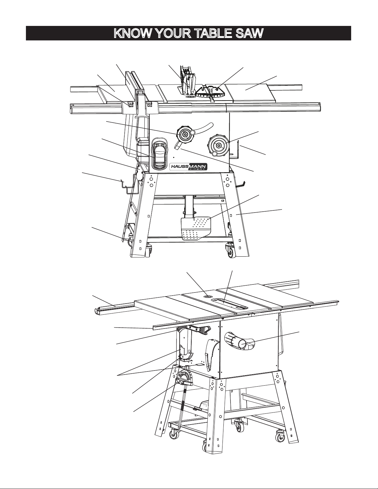
Blade guard
Table extension (right)
Rip fence
ON/OFF switch with key
Blade elevation handwheel
Blade tilting handwheel
Stand
Blade tilt scale
Table extension (left)
Mitre gauge
Power cord storage
Dust port
Rear rail
Mitre gauge storage
Table insert
Anti-kickback pawl storage
Rip fence storage
Pedal
Caster
Front rail
Blade wrench &
push stick storage
Blade guard storage
Blade bevel lock handle
Blade guard storage
KNOW YOUR TABLE SAW
Micro-adjustment rollers

– 12 –
ANTI-KICKBACK PAWLS – Prevents the workpiece
from being kicked upward or back toward the front of the
table saw by the spinning blade.
Arbour – The shaft on which the blade or dado is
mounted.
BEVEL CUT – An angle cut made through the face of
the workpiece.
BLADE BEVEL SCALE – Measures the angle the blade
is tilted when set for a bevel cut.
BLADE ELEVATION AND TILTING HANDWHEEL –
Raises and lowers the blade or tilts the blade to angle
between 0oand 45ofor bevel cuts.
BLADE GUARD – Clear plastic cover that positions
itself over the blade while cutting.
COMPOUND CUT – A simultaneous bevel and mitre
cut.
CROSSCUT – A cut made across the width of the
workpiece.
DADO – Special cutting blades that are used to cut
grooves in a workpiece.
FEATHERBOARD – When ripping a workpiece on your
table saw, this keeps it firmly and safely against the
rip fence. It also helps prevent chatter, gouging, and
dangerous kickback.
FREEHAND – Performing a cut without using a rip
fence, mitre gauge, hold down or other proper device to
prevent the workpiece from twisting during the cutting
operation.
GUM – A sticky sap from wood products.
HEEL – Misalignment of the blade.
JAMB NUT – Nut used to lock another nut in place on a
threaded rod or bolt.
KERF – The amount of material removed by the blade
cut.
KICKBACK – Occurs when the saw blade binds in the
cut and violently thrusts the workpiece back toward the
operator.
MITRE CUT – An angle cut made across the width of
the workpiece.
MITRE GAUGE – A guide used for crosscutting
operations that slides in the table top channels (grooves)
located on either side of the blade. It helps make
accurate straight or angle crosscuts.
NON-THROUGH SAWING - refers to any cut that does
not completely cut through the workpiece.
OVERLOAD RESET SWITCH – Protects the motor if it
overloads during operation, provides a way to restart the
saw.
PUSH STICK – Used to push workpieces when
performing ripping operations.
PUSH BLOCK – Used for ripping operation when the
workpiece is too narrow to use a push stick. Always use a
push block for rip widths less than 2 in. (50.8 mm).
RESAWING - flipping material to make a cut the saw is
not capable of making in one pass.
Resawing IS NOT recommended.
REVOLUTIONS PER MINUTE (RPM) – The number of
turns completed by a spinning object in one minute.
RIP FENCE – A guide used for rip cutting which allows
the workpiece to cut straight.
RIPPING – Cutting with the grain of the wood or along
the length of the workpiece.
RIVING KNIFE – A metal piece of the guard assembly
located behind and moves with the blade. Slightly
thinner than the saw blade, it helps keep the kerf open
and prevents kickback.
SAW BLADE PATH – The area of the workpiece or
table top directly in line with the travel of the blade or the
part of the workpiece that will be cut.
SET – The distance between two saw blade tips, bent
outward in opposite directions to each other. The further
apart the tips are, the greater the set.
TABLE INSERT – Insert that is removed from the table
to install / remove blades. When dado cutting, a dado
insert plate must be used.
THROUGH SAWING – Making a cut completely
through the length or width of a workpiece.
WORKPIECE – Material to be cut.
NOTE: Blade guard assembly is removed for purposes
of illustration only.
GLOSSARY OF TERMS
Leading Edge
Kerf
Surface
Saw Blade Path
Trailing Edge
Workpiece
Direction of Workpiece
WARNING
!

– 13 –
5. Bag “C” - Join the right frame leg and the left frame
leg by using the rear top / bottom leg support (8, 9),
six square neck bolts (11) and six nuts (12).
Fig. C
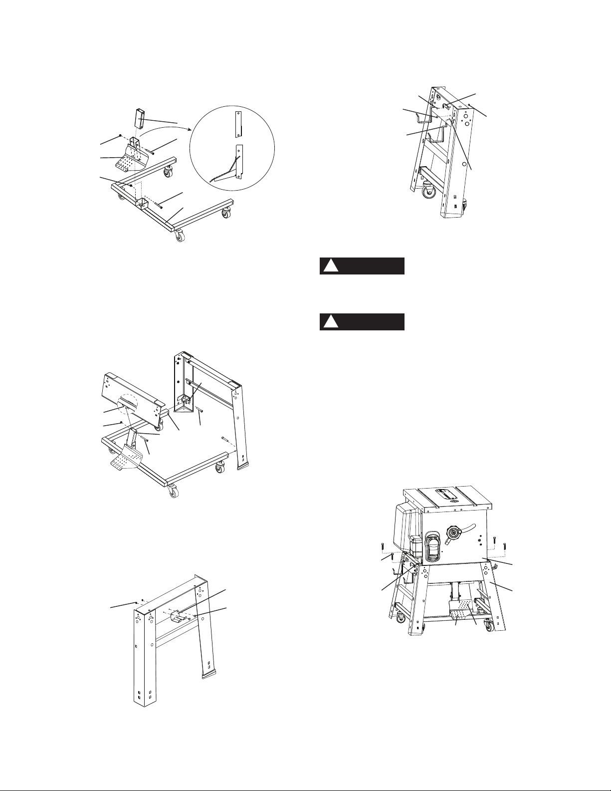
6. Bag “F” - Place three foot pads (13) onto the legs (3,
5, 6), thread the adjustable foot pad with hex nut (14)
into the front right leg (2).
7. Place stand on level surface and adjust, so all legs
are contacting the floor and are at similar angles to
the floor and detents in stand leg align with supports,
then tighten all bolts.
NOTE: Stand should not rock after all bolts are
tightened.
Fig. D
8. Bag “H” - Install the front casters (15) and rear
casters (16) to the bottom of the caster bracket (17).
NOTE: Identify the front casters and rear casters
before installing.
Fig. E
Estimated Assembly Time: 90~120 minutes
(2 people)
For your safety, never connect plug to power
source receptacle until all assembly and
adjustment steps are complete, and you have
read and understood the safety instructions.
ASSEMBLING STAND (FIG. A~I)
1. Unpack all parts and group by type and size.
Refer to parts list for quantities. The number is
labeled on each leg and leg support, please identify
before assembling.
2. Bag “C” - Attach the right top leg support (1) and the
right bottom leg support (10) to the front right leg (2)
and rear right leg (3) with six square neck bolts (11)
and six nuts (12) to complete right frame leg.
NOTE:
Do not tighten bolts until stand is properly
aligned.
Position all supports to the INSIDE of the leg
assembles.
Align detents (13) in stand leg with supports to
ensure proper fit.
3. Repeat above steps for the left frame leg - left top leg
support (4), the left bottom leg support (10), front left
leg (5) and rear left leg (6).
Fig. A
4. Bag “C” - Join the right frame leg and the left frame
leg by using the front leg support (7), four square
neck bolts (11) and four nuts (12).
Fig. B
ASSEMBLY AND ADJUSTMENTS
16
17
15
WARNING
!
Front
Front
2
13
1
12
11
3
10
12
11
7
Front
6
4
5
10
9
8
12 11
13
Front
2
3
5
6
14
– 14 –
9. Bag “I” - Mount the pedal (1) to the caster bracket
(2) by using the longest bolt (3) and nut (4), and
attach the link (5) to pedal (1) with bolt (6) and nut (4)
by 6 mm hex key supplied.
Fig. F
10.Bag “I” - Attach the left / right rear tubes (8) of caster
bracket into the brackets (9) of the rear legs by
using two short bolts (10). Attach the link (5) into the
bracket (11) with bolt (6) and nut (4).
NOTE: Do not over tighten bolts. The caster
assembly will be difficult to operate if the bolts are
too tight.
Fig. G
NOTE: The front right / left legs have been removed
from this drawing for illustration purposes only.
11.Bag “J, K” - Attach mitre gauge storage (12) to the
right leg support by using two short screws (14) and
nuts (15).
Fig. H
12.Bag “J, K” - Attach power cord storage (16) to the
left leg support by using two long screws (18) and
nuts (15).
9
810
6
11
45
13.Insert the rip fence storage (20) into slots (21) of the
left leg support, tighten by using two of six screws
(22).
Fig. I
NOTE: Make sure all screws and nuts are tight and
stand is on a stable surface before mounting saw.
Although compact, this saw is heavy and should be
lifted with care. Get the assistance of someone to lift
and move the saw.
For your safety, never connect plug to power source
receptacle until all assembly and adjustment steps are
complete, and you have read and understood the safety
instructions.
ASSEMBLING TABLE SAW TO STAND (FIG. J)
1. Lift the saw body (1) and place on the stand (2), align-
ing the mounting grooves (3) of the saw base with the
four mounting holes on the top plate of stand.
2. Bag “P” - Attach the table saw to the stand with four
hex head bolts (4).
3. Tighten all mounting bolts with a wrench.
Fig. J
OPERATING ONE STEP CASTER STAND SYSTEM
(FIG. J)
1. Step on the bottom of pedal (5) with your foot to lift
saw off ground. Make sure pedal locks in place.
2. Move saw to the desired location.
3. Press against the top of pedal (6) with your foot to
release the pedal and lower the saw to the ground.
NOTE: Table Saw assembly is heavy, make sure the
ground is level and free of obstructions.
WARNING
!
4
3
1
2
5 6
WARNING
!
14
12
15
21
16
18
22
20
15
5
6
3
2
4
1
4
right side
view
– 15 –
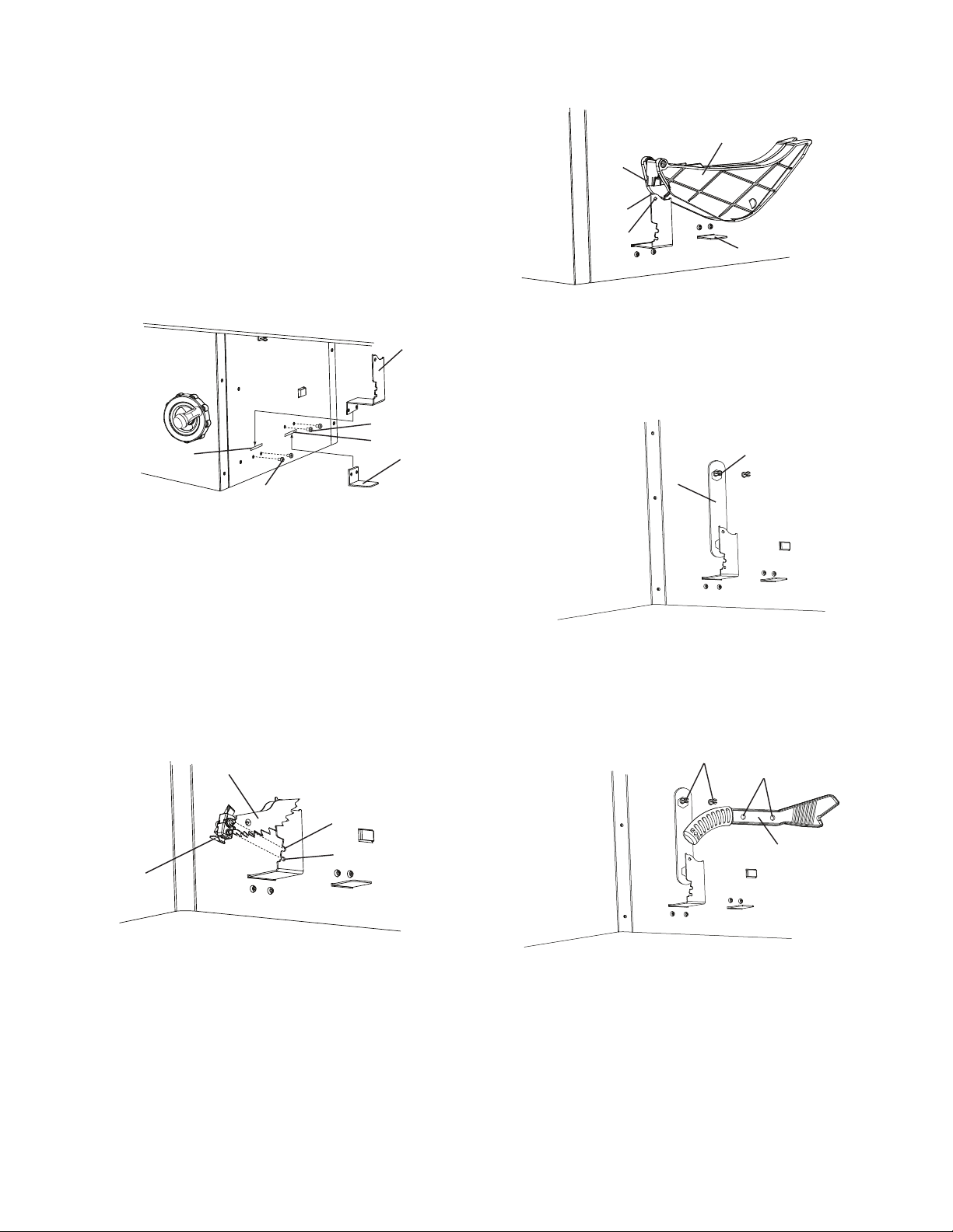
INSTALLING THE ANTI-KICKBACK PAWL AND
BLADE GUARD ASSEMBLY STORAGE (FIG. K)
Storage brackets for anti-kickback pawl and blade guard
assembly are located on the right side of the saw base.
1. Bag “J, K” - Insert the bracket (1) into the left slot (2)
on the right side of saw base, attach the brackets by
using two of six screws (22).
2. Bag “J, K” - Insert the support plate (4) into the right
slot (5), attach the support plate by using two of six
screws (22).
Fig. K
STORAGE (FIG. L ~ R)
Anti-kickback pawl storage (Fig. L)
Storage brackets for anti-kickback pawl (1) are located
on the right side of the saw base.
1. Take the anti-kickback pawl assembly (1) and lift up
the locking lever (2) located on top.
2. Place the front of assembly into slot (3) and push
down making sure the assembly is engaged in the slot
(3, 4). There should be no movement of the assembly.
Push down on the locking lever.
Fig. L
Blade guard assembly storage (Fig. M)
Storage brackets for blade guard assembly (1) are
located on the right side of the saw base.
1. Take the blade guard assembly (1) and locate the
sliding locking knob (2) on the back of assembly.
2. Slide the locking knob up and press the guard
assembly down along the step (3) so that the ball
engages into hole (4) completely.
3. Release the locking knob. Make sure that the
assembly is locked in place and supported by plate (5).
Fig. M
Blade wrench & push stick storage (Fig. N, O)
Storage for blade wrench and push stick is located on
the right side of the saw base.
1. Hang the blade wrench (1) on the holder (2) as
shown.
Fig. N
2. Insert the holders (2) through the holes (3) of the
push stick (4).
Fig. O
Riving knife storage (Fig. P)
Storage for riving knife (1) is located on the right side of
the saw base. Insert the riving knife through the holder
(2) as shown.
1
4
22
5
2
22
3
4
1
2
1
2
23
4
1
4
2
3
5

– 16 –
Fig. P
Mitre gauge storage (Fig. Q)
Storage for mitre gauge (1) is located on the right side
of the stand. Hang the mitre gauge on the hook (2).
Fig. Q
Rip fence storage (Fig. R)
Storage brackets for the rip fence (1) are located on
the left side of the stand. Place the rip fence on the two
hooks (2).
Power cord storage (Fig. R)
Storage for the power cord (3) is located on the left side
of the stand. Wrap the power cord onto the brackets (4)
when saw is not in use. This can prevent damage to the
cord.
Fig. R
2
1
2
1
3
4
ASSEMBLING THE TABLE EXTENSION (FIG. S)
1. Place the left table extension next to the saw
table, aligning the mounting holes (1).
2. Bag “Q” - Place three bolts with washers (2) and
thread in mounting holes.
3. Place a straight edge or combination square on
the saw table, across the table extension.
4. Adjust the mounting bolts (2) until the extension
is flush with the saw table, and tighten.
NOTE: Extensions will not be flush on outer edges at
this time until rails are installed.
5. Repeat these procedures for the right table
extension.
Fig. S
ASSEMBLING THE FRONT AND REAR TABLE RAIL
(FIG. T, U)
Assembling the front rail (Fig. T)
1. Identify the right front rail (1) and the left front rail (2)
by rail scales (3).
2. Bag “R” - Attach the right front side cover (4) into
right front table rail (1). Repeat for the left front rail.
3. Bag “S” - Place four long hex bolts (5), two short hex
bolts (6) through the holes at the front table edge.
Screw the square nuts (7) onto each bolts.
NOTE: Keep the bolts and square nuts loosened
before attaching front rail.
4. Attach the right front rail onto proper location by
having the square nuts pass through the slot of the
front rail. Repeat for the left front rail.
5. Attach the middle plug (8) to connect the two front rail
halves.
6. With the blade installed, use the rip fence and gauge
to adjust the front rail to proper location. When the
front rail is level with table, then fix the front rail by
tightening the six bolts. NOTE: Place straight edge
across table and extension and lift rail until edge is
flush, then tighten bolts. Repeat for other side.
Fig. T
2
1
0
101
2
1
3
5
5
7
6
6
4
8
1
2

– 17 –
Assembling the rear rail (Fig. U)
1. Identify the right rear rail (1) and the left rear rail (2).
2. Place the rear rail on the saw table, aligning
with the holes in each rail.
3. Bag “T” - Place six hex bolts (3), two nuts (4) and
thread into the holes; tighten the bolts and check the
alignment again.
Fig. U
BLADE TILTING HANDWHEEL (FIG. V)
1. Bag “U” - Attach the blade tilting handwheel (1) to
the tilting shaft (2) at the front of the saw.
2. Attach and tighten the dome nut (3) at the end of the
shaft.
BLADE ELEVATION HANDWHEEL (FIG. V)
1. Insert the hex nut (4) into the hole (5) located on the
rear of the blade elevation handwheel (6), thread the
handle (7) into the handwheel (6) and tighten.
Fig. V
REMOVING THE BLADE (FIG. W)
To avoid injury from an accidental start, make sure
the switch is in the OFF position and the plug is
disconnected from the power source outlet.
1. Remove the table insert and raise the blade to the
maximum height by turning the blade elevation
handwheel clockwise.
NOTE: there is a “finger hole” in the insert that is
used for removing the insert.
2. Adjust the blade to the 0overtical position by
unlocking the blade tilting lock handle and turning the
blade tilting handwheel counterclockwise, and then
lock into position.
WARNING
!
23
3
4
1
1
2
3
4
5
76
3. Pull the motor locking lever (1) toward the front of the
machine while spinning the blade until the latch locks
into place and the blade will no longer turn.
4. Place the blade wrench (2) on the arbour nut (3).
5. Loosen and remove the arbour nut and the flange
(4) by pulling the wrench toward the front of the
machine.
6. Then remove the blade (5). Clean but do not remove
the inner blade flange before reassembling the
blade.
Fig. W
INSTALLING A BLADE (FIG. W)
To avoid injury from an accidental start, make sure
the switch is in the OFF position and the plug is
disconnected from the power source outlet.
1. Place the blade (5) onto the arbour (6) with the blade
teeth pointing forward to the front of the saw.
2. Make sure the blade fits flush against the inner
flange.
3. Clean the outer blade flange (4) and install it onto the
arbour and against the blade.
4. Thread the arbour nut (3) onto the arbour, making
sure the flat side of the nut is against the blade, then
hand-tighten.
5. Pull the motor locking lever (1) toward the front of the
tool while spinning the blade until the latch locks
into place and the blade will no longer turn.
6. Place the wrench (2) on the arbour nut and turn
clockwise (toward the rear of the saw table).
7. Replace the table insert.
ADJUSTING THE 0°AND 45°POSITIVE STOPS
(FIG. X, Y, Z)
Your saw has positive stops that will quickly position the
saw blade at 0° and 45° to the table. If adjustments
are necessary to these positive stops, please use the
instructions on the next page.
WARNING
!
2
3
5
1
4
6

– 18 –
0° Stop (Fig. X, Y)
1. Disconnect the saw from the power source.
2. Turn the blade tilting handwheel until the blade tilting
scale is at 0°.
3. Turn the blade elevation handwheel and raise the
blade (1) to the maximum elevation.
4. Place a combination square (2) on the table and
against the blade to check if the blade is 0° to the
table.
Fig. X
5. If the blade is not 0° to the table: remove the back
cover of the base by removing the screws, two for
each side.
6. Adjust the blade tilting handwheel to make an
adequate distance between the anchor block (1) and
bevel gear (2). (Fig. Y)
7. Loosen the two set screws (3) of the anchor block
with 3 mm hex key.
8. Separate the anchor block (1) from the worm (4).
When the bevel angle is more than 0°, turn the
anchor block in the A direction until the bevel
angle and bevel scale are the same.
When the bevel angle is less than 0°, turn the
anchor block in the B direction until the bevel
angle and bevel scale are the same.
9. When completing the above adjustment, replace the
set screws and tighten them.
10.Replace the back cover and then tighten the screws.
Fig. Y
AB
2
1 3 4
1
2
0° 45°
45oStop (Fig. X, Z)
1. Turn the blade tilting handwheel until the blade tilting
scale is 45°.
2. Turn the blade elevation handwheel and raise the
blade to the maximum elevation.
3. Place a combination square on the table and against
the blade to check if the blade is 45° to the table.
4. If the blade is not 45° to the table: remove the back
cover of the base by removing the screws, two for
each side.
5. Adjust the blade tilting handwheel to make an
adequate distance between the anchor block (1) and
bevel gear (2).
6. Loosen the two set screws (3) of the anchor block
with 3 mm hex key.
7. Separate the anchor block from the worm (4).
When the bevel angle is more than 45°, turn the
anchor block in the A direction until the bevel angle
and bevel scale are the same.
When the bevel angle is less than 45°, turn the
anchor block in the B direction until the bevel angle
and bevel scale are the same.
8. When completing the above adjustment, replace the
set screws and tighten them.
9. Replace the back cover and then tighten the screws.
Fig. Z
BLADE TILTING INDICATOR (FIG. AA)
NOTE: This is located on the top of the table, in front of
the blade guard
1. When the blade is positioned at 0°, adjust the blade
tilt pointer to read 0° on the scale.
2. Remove the magnifier cover (1) by removing the two
screws (2). Position the pointer over 0° and replace
the magnifier cover and replace the screws
NOTE: Make a trial cut on scrap wood before making
critical cuts. Measure for accuracy.
Fig. AA
BA
4
2
13
0
510
2
1
– 19 –
INSTALLING THE TABLE INSERT (FIG. BB, CC)
NOTE: The table saw is sold with the table insert
pre-installed. However, you must verify that the table
insert is flush with the table top surface on all four
corners of the insert.
1. Insert the spring clip (1) under the table, and push
the table insert (2) to be flush with the table.
2. If the table insert is not flush with the table, adjust the
four screws (3) with a screwdriver until it is flush with
the table.
NOTE: To raise the insert, turn the screws
counterclockwise, to lower the insert, turn the
screws clockwise.
Fig. BB
Fig. CC
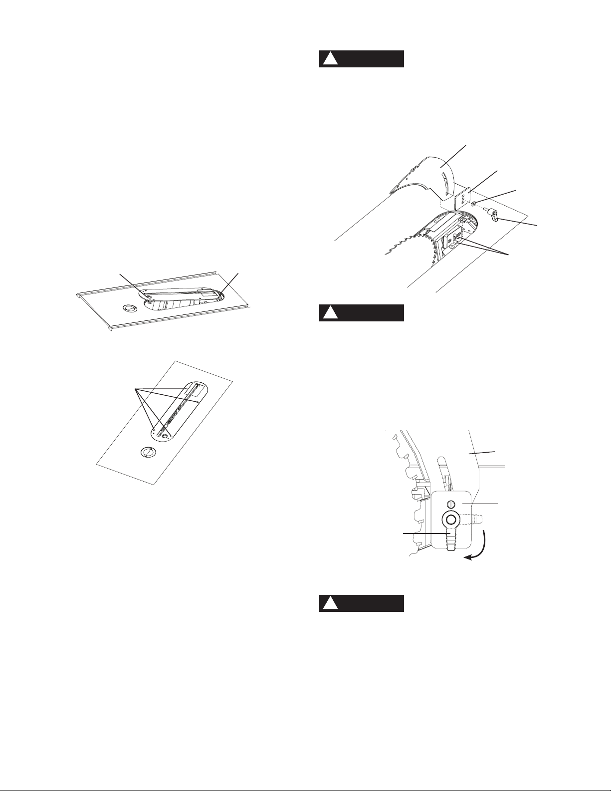
INSTALLING THE RIVING KNIFE (FIG. DD, DD-1)
1. Remove the table insert.
2. With the blade elevation handwheel, raise the blade
arbour to the maximum height.
3. Turn the blade tilting handwheel until the blade tilting
scale is at 45°.
4. Take the lock lever (1) and insert through the washer
(2), middle hole in the set plate (3) and slot on the
riving knife (4).
5 . Place this assembly through the mounting bracket
located behind the saw blade. Please note that the
two pins (5) on the bracket must be engaged in the
riving knife slot and two holes in the set plate.
6. Tighten the lock lever (1).
7. Return the blade to 0° and place the table insert in
position.
12
3
Before connecting the table saw to the power source
or operating the saw, always inspect the blade guard
assembly and riving knife for proper alignment and
clearance with saw blade. Check alignment after each
change of bevel angle.
Fig. DD
To avoid the lock lever interferring the table
insert, after tighten the riving knife, position the
lock lever pointing downward before using saw.
Failure to maintain a level insert can result in
serious injury to the operator.
The lever can be pulled out to allow for placement
in the down position without loosen the lock.
(Fig. DD-1)
Fig. DD-1
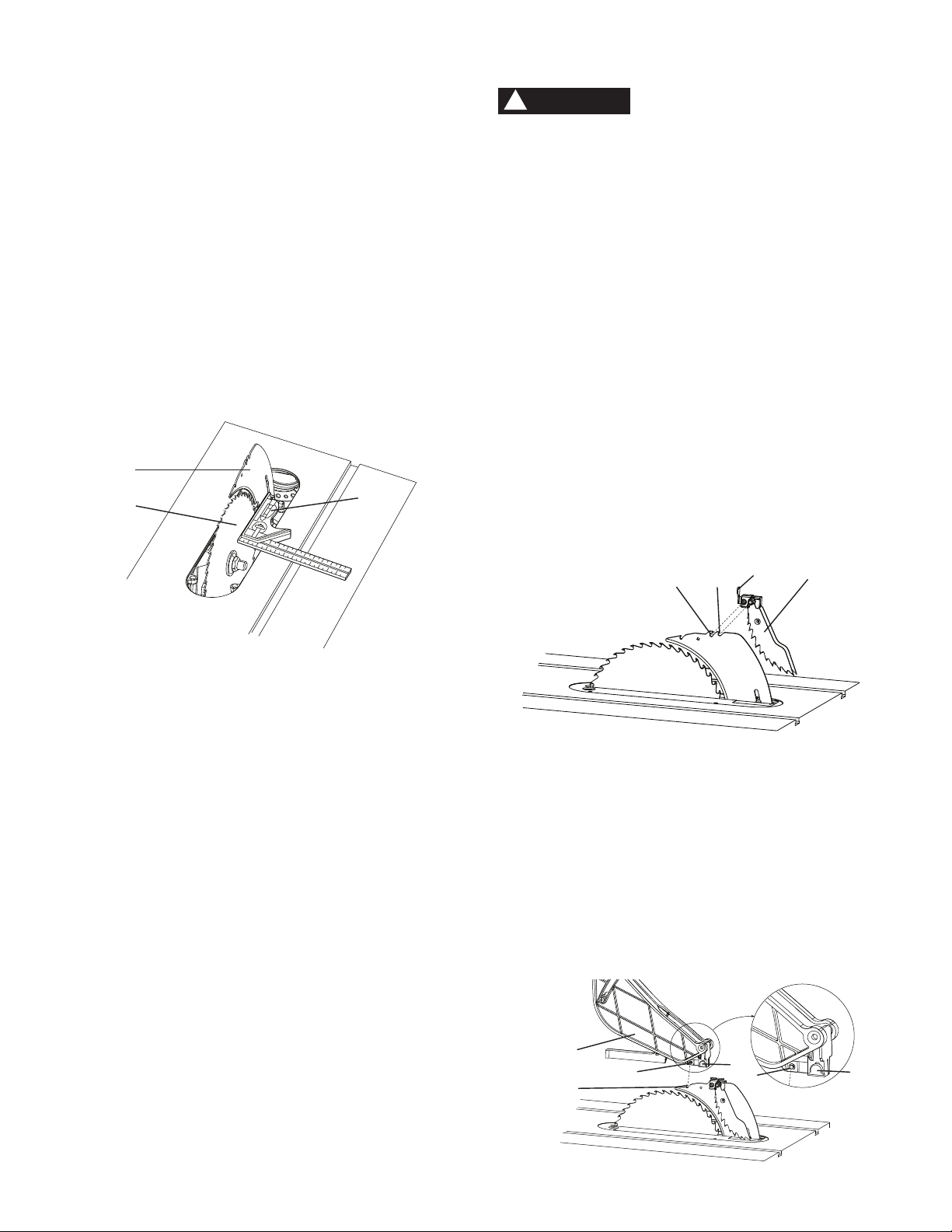
ALIGNING THE RIVING KNIFE TO BLADE
(FIG. DD, EE)
To avoid injury from an accidental start, make
sure the switch is in the OFF position and the
plug is disconnected from the power source
outlet.
Never operate this tool without the riving knife in
the correct position.
Never operate this tool without the blade guard in
place for all through sawing operations.
This adjustment was made at the factory, but it
should be rechecked and adjusted if necessary.
WARNING
!
4
5
2
1
3
WARNING
!
WARNING
!
1
4
3
– 20 –
1. Remove the table insert and raise the blade to the
maximum height by turning the blade elevation
handwheel clockwise.
2. Remove the blade guard and anti-kickback pawl
assembly.
3. Adjust the blade to the 0° vertical position by unlocking
the blade tilting lock handle and turning the bevel
tilting handwheel counterclockwise, and then lock into
position.
4. To see if the blade (1) and riving knife (2) are
correctly aligned, lay a combination square (3) along
the side of the blade and against the riving knife
(making sure the square is between the teeth of the
blade).
5. Tilt the blade to the 45° position and check the
alignment again.
Fig. EE
NOTE:
This table saw is provided with a 10 in. diameter
blade with a body thickness of 0.07 in. (1.8 mm) thick
and a kerf of 0.1 in. (2.6 mm). The riving knife is
0.09 in. (2.2 mm) thick. The blade diameter and the
blade body and kerf dimensions must be properly
matched with the riving knife thickness.
The maximum radial distance between the riving
knife and the toothed rim of the saw blade is 0.12 in
~ 0.31 in. (3 mm ~ 8 mm).
The tip of the riving knife shall not be lower than 0.04
in. ~ 0.2 in. (1 mm ~ 5 mm) from the tooth peak.
The riving knife is thinner than the width of the kerf
by approximately 1/64 in. (0.4 mm) on each side.
The blade body must be thinner than the thickness
of the riving knife but the blade kerf must be thicker
than the riving knife.
3
2
1
INSTALLING BLADE GUARD ASSEMBLY (FIG. FF, GG)
To avoid injury from an accidental start, make sure
the switch is in the OFF position and the plug is
disconnected from the power source outlet.
When installing the blade guard, cover the blade
teeth with a piece of folded cardboard to protect
yourself from possible injury.
Never operate this saw without the blade guard
in place for all through sawing operations.
Installing the anti-kickback pawl and blade guard
assembly (Fig. FF)
1. Make sure the blade is elevated to its maximum
height and the bevel is set at 0°. Make sure the bevel
lock handle is tight.
2. Take the anti-kickback pawl assembly (1) and lift up
the locking lever (2) located on top.
3. Place the front of assembly into slot (3) and push
down making sure the assembly is engaged in the slot
(3, 4). There should be no movement of the assembly.
Push down on the locking lever.
Fig. FF
4. Take the blade guard assembly (5) and locate the
sliding locking knob (6) on the back of assembly.
5. Insert the blade guard assembly onto the riving knife
so that the pin (7) engages into slot (8) completely.
6. Slide the locking knob (6) up and press the guard
assembly down so that the entire assembly is flat on
the riving knife. Release the locking knob.
7. Make sure that the assembly is locked in place both in
front and back.
Fig. GG
WARNING
!
6
5
7
8
6
7
1
2
43
This manual suits for next models
1
Table of contents
Other Haussmann Xpert Saw manuals


