10
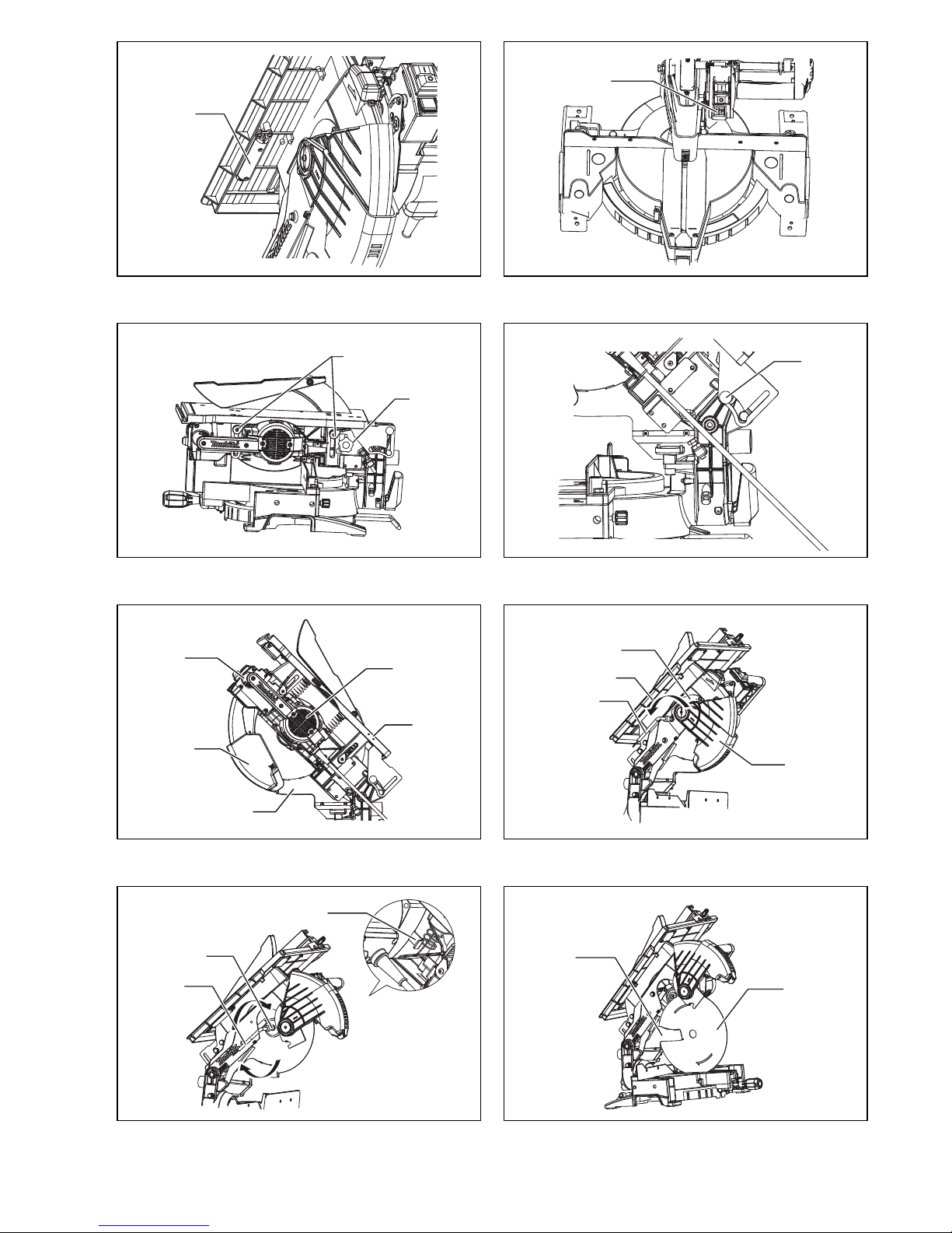
• To avoid injury from flying debris, keep holding the saw head down, after making cuts, until the
blade has come to a complete stop.
• Pour éviter les blessures causées par les objets projetés, maintenez la tête de la scie en position
basse une fois la coupe terminée, jusqu’à ce que la lame soit complètement arrêtée.
• Um Verletzungen durch herausgeschleuderte Teile zu vermeiden, halten Sie den Sägekopf nach
Ausführung von Schnitten abgesenkt, bis das Sägeblatt völlig zum Stillstand gekommen ist.
• Per evitare lesioni dalle schegge volanti, dopo aver eseguito il taglio tenere abbassata la testa
sega finché la lama non si è arrestata completamente.
• Om verwonding door weggeslingerd zaagafval te voorkomen, dient u na het voltooien van een
snede de zaagkop omlaag te houden totdat het zaagblad volledig tot stilstand is gekomen.
• Para evitar sufrir heridas a causa de restos que salen despedidos, siga sujetando la cabeza de la
sierra hacia abajo, al terminar los cortes, hasta que el disco se haya parado completamente.
• Para evitar danos causados por aparas que saltem, mantenha a cabeça da serra para baixo,
depois de terminar os cortes, até que a lâmina esteja completamente parada.
• For at undgå at komme til skade på grund af flyvende affald, skal man holde savhovedet nede efter
skæring, indtil savklingen står helt stille.
•Για να αποφύγετε τραυματισμό από ιπτάμενα τεμαχίδια, κρατάτε το πριόνι με το κεφάλι προς τα
κάτω, αφού κάνετε κοπές, μέχρι ηλάμα να σταματήσει τελείως.
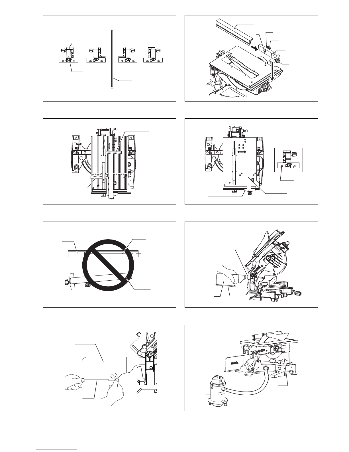
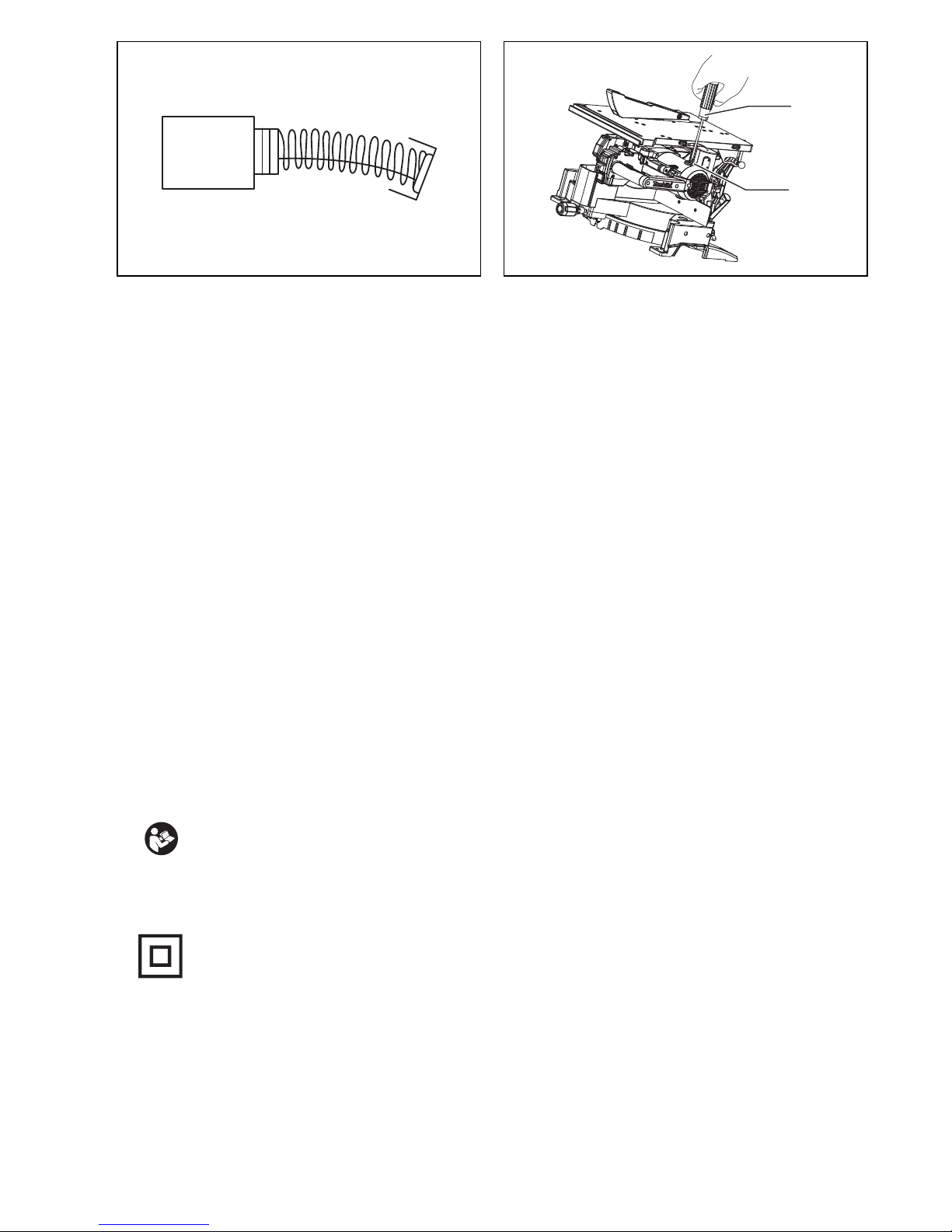
• When using the tool in the miter saw mode, secure the top table at the topmost position so that the
saw blade never protrudes from the top surface of the top table.
• Pour utiliser l’outil en mode de scie à coupe d’onglet, fixez la table supérieure à la position la plus
élevée, de sorte que la lame ne dépasse jamais la surface supérieure de la table supérieure.
• Wenn Sie die Maschine im Gehrungssägenmodus verwenden, sichern Sie den oberen Tisch in der
Höchststellung, damit das Sägeblatt nicht über die Oberfläche des oberen Tisches hinausragt.
• Quando si usa l’utensile nella modalità di sega a unghia, fissare il piano superiore sulla posizione
più alta in modo che la lama non sporga mai dalla superficie superiore del piano superiore.
• Voor gebruik van het gereedschap als verstekzaag dient u de boventafel in de hoogste stand vast
te zetten, zodat het zaagblad nooit uitsteekt voorbij de bovenkant van de boventafel.
• Cuando utilice la herramienta en el modo de sierra de inglete, sujete la mesa superior en la
posición máxima superior sin que el disco sobresalga nunca por la parte superior de la mesa
superior.
• Quando utiliza a ferramenta no modo de serra de esquadria, prenda a mesa superior na posição
mais elevada de modo a que a lâmina nunca fique saliente da superfície superior da mesa supe-
rior.
• Når maskinen anvendes i geringssav-indstilling, skal det øverste bord sikres i den øverste stilling,
således at savklingen ikke på noget tidspunkt stikker frem fra overfladen på det øverste bord.
•Όταν χρησιμοποιείτε το εργαλείο σε θέση λειτουργίας λοξού πριονιού, ασφαλίστε το άνω τραπέζι
στην ανώτερη θέση ώστε ηλάμα πριονιού να μην προεξέχει ποτέ από την άνω επιφάνεια του άνω
τραπεζιού.
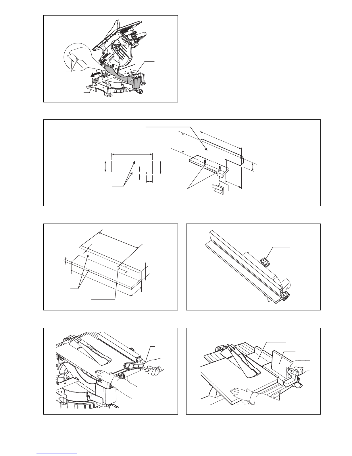
• Do not place hand or fingers close to the blade.
• Ne pas placer les mains ou les doigts près de la lame.
• Halten Sie Hände oder Finger vom Sägeblatt fern.
• Non avvicinare le mani o le dita alla lama.
• Kom met uw handen of vingers niet te dicht bij het zaagblad.
• No ponga la mano ni los dedos cerca del disco.
• Não coloque a sua mão ou dedos perto da lâmina.
• Hold hænder og fingre på god afstand af klingen.
•Μη βάζετε το χέρι ήτα δάκτυλα κοντά στην λάμα.
• For your safety, remove the chips, small pieces, etc. from the table top before operation.
• Pour votre sécurité, retirez les copeaux et autres petites pièces présentes sur la table avant de
commencer le travail.
• Zur Sicherheit sollte die Tischplatte vor dem Betrieb von Spänen, Kleinteilen usw. gesäubert wer-
den.
• Per la propria sicurezza, togliere i trucioli, frammenti, ecc., dalla superficie superiore del piano di
taglio prima di procedere.
• Verwijder voor uw eigen veiligheid zaagafval, stukjes hout e.d. van de werktafel alvorens te gaan
zagen.
• Por su propia seguridad, retire las virutas, trozos pequeños, etc., de encima de la mesa de trabajo
antes de iniciar la tarea.
• Para sua segurança, retire aparas, peças pequenas, etc., de cima da bancada antes da operação.
• Af sikkerhedsårsager skal spåner, små stykker etc. fjernes fra bordtoppen inden anvendelsen.