HAUTAU ZV/R Service manual

Montage- und
Betriebsanleitung
Zusatzverriegelung ZV/R
Mounting and
operating instructions
Additional locking ZV/R
Warnung
Gefährdung für Material
durch falsche Handhabung.
Danger of material damage
due to incorrect handling.
Sicherheitshinweise Safety instructions
Montage und Installation nur von sachkundigem und sicherheits-
bewusstem Fachpersonal. Lesen und beachten Sie die Angaben
in dieser Montage- und Bedienungsanleitung, um Schäden und
Gefahren zu vermeiden.
Diese Anleitung ist für späteren Gebrauch/Wartung aufzubewahren.
Vor Wartungsarbeiten Netz abklemmen und vor unsachgemäßem
Wiederein schalten sichern. Montage, Leitungsverlegung und An schluss
nur durch zu gelassene Fach firmen. Bei der Installation die einschlägigen
Vorschriften (z.B.: VDE 0833/0815, ZH 1/494) beachten. Die Wartungs-
und Bedienvorschriften für kraftbetätigte Fenster, Türen und Tore
ZH 1/494 sind zu beachten.
Zusatzverriegelung nur mit HAUTAU-Steuerungen betreiben - nur so
kann eine Funktions garantie gewähr leistet werden. Bei Ver wendung von
Fremd fabrikaten keine Service- oder Garantie leistungen.
Es sind flexible Zuleitungen zu verwenden (nicht ein putzen). Bei der
Verlegung sind Beschä dig ungen durch Quetschung, Biegung und Zug
zu verhindern.
Leitungen so kurz wie möglich verlegen, die Leitungen zu den Antrieben
sind in Abzweigdosen zu verklemmen. Abzweigdosen sind für
Wartungsarbeiten zugänglich zu machen. Kabeltypen mit der örtlichen
Abnahme behörde festlegen (Feuerwehr, Brand schutzbehörde, TÜV etc).
Netz- und Akku-Anschluss erst nach Montage prüfung und Probelauf
durchführen.
Den Antrieb vor Bauschmutz und Feuchtigkeit schützen.
Sicherheitsrelevante Bauteile sind regelmäßig auf festen Sitz zu über-
prüfen und auf Verschleiß zu kontrollieren. Je nach Erfordernis sind die
Befestigungsschrauben nachzuziehen bzw. die Teile auszutauschen.
Defekte Motoren dürfen nicht geöffnet werden (Garantieverlust) und sind
zur Reparatur ans Werk zu schicken.
Achtung:
Die Montage und Installation hat sach gemäß, sicherheits bewusst und
nach An gaben der Anschlaganleitung zu erfolgen. Werden Ersatzteile,
Ausbauteile oder Erweiterungen benötigt, aus schließlich Original-
Ersatzteile verwenden.
Für eine ausreichende Befestigung der Beschlagteile ist zu sorgen.
Mounting and installation has to be performed by trained, qualified
and safety-conscious electrical staff. Read and consider details
within these instructions to avoid damages and hazards.
These instructions should be kept for future use / maintenance.
Before servicing work, disconnect power supply and secure against
improper reconnection.
Installation, wiring and connection only by licensed companies.
During installation, observe relevant regulations (e. g. VDE 0833/0815).
The maintenance and operating instructions for power-operated
windows, doors and gates, ZH 1/494, must be observed, too.
Additional locking has to be operated with HAUTAU controls, only. This
is the only way to guarantee function. No service or warranty in case of
using third-party products.
Flexible wiring must be used (do not plaster in). During installation, avoid
damage due to pinching, twisting and pulling.
Lay wiring as short as possible, clamping the lines to the drives in
branch boxes.
Branch boxes must be readily accessible for servicing work.
Determine types of cables with the local inspection authorities (fire brigade,
fire-protection authority, technical supervisory authority, etc).
Mains and rechargeable-battery connections after assembly inspection
and trial run, only.
Protect drive from dirt and humidity.
Safety-related components should be checked regularly for tightness
and wear. Depending on the requirements, the fastening screws have to
be retightened or the parts have to be replaced.
Defective drives must not be opened (loss of warranty) and have to be
sent to works for repair.
Attention:
Assembly and installation must be carried out in a proper and safety-
conscious manner in keeping with the details of the instructions.
If replacement parts, extension elements or enlargements are required,
use original parts only. Ensure adequate fastening of the fitting parts.
0 3 / 2 013 16 7 9 8 4 D
t
D
Achtung Lebensgefahr:
Die Zusatzverriegelung nur mit
24 V DC betreiben, niemals an
230 V AC anschließen.
Danger to life:
Operate the additional locking with
24 V DC, only; never connect to
230 V AC.
Warnung
Gefährdung für Personen durch
Ge fahren aus dem Gerätebetrieb.
Danger of personal injury during
operation of device.
Bei Wartungsarbeiten Netz abklemmen
und vor unsachgemäßem Wieder-
einschalten sichern.
Before servicing work, disconnect
power supply and secure against
improper reconnection.
Quetsch- und Klemmgefahr:
Bei der Montage und Bedienung nicht
in den Fensterfalz und in die Zusatz-
verriegelung greifen.
During assembly work and operation,
do not reach into the window rabate
or into the additional locking.
2
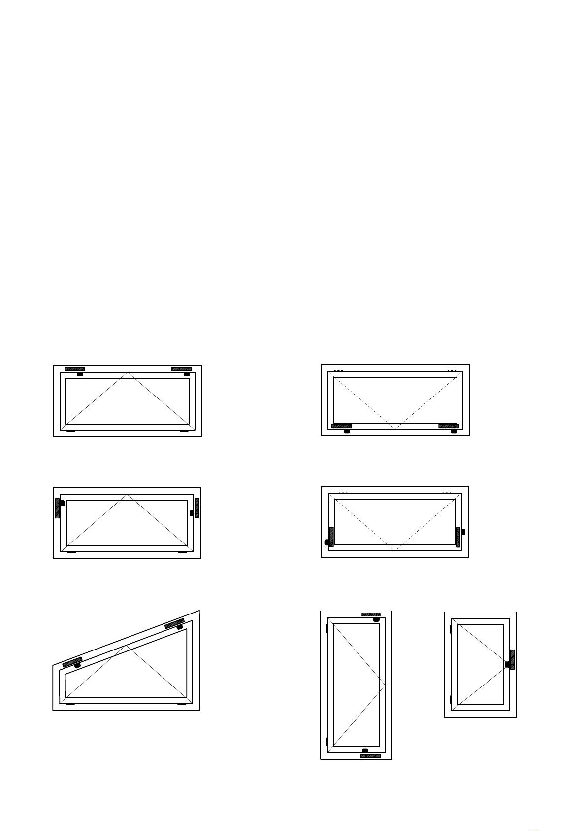
Anwendungsbeispiele / Application examples
Kippflügel einwärts, Montage oben
Bottom-hung open in sash, mounting top Klappflügel auswärts, Montage unten
Top-hung sash outwards opening, mounting bottom
Klappflügel auswärts, Montage seitlich
Top-hung outwards opening sash, mounting laterally
Schrägfenster einwärts, Montage oben
Inclined open in window, mounting top Drehflügel einwärts,
Montage seitlich
Side-hung open in sash,
mounting laterally
Drehflügel einwärts,
Montage oben und unten
Side-hung open in sash,
mounting top and bottom
Kippflügel einwärts, Montage seitlich
Bottom-hung open in sash, mounting laterally
Technische Daten
Nennspannung 24 V DC
Spannungstoleranzbereich -20% / + 30%
Restwelligkeit 10 %
Stromaufnahme 0,3 A
Anlaufstrom 0,75 A
Maximaler Andruck 200 N
Zuhaltekraft 900 N
Verschlussmechanik Zinkdruckgussriegel
Laufzeit 4 s
Einschaltdauer 60 s ein / 60 s aus
Umgebungstemperatur 0 °C bis +70 °C
Schutzart IP 54
Abschaltung auf / zu integr. elektronische Lastabschaltung
Anschlusstechnik Anschlussleitung mit motorseitigem
Stecker - 1,8 m
Abmessungen (B x H x T) 197 x 36 x 48 mm
Gewicht ca. 0,9 kg
Lebensdauer (Zyklen Auf / Zu) 11.000
Platzbedarf einwärts Blendrahmen 42 mm
Flügel 50 mm
Platzbedarf auswärts Blendrahmen 50 mm
Flügel 45 mm
Schraubenbedarf Alu/Kunststoff Ø 4,2
Holz Ø 4,0
Zusatzverriegelung variabel auf Überschlaghöhe von
0...10 mm (mit Distanzplatte Pos. 2) bei Aluminium,
12...22 mm bei Holz- und Kunststoff einstellbar
Rated voltage 24 V DC
Voltage tolerance range -20% / + 30%
Remaining ripple 10 %
Current consumption 0,3 A
Starting current 0,75 A
max. pressure 200 N
Locking force 900 N
Locking mechanism zinc mould locking bar
Running period 4 s
Duty cycle 60 s on / 60 s off
Ambient temperature 0 °C to +70 °C
Protection class IP 54
cutoff open / close integrated electronic overload cutoff
Connection technology lead wire with plug on the motor side - 1,8 m
Dimensions (W x H x D) 197 x 36 x 48 mm
Weight approx. 0,9 kg
Lifespan (Open/Closed cycles) 11.000
required space inwards Frame 42 mm
Sash 50 mm
required space outwards Frame 50 mm
Sash 45 mm
Screws needed Alu/PVC Ø 4,2
Timber Ø 4,0
Additional locking is variable adjustable to overrebate height:
0-10 mm (with spacer pos. 2) for aluminium,
12-22 mm for timber and PVC
Technical data
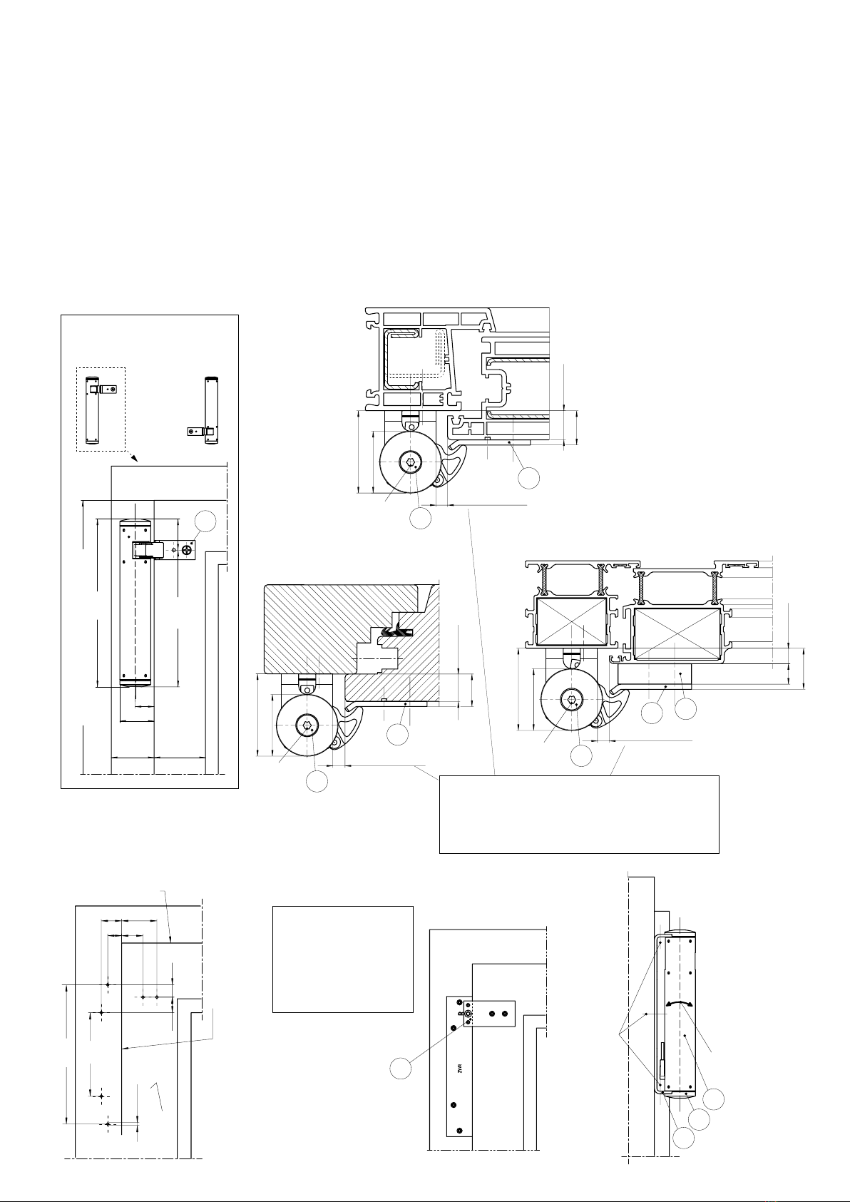
Zusatzverriegelung am
Kippflügel einwärts
Additional locking at
bottom-hung open in sash
Montage
- Befestigungslöcher bohren (ggf. mit optionaler Bohrschablone, Pos. 3)
- Halter (Pos. 1.1) auf den Blendrahmen und Druckstück (Pos. 1.2),
ggf. inkl. Distanzplatte (Pos. 2), auf den Fensterrahmen schrauben
Maß x, bei Holz und Kunststoff: Überschlaghöhe + 3 mm
Maß x, bei Aluminium: Überschlaghöhe + 15 mm
(inkl. 12 mm Distanzplatte Pos. 2)
- Gehäuse (Pos. 1.3) in den Halter (Pos. 1.1) einführen
- Je einen Deckel (Pos. 1.4) stirnseitig aufstecken, Einbaulage beachten
und Schrauben (Pos. 1.5) befestigen (* riegelseitig Linksgewinde!)
Andruckeinstellung im ausgefahrenen/verriegelten
Zustand:
- Lösen der Schrauben (Pos. 1.5)*
- Drehen des Gehäuses (Pos. 1.3) auf das Maß x
- Festziehen der Schrauben mit 10 Nm (Pos. 1.5)*
Mounting
- bore fastening holes (possibly with optional drilling jig, pos. 3)
- fasten bracket (pos. 1.1) onto the window frame and thrust piece
(pos. 1.2), possibly incl. spacer (pos. 2), onto the sash frame
dim. x, for timber and PVC: overrebate height + 3 mm
dim. x, for aluminium: overrebate height + 15 mm
(incl. 12 mm spacer pos. 2)
- install housing (pos. 1.3) into the bracket (pos. 1.1)
- attach one cover (pos. 1.4) each per face side, observe mounting
orientation and fasten screws (pos. 1.5) (* latch side left-hand thread)
Pressure adjustment in extended/locked state:
- release screws (pos. 1.5)*
- rotate the housing (pos. 1.3) to dim. x
- fasten screws with 10 Nm (pos. 1.5)*
Bohrschablone (optional)
Drilling jig (optional)
Empfehlung:
Befestigungslöcher mit
Bohrschablone bohren.
Recommendation:
Drilling of fastening holes
with drilling jig.
*
Maß z / dim. z
Maß z / dim. z
Distanzplatte (opt.)
Spacer (optional)
Maß z / dim. z
radiale
Verstellung
radial adjustment
*
Torx 30 *
Torx 30
Flügeloberkante
Top edge of sash
22 38
15 23
Flügelaußenkante
Outer edge of sash
197
160
22
40
min. 42 min. 50
Flügelhöhe FH / sash height FH
150
90
1317
Schrauben
Screws
Ø 3,2
48
Ø 36
12 ... 22
7
x
48
Ø 36
7
0 ... 1012
X
1.5 1.5
1.5
1.2 1.2
1.3
1.4
1.1
48
12 ... 22
Ø 36
7
mögliche Kabelführung
possible cable routeing
3
X
2
1.2
1.2
Ø 4,2
*
Torx 30
ZV/R am Kunststoffrahmen
ZV/R at PVC frame
*
Maß z / dim. z
Maß z / dim. z
Distanzplatte (opt.)
Spacer (optional)
Maß z / dim. z
radiale
Verstellung
radial adjustment
*
Torx 30 *
Torx 30
Flügeloberkante
Top edge of sash
22 38
15 23
Flügelaußenkante
Outer edge of sash
197
160
22
40
min. 42 min. 50
Flügelhöhe FH / sash height FH
150
90
1317
Schrauben
Screws
Ø 3,2
48
Ø 36
12 ... 22
7
x
48
Ø 36
7
0 ... 1012
X
1.5 1.5
1.5
1.2 1.2
1.3
1.4
1.1
48
12 ... 22
Ø 36
7
mögliche Kabelführung
possible cable routeing
3
X
2
1.2
1.2
Ø 4,2
*
Torx 30
*
Maß z / dim. z
Maß z / dim. z
Distanzplatte (opt.)
Spacer (optional)
Maß z / dim. z
radiale
Verstellung
radial adjustment
*
Torx 30 *
Torx 30
Flügeloberkante
Top edge of sash
22 38
15 23
Flügelaußenkante
Outer edge of sash
197
160
22
40
min. 42 min. 50
Flügelhöhe FH / sash height FH
150
90
1317
Schrauben
Screws
Ø 3,2
48
Ø 36
12 ... 22
7
x
48
Ø 36
7
0 ... 1012
X
1.5 1.5
1.5
1.2 1.2
1.3
1.4
1.1
48
12 ... 22
Ø 36
7
mögliche Kabelführung
possible cable routeing
3
X
2
1.2
1.2
Ø 4,2
*
Torx 30
Bohrbild (für Maß z=7)
Hole pattern (for dim. z=7)
3
*
Maß z / dim. z
Maß z / dim. z
Distanzplatte (opt.)
Spacer (optional)
Maß z / dim. z
radiale
Verstellung
radial adjustment
*
Torx 30
*
Torx 30
Flügeloberkante
Top edge of sash
22 38
15 23
Flügelaußenkante
Outer edge of sash
197
160
22
40
min. 42 min. 50
Flügelhöhe FH / sash height FH
150
90
1317
Schrauben
Screws
Ø 3,2
48
Ø 36
12 ... 22
7
x
48
Ø 36
7
0 ... 1012
X
1.5
1.5
1.5
1.2
1.2
1.3
1.4
1.1
48
12 ... 22
Ø 36
7
mögliche Kabelführung
possible cable routeing
3
X
2
1.2
1.2
Ø 4,2
*
Torx 30
*
Maß z / dim. z
Maß z / dim. z
Distanzplatte (opt.)
Spacer (optional)
Maß z / dim. z
radiale
Verstellung
radial adjustment
*
Torx 30 *
Torx 30
Flügeloberkante
Top edge of sash
22 38
15 23
Flügelaußenkante
Outer edge of sash
197
160
22
40
min. 42 min. 50
Flügelhöhe FH / sash height FH
150
90
1317
Schrauben
Screws
Ø 3,2
48
Ø 36
12 ... 22
7
x
48
Ø 36
7
0 ... 1012
X
1.5 1.5
1.5
1.2 1.2
1.3
1.4
1.1
48
12 ... 22
Ø 36
7
mögliche Kabelführung
possible cable routeing
3
X
2
1.2
1.2
Ø 4,2
*
Torx 30
ZV/R am Holzrahmen
ZV/R at timber frame
ZV/R am Aluminiumrahmen
ZV/R at aluminium frame
*
Maß z / dim. z
Maß z / dim. z
Distanzplatte (opt.)
Spacer (optional)
Maß z / dim. z
radiale
Verstellung
radial adjustment
*
Torx 30 *
Torx 30
Flügeloberkante
Top edge of sash
22 38
15 23
Flügelaußenkante
Outer edge of sash
197
160
22
40
min. 42 min. 50
Flügelhöhe FH / sash height FH
150
90
1317
Schrauben
Screws
Ø 3,2
48
Ø 36
12 ... 22
7
x
48
Ø 36
7
0 ... 1012
X
1.5 1.5
1.5
1.2 1.2
1.3
1.4
1.1
48
12 ... 22
Ø 36
7
mögliche Kabelführung
possible cable routeing
3
X
2
1.2
1.2
Ø 4,2
*
Torx 30
*
Maß z / dim. z
Maß z / dim. z
Distanzplatte (opt.)
Spacer (optional)
Maß z / dim. z
radiale
Verstellung
radial adjustment
*
Torx 30 *
Torx 30
Flügeloberkante
Top edge of sash
22 38
15 23
Flügelaußenkante
Outer edge of sash
197
160
22
40
min. 42 min. 50
Flügelhöhe FH / sash height FH
150
90
1317
Schrauben
Screws
Ø 3,2
48
Ø 36
12 ... 22
7
x
48
Ø 36
7
0 ... 1012
X
1.5 1.5
1.5
1.2 1.2
1.3
1.4
1.1
48
12 ... 22
Ø 36
7
mögliche Kabelführung
possible cable routeing
3
X
2
1.2
1.2
Ø 4,2
*
Torx 30
Komplettansicht (Beispiel)
Full view (example)
*
Maß z / dim. z
Maß z / dim. z
Distanzplatte (opt.)
Spacer (optional)
Maß z / dim. z
radiale
Verstellung
radial adjustment
*
Torx 30 *
Torx 30
Flügeloberkante
Top edge of sash
22 38
15 23
Flügelaußenkante
Outer edge of sash
197
160
22
40
min. 42 min. 50
Flügelhöhe FH / sash height FH
150
90
1317
Schrauben
Screws
Ø 3,2
48
Ø 36
12 ... 22
7
x
48
Ø 36
7
0 ... 1012
X
1.5 1.5
1.5
1.2 1.2
1.3
1.4
1.1
48
12 ... 22
Ø 36
7
mögliche Kabelführung
possible cable routeing
3
X
2
1.2
1.2
Ø 4,2
*
Torx 30
Achtung!
Bei Verwendung einer Schaltleiste: Maß z = 13 mm
Attention!
In case of using a safety bar, dim. z = 13 mm

Montage
- Befestigungslöcher bohren (ggf. mit optionaler Bohrschablone, Pos. 3)
(der Antrieb sitzt auf dem beweglichen Flügelteil)
- Halter (Pos. 1.1) auf den Fensterrahmen und Druckstück (Pos. 1.2),
ggf. inkl. Distanzplatte, auf den Blendrahmen schrauben
Maß x, bei Holz und Kunststoff: Überschlaghöhe + 3 mm
Maß x, bei Aluminium: Überschlaghöhe + 15 mm
(inkl. 12 mm Distanzplatte, o. Abb.,
vergleiche ”Kippflügel einwärts”)
- Gehäuse (Pos. 1.3) in den Halter (Pos. 1.1) einführen
- Je einen Deckel (Pos. 1.4) stirnseitig aufstecken, Einbaulage beachten
und Schrauben (Pos. 1.5) befestigen (* riegelseitig Linksgewinde!)
- Das Kabel zur Bandseite und in Bandnähe zum Blendrahmen führen.
Auf genügend Bewegungsfreiheit achten!
Andruckeinstellung im ausgefahrenen/verriegelten Zustand:
- Lösen der Schrauben (Pos. 1.5)*
- Drehen des Gehäuses (Pos. 1.3) auf das Maß x
- Festziehen der Schrauben mit 10 Nm (Pos. 1.5)*
radiale Verstellung
radial adjustment
Innenkante
Blendrahmen
Inner edge of frame
43
25
197
160 37
mögliche Kabelführung
possible cable routeing
48
30
10
Ø 36
12 ... 22
x0 ... 10
150
90 17 13
Ø 3,2
Schrauben
Screws
23 18
2538
Innenkante Blendrahmen
Inner edge of frame
1.3
1.4
1.2
1.1
1.5
3
Ø 4,2
Distanzplatte (optional)
Spacer (optional)
*
Torx 30
ZV/R am Klappflügel auswärts
ZV/R at top-hung open out sash
Maß z
dim. z
Mounting
- bore fastening holes (possibly with optional drilling jig, pos. 3)
(the drive is placed on the movable sash)
- fasten bracket (pos. 1.1) onto the sash frame and thrust piece
(pos. 1.2), possibly incl. spacer, onto the window frame
dim. x, for timber and PVC: overrebate height + 3 mm
dim. x, for aluminium: overrebate height + 15 mm
(incl. 12 mm spacer, w/o illustration,
compare ”Bottom-hung open in sash”)
- install housing (pos. 1.3) into the bracket (pos. 1.1)
- attach one cover (pos. 1.4) each per face side, observe mounting
orientation and fasten screws (pos. 1.5) (* latch side left-hand thread)
- Lead the wire to the hinge side and near the hinges to the frame.
Pay attention to sufficient space for movement.
Pressure adjustment in extended/locked state:
- release screws (pos. 1.5)*
- rotate the housing (pos. 1.3) to dim. x
- fasten screws with 10 Nm (pos. 1.5)*
Bohrschablone (optional)
Drilling jig (optional)
Empfehlung:
Befestigungslöcher mit Bohrschablone bohren.
Recommendation:
Drilling of fastening holes with drilling jig.
Achtung!
Bei Verwendung einer Schaltleiste: Maß z = 13 mm
Attention!
In case of using a safety bar, dim. z = 13 mm
radiale Verstellung
radial adjustment
Innenkante
Blendrahmen
Inner edge of frame
43
25
197
160 37
mögliche Kabelführung
possible cable routeing
48
30
10
Ø 36
12 ... 22
x0 ... 10
150
90 17 13
Ø 3,2
Schrauben
Screws
23 18
2538
Innenkante Blendrahmen
Inner edge of frame
1.3
1.4
1.2
1.1
1.5
3
Ø 4,2
Distanzplatte (optional)
Spacer (optional)
*
Torx 30
Bohrbild (für Maß z=10)
Hole pattern (for dim. z=10)
Komplettansicht (Beispiel)
Full view (example)
Zusatzverriegelung am
Klappflügel auswärts
Additional locking at
top-hung open out sash
HAUTAU GmbH | Wilhelm-Hautau-Str. 2 | 31691 Helpsen | Germany | Tel +49 5724 393-0 | info@hautau.de | www.hautau.de
This manual suits for next models
1
Popular Lock manuals by other brands


Coopers of Stortford
Coopers of Stortford G857 Instructions for use

Assa Abloy
Assa Abloy SARGENT Profile v.G1.5/LK installation instructions

CAPITOL
CAPITOL CE731 operating instructions

PDQ
PDQ 6200 Series manual

Yamaichi Electronics
Yamaichi Electronics Y-Con ProfixPlug-XX IP20 Assembly instructions

BTV
BTV GUARDIAN operating instructions

Major Manufacturing
Major Manufacturing HIT-30L-125 instructions

Schlage
Schlage Dexter 605 Specifications

steute
steute Extreme ES 14 AZ Mounting and wiring instructions

KERONG
KERONG KR-140 user manual

Gianni Industries
Gianni Industries Shear Lock P-MU-GS705N-30 installation instructions

Tecnosicurezza
Tecnosicurezza MiniTech T52 Series installation instructions