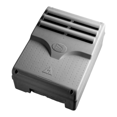
HAWE Hydraulik PLVC 16 Series User manual

Programmable logic valve control
type PLVC 16
D 7845
Programmable logic
valve control
February 2006-00
HAWE HYDRAULIK SE
STREITFELDSTR. 25 • 81673 MÜNCHEN
5
© 2000 by HAWE Hydraulik
1. General information
Extension module with
-Receiver unit of the radio control (optional)
-Additional inputs/outputs
Basic module with
-Interfaces for CAN-Bus, RS232
-Inputs/Outputs
-Hardware Emergency-Stop loop
Diagnosis display
Antenna socket
for radio control
(optional)
See also other electronic valve controls/accessory:
Type PLVC 2 acc. to D 7845-2
Type PLVC 4 acc. to D 7845-4
Type PLVC-CAN acc. to D 7845-Z
The programmable logic valve control of type PLVC 16 consists of a complex PLC-enabled micro-control unit with integrated
amplifiers for mobile and stationary hydraulic applications.
The wide range of possible applications includes, among others:
'Cranes, crane systems
'Construction machines
'Complex hoisting equipment
'Logging equipment
'Hydraulic clamping systems for machine tools
'Presses
The various control tasks are realized through:
'A modular system with extension and supplementary modules
-Basic module
-Extension module (additional inputs/outputs, receiver for radio control) (optional)
- Text display for diagnosis, and parameterization (via CAN-Bus)
-Large display for diagnosis, and parameterization (via CAN-Bus)
-CAN-Bus controlled power relay
'Flexible programmability according to IEC 61131-3 standard (PLC-programming via instruction list (IL), function block diagram
(FBD) or structured text (ST))
'Various interfaces (RS232, CAN-Bus)
'Free parameterization of all outputs, as well as complete diagnosis capability and short-circuit protection
'Remote diagnosis via modem or mobile phone
'Combination of multiple PLVC’s via CAN-Bus within one integrated unit for the control of complex systems
All relevant standards regarding personal safety, EMC, vibration- and shock-proofness are complied with.
The main performance parameters include furthermore:
(the values in brackets specify the performance range of the basic module)
'Input
-Max. 24 (8) digital inputs (for limit switches, pressure switches, push buttons, etc.)
-Max. 24 (8) analog inputs (for joysticks, potentiometers, sensors such as analog pressure sensors)
-Emergency-Stop signal (opto-decoupled)
-4 (1) frequency inputs (for indexing switches, rev. counter, incremental encoder, etc.)
-Optionally integrated radio control module (receiver) incl. Emergency-Stop lock
-Power supply 10 ... 30 VDC, max. 16 A
'Output
-Max. 32 (16) outputs for prop. or ON/OFF valves
-2 analog outputs 0 ... 10 VDC
-Emergency-Stop signal
-2 programmable auxiliary voltage outputs (5, 8, 10, 12 VDC, max. 500 mA, e.g. for potentiometer supply)
-3 Relay outputs
-7- segment display on basic module for error detection
'Functional software features
-PLC programming via IL, FBD or ST
-Parameterization during runtime
-CAN-Bus integrated in the operating system

D 7845 page 2
2. Available versions
2.1 Basic module
Order examples: PLVC 16 - G
PLVC 16 - X - ABC
Basic module Extension module,
see sect. 2.2
General data
Casing, protection class IP 20 acc. to DIN EN 60529 / IEC 60529
Temperature range -40°C to +80°C
Power supply 10 VDC to 30 VDC
Max. total current 16 A
Required external fusing 15 A (slow blow)
Protection Reverse polarity protection
Load dump protection (DIN 40839)
Shock proof (vibration: IEC 68-2-6, shock: IEC 68-2-27)
EMC (EN 50081-1, EN 50081-2, EN 58082-1, EN 58082-2)
Monitoring Short-circuit, undervoltage and overvoltage
Cable break
Cable connections via plug system Phoenix, type MKDS (the connector rails are coded)
Micro controller 80C167, 16 bit
Basic parameter memory EEPROM 256 words
Memory Flash: 256 kByte
RAM: 256 kByte
Accessories Plug set (see sect. 2.3.1)
Software
Diagnosis display (see D 7845 Z)
CAN-Bus power relays (see D 7845 Z)
CAN-Bus display (see D 7845 Z)
Mounting 4 x M4
Casing material Stainless-steel, brushed
Mass (weight) approx. 1.7 kg (basic module)
approx. 0.5 kg (extension module)

D 7845 page 3
Block diagram for basic module
X1
X5
X4
X7
X6
X3
X8
X2
X5
X3
X4
X2
Ubat
Protected
against:
Reverse
polarity, load
dump, under/
over voltage
Emergency-Stop, in
Emergency-Stop, out Emergency-Stop
Emergency-Stop
Monitoring:
Ubat,
temperature,
power on,
system o.k.,
hardware o.k.,
under/over
voltage
Safety relays
UL, CSA, TÜV
Relays 1
Relays 2
Relays 3
3x Relays
out 1 ADC
Monitoring:
Short-circuit,
broken wire,
range
Adjustable power supply 1
5V, 8V, (10 V, 12 V)
max. 500 mA
Adjustable power supply 2
5 V, 8 V, 10 V
max. 500 mA monitoring
Selectable power supply 1 out
Selectable power supply 2 out
Frequency input 1
On-board diagnosis:
1-digit display
Keys: up, down #
8 analog Inputs
0...10 VDC
Range monitoring
8 digital Inputs
0...10 VDC
Voltage monitoring
Words
nominal
actual
Extension module
digital I/O Radio
Control Receiver
Unom
Unom
Uactual
2x Adjustable power supply
Emergency-Stop loop

General data
Supply voltage 10 to 30 VDC
Max. total current 16 A
Required external fusing 15 A (slow blow)
All additional data see sect. 2.1
Mounting with 4 screws onto the basic module
D 7845 page 4
2.2 Extension module
PLVC 16 - X - ABC
PLVC 16 - X - ABCRNBB
Complete set with basic module acc. to sect. 2.1 and
extension module with additional inputs and outputs
Extension with radio control (X14)
Designation extension module
Power specifications of connections
Connector
rail
Function Description Parameters
X1
X2
X3
X4
X5
X6
X7
X8
-Power supply Rated voltage UN10 VDC ... 30 VDC
max. total current (power) 16 A
-Proportional and/or ON/OFF outputs Imin 100 ... 1200 mA
0 - 9 1) Imax 100 ... 2200 mA
(with high-side measuring) Dither frequency 25 ... 200 Hz
Dither amplitude (for PWM) 0 ... 50 %
Cold resistance 2 ... 35 Ohm
-Frequency input Limit frequency flim = 5 kHz
-Prop. and/or ON/OFF outputs 10 - 15 see X2
-Digital inputs 0 - 5 Voltage range 10 ... 30 VDC / 5 kOhm
Debouncing for increasing/
decreasing signal edge can be
activated separately
-Auxiliary voltage 1 and 2 Auxiliary voltage 5, 8, 10, 12 VDC / max. 500 mA
-Emergency-Stop input Opto-decoupled
-Emergency-Stop output Voltage range 10 ... 30 VDC / 6 A
-Relay outputs 1, 2, 3 Voltage 10 ... 30 VDC / 1 A
-Interface CAN-Bus 100, 125, 250 kBaud
-Interface RS232 Interface parameter 19.2 kBaud
-Digital inputs 6, 7 see X3
-Analog inputs 0 - 7 10 bit ADC &1024 steps 4 ... 20 mA
(for joystick, potentiometer 0 ... 10 VDC (default)
Parameterization, see sect. 5.1)
Range monitoring
Parameterization variants:
1)'The outputs 0, 2, 4, 6 etc. can be configured for double solenoids with separate Imin, Imax values, application scenario e.g. to
actuate prop. directional spool valves type PSL / PSV acc. to D 7700 ++, directional spool valves type SWS acc. to D 7951 or
type HSRL acc. to D 7491.
'Simple parameter settings can be used for more efficient circuit functions for ON/OFF solenoids, (parameters, switchover time,
holding current). This may be necessary for reducing the solenoid temperature at 100% ON-time and/or to increase the
switching speed via over-voltage.
'Further parameter settings enable the realization of a fine adjustment range and/or operating with creeping speed at max.
input signal (e.g. with joystick moved to end stop).
Order examples:

D 7845 page 5
X12
X13
RX14
Extension Connector
rail
Function Description Parameters
X10
X11
X
Digital inputs 8 - 23 Voltage range 10 ... 30 VDC / 5 kOhm
Debouncing for increasing/
decreasing signal edge,
can be activated separately
Digital outputs 0 - 7 Imin 100 ... 1200 mA
Safety locked Imax 100 ... 2200 mA
PWM-enabled in 5% steps 1)Cold resistance 2 ... 35 Ohm
Digital outputs 8 - 15
PWM-enabled in 5% steps 1)
Frequency inputs 2, 3, 4 Limit frequency flim = 5 kHz
Analog inputs 8 - 23 see description X 8 (sect. 2.1)
Power supply see description X 1 (sect. 2.1)
Antenna socket for radio control Coaxial connection
Block diagram extension module
X10
X13
X12
X11
X14
Power specifications of connections
1)without high-side measurement
Monitoring:
Short-circuit,
broken wire,
range
Frequency input 2
Frequency input 3
Frequency input 4
Emergency-Stop
Emergency-Stop
Relays 1
16 analog Inputs
0...10 VDC
Range monitoring
16 digital Inputs
10 VDC...30 VDC
Voltage monitoring
From Basic Module
Extension module
digital I/O
Radio Control Receiver
2x Voltage Output
Voltage Output 1
0...10 VDC
Voltage Output 2
0...10 VDC
Voltage Output 1 out
Voltage Output 2 out
Radio ON/OFF
Antenna
Radio - Control
Receiver

D 7845 page 6
3. Software, programming, diagnosis
3.1 Software
The scope of delivery includes the following software package as standard:
-Operating system ("C"-programmed real-time operating system) with integrated CAN-functionality as well as PLC-capability
-Functionality of prop. amplifier for outputs 0-15 (connector rail X2, X3)
-Initializing functions for all inputs and outputs
-Diagnosis software
Available as additional options:
-Diagnosis for CAN-Bus (incl. continuous chart logger)
-Function module, adapted for specified applications (on request)
Examples: -Max. load control
-Synchronicity / Positioning
-Position control (e.g. via option W with prop. directional spool valves type PSL(V) acc. to D 7700 ++)
-Quantity control (e.g. via current regulation valve, types SE and SEH acc. to D 7557/1)
-Pressure control (e.g. via prop. pressure limiting valves type PMV acc. to D 7485/1 and electrical pressure
transducer type DT 1 acc. to D 5440 T and / or type DT 2 acc. to D 5440 T/1)
2.3 Accessories
2.3.1 Plug set
The cable sets are provided for simple completion and start-up of the system
Order coding: Plug set (Basic module) Part No. 6217 2010-00
Plug set (Extension module) Part No. 6217 2100-00
3.2 Programming
3.3 Diagnosis
A distinction has to be made between two different steps of programming:
-Parameterization
Adjusting inputs and outputs to the connected devices
-Process control (PLC-programming)
Evaluation of incoming signals with corresponding actuation of the different outputs (including the initializing of inputs and outputs).
Programming is made with the help of an PLC-software in accordance with IEC 6131-3 using instruction list (IL), function block
diagram (FBD) or structured text (ST).
This way it is possible to quickly get solutions for many applications. More complex applications may require programming in "C".
The RS232-interface is used for loading the software into the valve control's flash memory.
It is possible to set the parameterization during runtime.
The following output equipment can be used for diagnosis:
-PC - connected to interface CAN-Bus (X6) or RS232 (X7), for parameterization, programming, error detection as well as remote
diagnosis via modem. See also description of the "Terminal program" (acc. to B 7845 T)
-7-segment display at the basic module,
for on-site diagnosis (error detection)
-CAN-Bus display (see D 7845 Z),
connected via CAN-Bus, for error detection and adjustment parameterization
3.4 Function blocks
General:
The manufacturer-specific function blocks serve to indicate to the PLC-programmer the interfaces to the actual system. They are
structured into the following two groups.
Group 1: Initializing functions (INI functions)
These functions are used for parameterization and/or configuration of the inputs and outputs - normally only once at
start-up.
It is also possible to apply this parameterization through the operating system. All these parameters and configurations
are included in the system's EEPROM. Thus they are preset and can be overwritten by the PLC-system.
The terminal program (scope of delivery), allows to check , change and save (EPROM and/or file) all settings. Due to
these configurations and parameterizations all data is available at runtime in an already converted and standardized
form, which even can include a ramp or debouncing information. This makes it possible to write the date directly onto the
outputs without conversion and supplemented with ramp information and/or other time-related information.
Group 2: Functions that are normally invoked cyclically during runtime (runtime module)
These functions are used to read input data, logically link them and to write them onto the outputs.
The documentation of the existing function blocks is included in the software package of the PLVC.

D 7845 page 7
4. Dimensions
4.1 Basic and extension module, type PLVC 16
Extension module Basic module 7-segment display
There are three keys below the display
Press left key: error number, unit of ten
Press right key: error number, unit of one
Example: cable break at analog port 17:
No key: capital "A"
Left key: "1" (1x10)
Right key: "7" (7x1)
Center key: Additional errors are displayed if
no additional errors: "0"
It will return to highest priority error, when no is key pressed for 5 sec.
Individual errors:
Merely one flashing point: No error
One dash in center: No radio signal
Two dashes: PLC-error
Three dashes: Emergency-Stop
Upper-case "A": Cable break, analog output
Upper-case "C": CAN-Bus error
Lower-case "c": CAN-Bus warning
Lower-case "d": Undefined level (1.0 ... 3.5 V) at digital input port
Upper-case "F": Radio control error
Upper-case "H": Proportional valve range
Upper-case "P": Proportional valve open
Upper-case "U": Over-voltage
Lower-case "u": Under-voltage
Flash-symbol, downw.: Short-circuit at prop. valve
Flash-symbol, upw.: Short-circuit at digital output or wrong connection
5. Appendix
5.1 Error message of 7-segment display
5.2 Note
The scope of delivery for the programmable logic valve control type PLV includes an operating system and - on special agreement -
a customized software. It is the duty of the customer to test the requested functionality of the PLVC as he is responsible for the
faultless operation and final application of the PLVC.
Attention: Whenever a PLVC is replaced it is additionally necessary to order the current version of the software including the
operation parameter by the manufacturer of the machine.
The customer is responsible to take care that the requested functionality and safety of the application program is fulfilled. When
local laws make an approval by a notified body (testing or approval organization) necessary the customer has to apply for it.

D 7845 page 8
5.3 Installation notes
Electrical connection/ To guarantee the electrical interference protection of the controller, the housing must be connected
Grounding: to GND.
Ground connection has to be carried out on the shortest way between housing and machine and
independent of the minus connection to the module.
Safety instructions: This description is part of the unit. It contains texts and drawings concerning the correct handling of
the controller and must be read before installation or use. Observe the information of the
description. Non-observance of the notes, operation which is not in accordance with use as
prescribed below, wrong installation or handling can result in serious harm concerning the safety of
persons and plant.
The instructions are for authorised persons according to the EMC and low voltage guidelines. The
controllers must be installed and commissioned by a skilled electrician (programmer or service
technician).
The wiring has to comply with the respective standards and has to be galvanically separated from
other circuits. The devices connected at the terminals have to be approved by HAWE Hydraulik
GmbH & Co. KG and the signals fed have to comply with the specifications in this pamphlet. The
device may be used in a temperature range (-40°C to +80°C). Due to the additional self-heating the
housing walls can have high perceptible temperatures when touched in hot environments.
Tampering with the unit can lead to considerable risks for the safety of persons and plant. It is not
permitted and leads to the exclusion of any liability and warranty claims.
Note: Prior to any welding at the machine (vehicle) all PLVC-devices must be diconnected from their
power supply i.e. both terminals (+ and -) respectively a potential separation (electrical isolation) must
be ensured.
This manual suits for next models
1
Table of contents
Other HAWE Hydraulik Control Unit manuals

