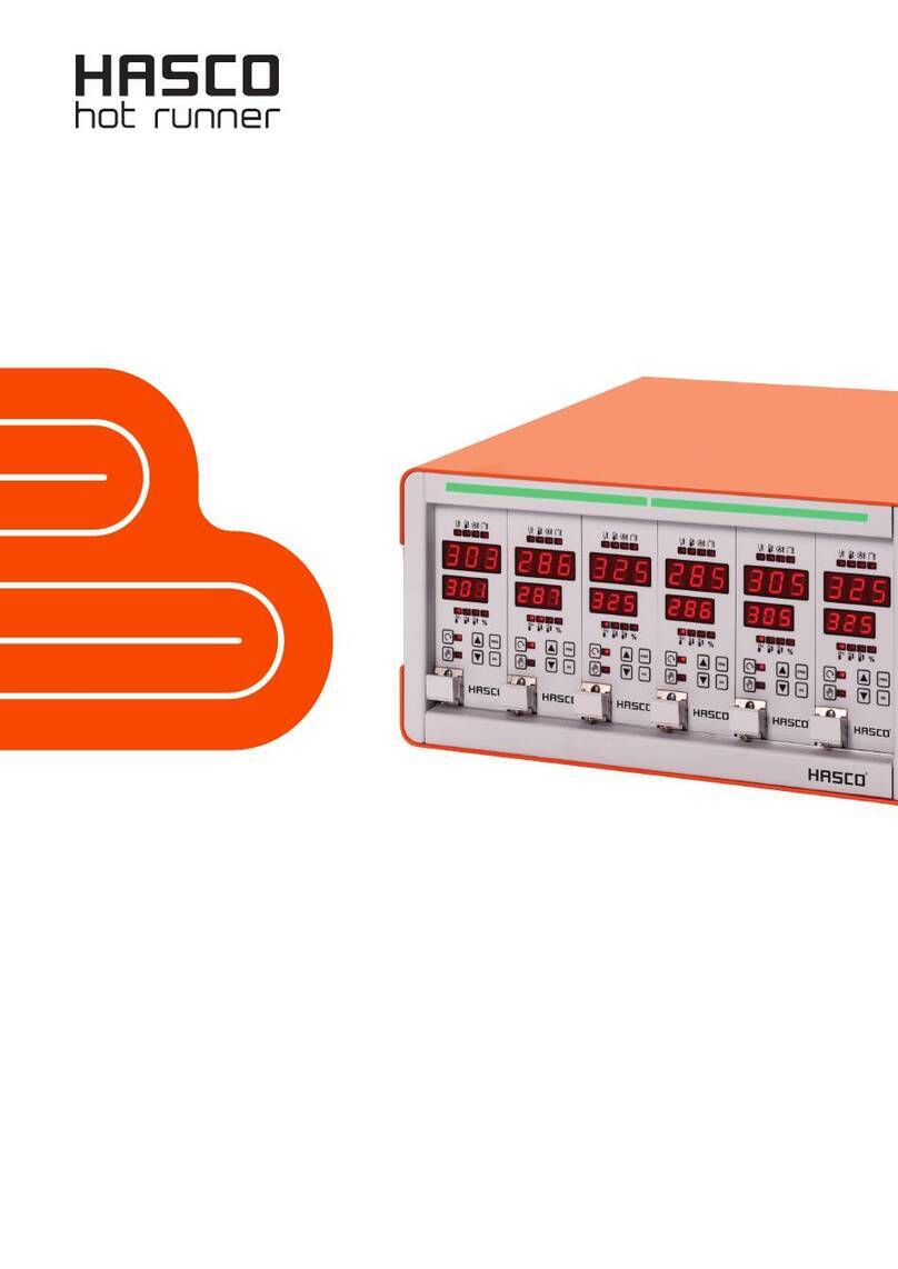
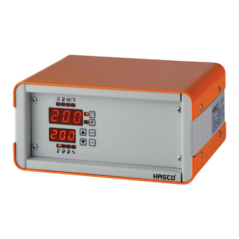
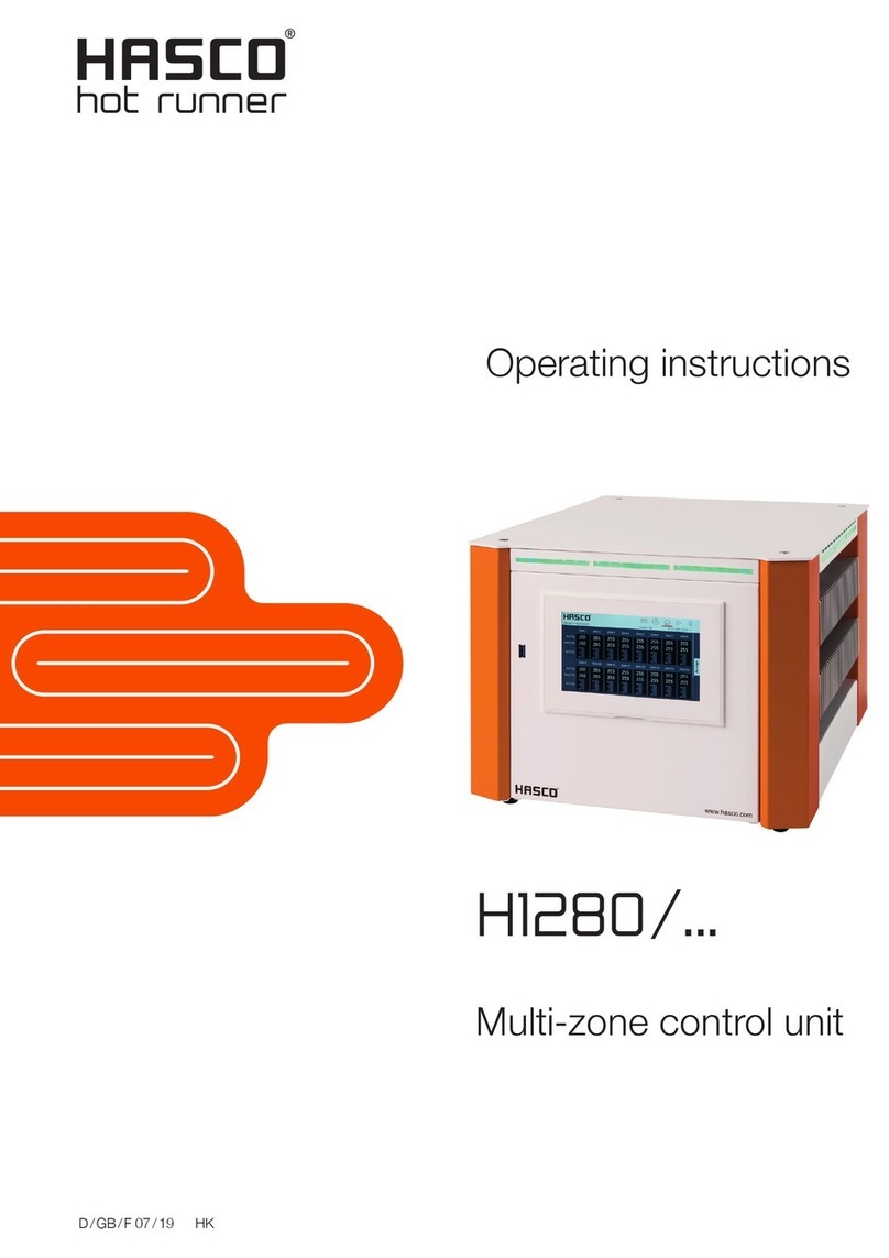
Hasco H1281-6 User manual

GB 05 / 21 HK
Operating instructions
H1281/...
Primezone
Control unit

HASCO hot runner 2
Introduction
Dear customer,
thank you for havin chosen a HASCO temperature controller. This hi h quality device has
been produced in our ISO 9001-certified factory and was shipped to you after a thourou h
quality test.
Unpack Check the device for eventual shippin dama e.
Don't connect dama ed equipment !
Claim the dama e with your shippin a ent.
Read Please read carefully this operatin manual before brin in the device into servi-
ce !
Connect Wirin the device should be done by your qualified electrician followin the in-
structions iven in this manual.
Warranty period is 1 year and includes all malfunctions clearly caused by material, pro-
duction or desi n failures. Repair or replacement in this case are free of char e,
you only pay the shippin cost to our factory. No further claims or requirements
can be accepted, especially for consequential losses or dama es.
Service We help you quickly and at resonable costs. Just send us the device with repair
order and precise description of the malfunction.
Carefull packaging is essential for a safe shipment !
Small repairs up to the maximum amount mentionned in our commercial terms and conditi-
ons are done immediately without formal offer. In any other case, we contact you as soon as
possible to determine the next steps.
To facilitate your orientation in this manual, you find the followin symbols :
Safety advice
Warnin , imminent dan er
General information
Wirin and installation advice

Operations manual H1281
HASCO hot runner 3
Disclaimer
Compliance with the operatin instructions is a prerequisite for the safe operation of the
controller unit and for achievin the specified product and performance characteristics.
HASCO Hasenclever GmbH + Co KG is not liable for personal injury, property dama es or
financial losses that arise from non-compliance with the operatin instructions. Warranty for
defects is excluded in such cases.
This controller unit has been desi ned and built safely by us and also left the plant in a safe
and proper workin condition. To maintain this condition and to ensure safe operation, the
user must follow the instructions and warnin s described in this manual and the safety in-
structions herein included.
Since the observance of safety is outside our sphere of influence, we cannot be held liable
for dama es resultin from failure to comply with one or more of these rules. The list of safety
re ulations can not be complete (mechanical and forei n re ulations). Not mentionin or lis-
tin these rules does not mean that they have no validity.
Commissionin , maintenance and repair work may only be performed by persons which are
reco nized as professionals within the meanin of current le islation (VDE-rules, safety law
for electrical equipment, accident prevention le islation of the employers liabilities insurance
association).
Warranty limitations
The content of this documentation has been carefully established and thourou hly verified.
HASCO Hasenclever GmbH + Co KG assumes no responsibility for any dama e that may
arise from errors in the documentation. In particular, descriptions and technical specifica-
tions are not warranted characteristics in a le al sense.
HASCO Hasenclever GmbH + Co KG has the ri ht to make chan es to the product descri-
bed or documentation without prior notice, if they are made for reasons of reliability and qua-
lity improvements, or by technical pro ress.
We always appreciate any advice for possible errors or potential improvements, that help us
provide you with even better products and services in the future.

HASCO hot runner 4
Table of content
Chapter Pa e
0 Introduction…………………………………………………………….. 2
1 Features.……………………………………………………………….. 5
2 Safety advice…………………………………………………………… 6
2.1 Environmental advice…………………………………………………. 7
2.2 Qualification of personnel…………………………………………….. 7
3 Specification…….……………………………………………………… 9
4 Installation and wirin …...…………………………………………….. 11
5 Operation.………………………………………………………………. 15
5.1 Main switch...…………………………………………………………… 15
5.2 Operatin elements and keys..……………………………………….. 15
5.3 Touchscreen……….…………………………………………………… 16
6 HASCO Touchscreen Operation System...…………………………… 18
6.1 „Homescreen“…………………………………………………………… 18
6.2 Part „Hotrunner“ - view total situation…………………………………. 19
6.2.1 Zones - view in roups. ………………………………………….. 22
6.2.2 Zones - detail view...……………………………………………… 23
6.3 Part „Settin s“………...………………………………………………… 33
6.3.1 Settin s - User…………….………………………………………. 33
6.3.2 Settin s - Lan ua e….…...……………………………………… 36
6.3.3 Settin s - System……..………………………………………….. 37
6.3.4 Settin s - Zones confi uration….....……………………………. 45
6.4 Part „Mould dia nosis“………………….……………………………… 61
6.5 Part „Real time analysis“……………………………………………….. 65
6.6 Part „Mould memory“ ………...………………………………………… 67
6.7 Part „Alarms“………..….……………………………………………….. 71
7 Keyword index……...…………………………………………………… 73
8 CE-conformity certificate……………………………………………….. 76

Operations manual H1281
HASCO hot runner 5
1 Features
Ready to use compact multizone temperature controller for all 230V hotrunner systems
- Compact unit for 6 up to 48 zones
- User friendly touchscreen operation with HASCO ouchscreen Operation
System
- Adaptive control al orithm with automatic self-tunin for every zone
- Safety load-sheddin for process-hi h temperature
- Synchronized heatin for all zones possible
- Boostin for „frozen“ nozzles possible
- Inte rated heater current monitorin
- Intelli ent, pro rammable soft start routine
- Pro rammable alarm settin s for every zone and various self-monitorin
functions
- Standard with mould dia nosis function
- Mould memory and real-time data analysis
- Smartphone- or tablet operation with inte rated WIFI

HASCO hot runner 6
2 Safety advice
1. Please read this advice carefully.
2. Keep this operations manual for use near the machine.
3. This is an electrical device driven with hi h volta e, please respect the current VDE-
and safety re ulations.
Mains volta e and every volta e reater than 42 volts is dan erous !
4. Connect to a power source followin the identification plate on the device.
5. Avoid contamination of the interior with debris, liquids or sprays.
Risk of short-circuit, fire or electric shock !
6. Before cleanin the device, disconnect from the power source.
7. Place the device in a stable manner and prevent it from slippin away. Take care of
the tension load created by the wirin , fix the cables separately from the controller.
8. Clean the surface of the touchscreen only with appropriate, soft cleanin material,
never use solvants or abrasive deter ents or material.
9. Don‘t place the device on hot machine surfaces or near radiation sources of hot
parts.
10. Keep the power connection cable clear of hot parts or sharp ed es.
11. Disconnect the power cable immediately, if
- it was dama ed,
- liquid or parts penetrated the device,
- the device was dama ed by fallin down or other mechanical impacts,
- you have the suspicion of any malfunction.
12. Operation of the device and any other intervention must only carried out by
qualified staff members followin chapter 2.2 .
13. For repair, the device should be send back to our factory. Attempted selfrepair
causes immediate termination of the warranty period !
If spare parts are required, only parts recommended by the supplier must be used.
The use of other parts may cause dama e and/or hazard for operation personnel.
14. Please respect further recommandations and warnin s described in this opera-
tions manual.

Operations manual H1281
HASCO hot runner 7
2.1 Environmental advice
1. This device has been produced accordin to EU-directive 2002/95/EG(RoHS), this
applies also to all of its components.
2. The approved ran e of climatic conditions may not be left durin current operation.
3. The published de ree of protection of the device must be taken into account when
definin the operational and environmental conditions of use.
4. This device must not be used in areas exposed to explosion hazards.
5. Electronic scrap, electronical devices and their components are subject of specific
re ulation concernin treatment of special refuse and may only be disposed by
certified bodies.
2.2 Qualification of personnel
For the use and operation of this device, the followin requirements re ardin
qualification and trainin of the personnel must be taken into account :
1. Operator
2. Tool setter / shift leader
3. Administrator
4. Maintenance and repair personnel
5. Manufacturer
Definition of the different qualification levels see next pa e.
.

HASCO hot runner 8
o 1.) Operator
- Scope of activities :
Startin and stoppin of current operation, readin of actual operational situation and
current alarms, limited alterin of heatin parameters
- Qualification :
Trained for the operation of the actual device and its risks and hazards by a qualified
person, at least of the level „Tool setter / shift leader“
o 2.) ool setter / shift leader
- Scope of activities :
As 1.), additionally alterin of more heatin parameters in the zones confi uration,
loadin and savin of mould data into or from the mould memory, performin of mould
dia nosis pro ram
- Qualification :
Professional trainin or equivalent experience, trained for the operation of the actual
device and its riscs and hazards by a qualified person, at least of the level „Tool set-
ter / shift leader“
“
o 3.) Administrator
- Scope of activities :
As 2.), additionally confi uration of system parameters such such as memory settin s
or interface confi uration, executin of back-ups or software updates in coordination
with the manufacturer of the device
- Qualification :
Professional trainin or equivalent experience, trained for the operation of the actual
device and its riscs and hazards by a qualified person, at least of the level „Adminis-
trator“
o 4.) Maintenance– and repair personnel
- Scope of activities :
As 3.), additionally assembly of cables and wirin harnesses, default findin and repla-
cement of components inside the device while usin ori inal parts
- Qualification :
Electrically skilled person is imperative, trained for the operation of the actual device
and its riscs and hazards by a qualified person, at least of the level „Administrator“
o 5.) Manufacturer
- Scope of activities :
All activities exceedin 4.), especially modifications, up radin of functions and up-
datin of the devices software

Operations manual H1281
HASCO hot runner 9
3 Specification
Mains voltage :
230/240V +/- 10%, 48...63 Hz
Nominal rating/nominal current :
Max. 16A per zone
Up to 8 zones : max. 11 kW / 3 x 16A total
12 to 32 zones : max. 22 kW / 3 x 32A total
40 and 48 zones : max. 22 kW / 3 x 32A total
Fuses :
16A FF, 6,3x32mm, heatin -loads
5A mT, 5x20mm, controller
Standby / alarm-exit :
7-pin plu :
2 floatin contacts (230VAC, max. 3A) for alarms.
One 24V DC input to activate the 2nd (standby-) temperature-value for all zones
simultaneously, wired in parallel with the internal “stand-by” switch.
Safety load-shedding :
Disconnection of all heatin loads in case of process-hi h alarm +50°C, cannot be de-
activated
Heating load alarm :
0,0 ... 19,9A adjustable
Min. 0,4A factory default settin
Sensor inputs :
Thermocouple Fe-CuNi, type J, 0...400°C or 800°C adjustable
Internal zero point correction
Sensor is monitored for cable breaka e, short-circuit and polarity errors.
Thermocouple Ni-CrNi, type K adjustable, internal wirin „K“ on request
ouchscreen
Capacitive 10“ touchscreen with lass surface, non sensitive for dirt or contamination,
shows actual values en setpoints, load current, alarms, confi uration parameters and
mould memory settin s
Power control :
0...100% proportional, zero-volta e switchin
Triac rated up to 35A
Automatic soft-start :
(factory defaults)
Powersettin 50% / temperature 120°C / time 1 min

HASCO hot runner 10
Specification (cont.)
Sensor-/load-connectors :
24-pole standard-industry female plu 16A/400V
Pin assi nment HASCO-norm, other norms available
Accuracy :
0,25% FS
Insulation voltage :
2,5kV mains/sensor circuit
Dimensions :
410 x 367 x 185mm (WxDxH, 6 - 16 zones)
410 x 367 x 345mm (WxDxH, 24 / 32 zones)
410 x 367 x 546mm (WxDxH, 40 / 48 zones)
Additional width of 50mm for heat sink on each side
Colour :
RAL9016 sik loss : Frontpanel and back
RAL9016 structured : other casin parts
RAL2004 structured : Desi n element frontpanel
Weight (depending on number of zones)
H1281-6 : 13,7 k
H1281-8 : 13,8 k
H1281-12 : 15,3 k
H1281-16 : 15,5 k
H1281-24 : 23,9 k
H1281-32 : 25,7 k
H1281-40 : 31,4 k
H1281-48 : 33,2 k

Operations manual H1281
HASCO hot runner 11
4 Installation and wirin
4.1 Installation
The installation site must provide easy access for the operator without hazard. Suffi-
cient mechanical stability must be uaranteed, also secure the device from slippin on
the installation surface.
Protect from heat, radiation and allow free air circulation. Protect power cable from
heat and mechanical stress. Do not place the device on hot surfaces.
Take care of the tension load created by the wirin , fix the cables separately from the
con-troller.
.
4.2 Connection to the power supply
This device must only be operated at the volta e indicated on the name plate.
Please check for a sufficient fuse protection of the CEE power outlet foreseen for the
device. If neutral conductor is not wired properly, dangerous voltages can be created
inside the device.
Protective earth conductor must be provided !
4.3 Connection of heaters and thermocouples
Please compare the connectin dia ram on the temperature controller (backside, near
the outlet) with the dia ram of the mould. Inappropriate connection can destroy con-
troller, heater and TC !
Available mould connectin cables contain heater– and FeCu-Ni compensation wires
for TC. Never use compensation wires to connect a heater.
Maximum load capacity for the heater when using mould connector 24-pol. + PE :
The maximum load capacity of the heater wires (1,5sqmm Cu) depends on the opera-
tin conditions (see also DIN VDE 0298 Part 2 and 4).
@ op. condition : Continuous
@ wire location : Individually, free installation on wall or floor
@ ambiant temperature : 30°C, free air circulation, no heat radiation
VK 24 :
1 heater 12,5 A 2 heaters 12,5 A
3 heaters 11,5 A 4 heaters 10,5 A
5 heaters 10,0 A 6 heaters 9,5 A
Load and C-connection
following HASCO-norm :
Other pin assi nment norms available on request.

HASCO hot runner 12
4.4 Alarm- / Standby-connection
For every zone, three alarm functions can be pro rammed individually. These alarms
operate 2 common floatin contacts as cumulative exits for all zones to ether, they are
wired on a 7-pin connector on the back side. Default settin s are one process-hi h
temperature alarm (A1, pin 2 and 3) as well as one loadbreaka e and leaka e alarm
(A2, pin 4 and 5).
To activate the 2nd temperature set-point (stand-by function), a 24V DC switchin con-
tact is wired to pin 6 and 7. No external power source may be connected to this input.
This function can also be activated manually on the touchscreen.
+24V DC

Operations manual H1281
HASCO hot runner 13
4.5 Casin and functional elements
Front view small casing 6-16 zones :
1 5
2
3
4
1 LED-alarm li htin strip
2 Touchscreen
3 Heatsink (both sides)
4 Fuse holders for load fuses (6 and 8 zones one side, others both sides)
5 USB-data connector
Remark : For the units with 6 and 8 zones, heatsink and fuseholders are only present
on one side of the casin
Back side small casing 6-16 zones :
1
2
3
4
1 Main switch
2 Mould connectors (6 zones each)
3 Alarm connector
4 Power cord

HASCO hot runner 14
Front view high casing 24-32 zones :
Back side high casing 24-32 zones :

Operations manual H1281
HASCO hot runner 15
Front view triple casing 40-48 zones :
Back side triple casing 40-48 zones :

HASCO hot runner 16
5 Operation
5.1 Main switch
Before wirin the device, make sure that the main switch on the back side of the device
is in position OFF „0“. Herewith, all poles are disconnected from the mains volta e. The
main switch can be locked followin EN81-80.
Before workin on the device itself or on a tool connected to it, the switch must be
locked to prevent the device a ainst unintentional restart. This can be done by retrac-
tin the power cable and securin it a ainst re-connectin or by lockin the main
switch with a personal lock.
After havin f inished the wirin completely, switch the device on with main switch in
position „1“(EIN / ON) .
Before start-up of the control software, self-test and enablin of controller operation,
power supply to the heatin elements is locked and cannot be started.
5.2 LED alarm li htin strip
Above the touchscreen on the front panel of the device, a bri ht LED li htin strip is
located for a quick information about the operational state of the system and eventual
alarms.
The LED-strip can constantly show red, yellow or reen li ht, which indicates the follo-
win operational states :
- Red : Alarm is present
- Yellow : Particular operational situation such as softstart, setpoint value not yet
reached or manual powersettin
- Green : Undisturbed operation (see picture above)

Operations manual H1281
HASCO hot runner 17
Safety loadshedding
In addition to both alarms for process-hi h temperature (A1) and heater failure (A2), a
safety loadsheddin function (alarm A0) is wired to the heatin masterswitch of the
system. This functions cuts automatically the total heatin power of the mould, when a
process-hi h temperature in access of 50°C is measured somewhere in the mould. This
settin cannot be switched off, it helps preservin the hotrunner and the mould from
dama es caused by excessive heatin .
In addition to the alarm shown on the touchscreen, the LED alarm lighting strip is illumi-
nated in red.
Before tryin to switch ON a ain the heatin main switch, first check the whole system
and remove the cause of the excess temperature. Before this excess temperature is not
removed, swichin on the heatin a ain is not possible. On the touchscreen, you can
easily find the zone(s), where excess temperature is present.
The alarm limit value A0 can only be altered by an operator with the user ri hts level
„Administrator“.
5.3 Touchscreen
Operation of the controller is made exclusively by the touchscreen. Therefore, a lass
touchscreen with newest technolo y, called „projected capacitive“, is used. In opposi-
tion to older touchscreens (with switchin film on it), this very sensitive technolo y re-
quires only a li ht touch of the screen without any pressure. If there is no reaction of the
system after a li ht touch input, there must be another reason (e. . no ri ht of the user
for this specific function), pressin more firmly on the screen does not chan e the situ-
ation. Operation with loves may be erroneous dependin on the type of love, in
doubt, take the loves out.
You can enlar e the screen ima e with two fin ers as you are used to on actual
smartphones or tablet computers („pinch-to-zoom-function“).
To facilitate readin and operation of the touchscreen, the frontpanel of the device (or
its upper part for the hi her casin types) is tilted.

HASCO hot runner 18
6 HASCO touchscreen operation system
6.1 Homescreen
The “Homescreen” is the start-up operation screen for all functions and pro rams of
the HASCO touchscreen operation system, comparable to the desktop of a PC, smart-
phone or tablet computer. From every screen, the “Home”-button will lead you directly
to the homescreen, this button is always on the upper ri ht corner of the screen.
Back Home
The “Arrow” or “Back”-button will lead you to the last visited screen (this can also be
the homescreen, if you just were there).
On the Homescreen, the 6 main functions of the HASCO touchscreen operation sys-
tem can be selected :
Alarms
Analysis
Mould memory
Hotrunner
Mould diagnosis function
Settings
Operation is the most frequently used function, all actual values and conditions are
shown here. Also, the most common inputs and settin s are done here.
hus, this is the most common screen for current operation of the system.

Operations manual H1281
HASCO hot runner 19
6.2 Hotrunner
This button on the homescreen leads you first to the overview of all zones. Here, the
actual situation of all zones is displayed, which ives you a quick impression of the situ-
ation in the mould. So, we stron ly recommend you to use this screen durin the cur-
rent operation of the controller. All possible situations are shown by different colours,
this permits a quick lance even from reater distance. Zones normally workin within
their defined limits without any alarm are shown in reen, this should be the current
situation durin any operation. In addition to the touchscreen, the actual operational
state of the system is shown by the colour of the LED-alarm li htin strip, see also
chap. 5.2. . Colours on the touchscreen are the same on all menus :
- Green : Undisturbed operation
- Red : Alarm
- Yellow : Particular operation situation : Manual powersettin , measurin zone
or thermocouple linked to another zone
Display actual mould name
Buttons for Buttons Display To le between
common for operational units for operational
functions for display state of state indication
all zones settin s all zones all zones
The display field of the actual mould name is also a button to access directly the mould
memory without passin trou h the homescreen (see chapter 6.6).
Zones overview
Actual mold :

HASCO hot runner 20
In the button array of common functions for all zones, tree functions can be operated :
- Heating ON / OFF :
The heatin of all active zones is bein switched on or off. When switchin on, only
those zones will be switched on, that were active before last switching off.
This function is software based and works only via the touchscreen. If the whole hea-
ting must be switched off into a safe position, e.g. for the wiring to the mould, this must
be done with the main switch on the back side of the unit. This switch is wired to the
main heatin power relay of the system and cannot be influenced by the software.
If the heatin of all zones is de-activated, the presentation of the heatin switch
chan es as follows :
- Boost :
For all zones, the boost-setpoint is activated for a limited period of time. This Boost
holdin time is hold after the boost-setpoint temperature is reached, then, every zone
oes back to the last operation setpoint.
Boost is bein activated for all zones to ether, and if synchronized heatin is active,
also hold until all zones have finished their boost holdin time. Slow zones such as e.g.
manifolds may thus delay the whole boost-process in this case, this may be avoided by
choosing boost parameters accordingly.
- Stand-By :
For all zones, the second setpoint (stand-by temperature) is activated as lon as until
the operator switches it off a ain
Activation of Boost– and Stand-By-function is indicated by oran e colourin of the
respective button, see example in chap.6.2.2 . If one of both functions is active, the
other one is locked.
Alternative :
„Stand-By“ can also be activated with an external switchin contact (see also chapter
4.4).
This manual suits for next models
7
Table of contents
Other Hasco Control Unit manuals
Popular Control Unit manuals by other brands

LOVATO ELECTRIC
LOVATO ELECTRIC ATL DPS1 operating manual

Mitsubishi Electric
Mitsubishi Electric MELSEC Q Series user manual

Kessel
Kessel Comfort Plus SD Instructions for installation, operation and maintenance

pro bel
pro bel V1635V-100 user guide

Advantech
Advantech SOM-6898 user manual
Endress+Hauser
Endress+Hauser RNF22 operating instructions


