Contents
Introduction..............................................................................3
Installation points to remember,
locations for the control box.................................................... 4
Locations for the status LED, making
your wiring connections, reverse polarity
(central door locking).............................................................. 5
Primary harness wire connection guide................................... 6
Wiring diagram........................................................................7
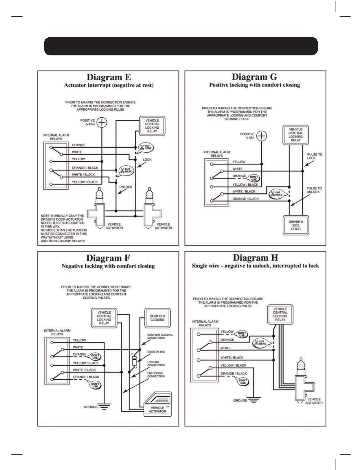
Central locking technical diagrams......................................... 8
3
Congratulations on the purchase of your state of the art HAWK universal upgrade
remote control locking kit. This system has been designed to provide years of
trouble-free operation.
This owner’s guide should help you to get the most out of your system. Please take the
time to read it prior to using the system.
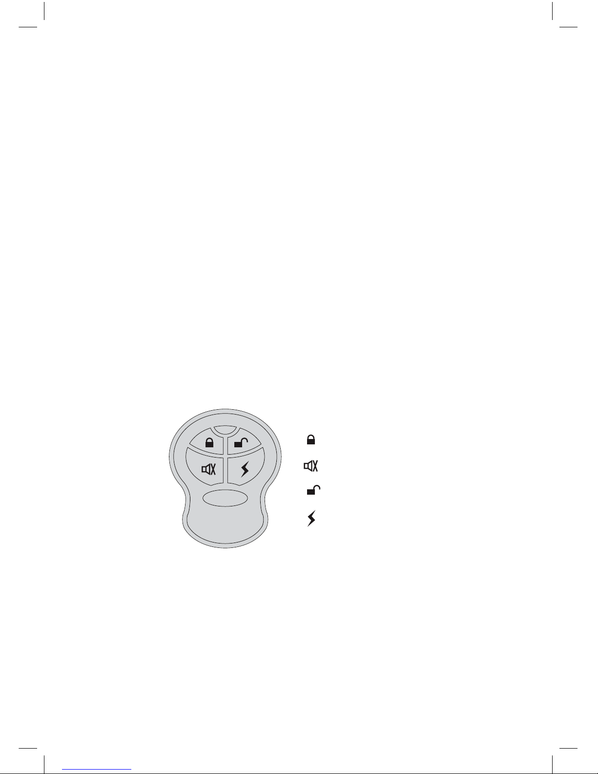
1. To lock doors: press on the remote transmitter once, the doors are locked,
hazard lights will flash once. Windows will close and LED starts to flash.
2. To open doors: press on the remote transmitter once, the doors are unlocked,
hazard lights will flash twice..
3. Remote boot release: press on the remote transmitter for 3 seconds, the boot
is unlocked and hazard lights will flash 3 times. To release boot whilst system is in
unlock mode, press for 3 seconds, hazard lights will flash twice (on
certain models).
4. Car finder: press once hazard lights will flash 3 times. This feature is
particularly useful to find the car in a large car park etc. (on certain models).
HA-008 universal upgrade remote
control locking kit user guide
HAWK
Lock Doors
Boot Release
Unlock Doors
Car Finder
3
Congratulations on the purchase of your state of the art HAWK universal upgrade
remote control locking kit. This system has been designed to provide years of
trouble-free operation.
This owner’s guide should help you to get the most out of your system. Please take the
time to read it prior to using the system.
1. To lock doors: press on the remote transmitter once, the doors are locked,
hazard lights will flash once. Windows will close and LED starts to flash.
2. To open doors: press on the remote transmitter once, the doors are unlocked,
hazard lights will flash twice..
3. Remote boot release: press on the remote transmitter for 3 seconds, the boot
is unlocked and hazard lights will flash 3 times. To release boot whilst system is in
unlock mode, press for 3 seconds, hazard lights will flash twice (on
certain models).
4. Car finder: press once hazard lights will flash 3 times. This feature is
particularly useful to find the car in a large car park etc. (on certain models).
HA-009 PKE universal upgrade remote
control locking kit user guide
HAWK
Lock Doors
Boot Release
Unlock Doors
Car Finder
3
Congratulations on the purchase of your state of the art HAWK universal upgrade
remote control locking kit. This system has been designed to provide years of
trouble-free operation.
This owner’s guide should help you to get the most out of your system. Please take the
time to read it prior to using the system.
1. To lock doors: press on the remote transmitter once, the doors are locked,
hazard lights will flash once. Windows will close and LED starts to flash.
2. To open doors: press on the remote transmitter once, the doors are unlocked,
hazard lights will flash twice..
3. Remote boot release: press on the remote transmitter for 3 seconds, the boot
is unlocked and hazard lights will flash 3 times. To release boot whilst system is in
unlock mode, press for 3 seconds, hazard lights will flash twice (on
certain models).
4. Car finder: press once hazard lights will flash 3 times. This feature is
particularly useful to find the car in a large car park etc. (on certain models).
HA-008 universal upgrade remote
control locking kit user guide
HAWK
Lock Doors
Boot Release
Unlock Doors
Car Finder
3. Two Step Remote Boot release
Step 1. Vehicle is in lock mode Press & Hold on the remote transmitter for
Approx 5 seconds. It will open doors and release the boot.
Step 2. If vehicle is in unlock mode then Press & hold for 3 seconds to release
the boot.
3
Congratulations on the purchase of your state of the art HAWK universal upgrade
remote control locking kit. This system has been designed to provide years of
trouble-free operation.
This owner’s guide should help you to get the most out of your system. Please take the
time to read it prior to using the system.
1. To lock doors: press on the remote transmitter once, the doors are locked,
hazard lights will flash once. Windows will close and LED starts to flash.
2. To open doors: press on the remote transmitter once, the doors are unlocked,
hazard lights will flash twice..
3. Remote boot release: press on the remote transmitter for 3 seconds, the boot
is unlocked and hazard lights will flash 3 times. To release boot whilst system is in
unlock mode, press for 3 seconds, hazard lights will flash twice (on
certain models).
4. Car finder: press once hazard lights will flash 3 times. This feature is
particularly useful to find the car in a large car park etc. (on certain models).
HA-008 universal upgrade remote
control locking kit user guide
HAWK
Lock Doors
Boot Release
Unlock Doors
Car Finder
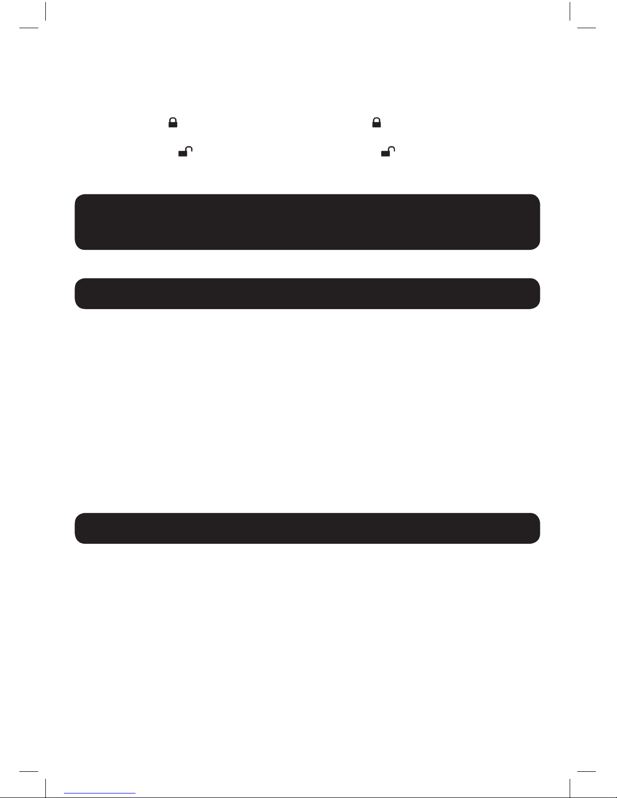
5. Dual Lock and unlock
To have dual locking and unlocking feature enable change JP 2 – to pin number 2-3
on the main PCB (factory default pin number 1-2).
To lock Press on the remote transmitter then press again within 2 seconds for
2nd pulse.
To unlock Press on the remote transmitter then press again within 2 seconds
for 2nd pulse.
3
Congratulations on the purchase of your state of the art HAWK universal upgrade
remote control locking kit. This system has been designed to provide years of
trouble-free operation.
This owner’s guide should help you to get the most out of your system. Please take the
time to read it prior to using the system.
1. To lock doors: press on the remote transmitter once, the doors are locked,
hazard lights will flash once. Windows will close and LED starts to flash.
2. To open doors: press on the remote transmitter once, the doors are unlocked,
hazard lights will flash twice..
3. Remote boot release: press on the remote transmitter for 3 seconds, the boot
is unlocked and hazard lights will flash 3 times. To release boot whilst system is in
unlock mode, press for 3 seconds, hazard lights will flash twice (on
certain models).
4. Car finder: press once hazard lights will flash 3 times. This feature is
particularly useful to find the car in a large car park etc. (on certain models).
HA-008 universal upgrade remote
control locking kit user guide
HAWK
Lock Doors
Boot Release
Unlock Doors
Car Finder
Congratulations on the purchase of your state of the art HAWK universal upgrade
remote control locking kit. This system has been designed to provide years of
trouble-free operation.
This owner’s guide should help you to get the most out of your system. Please take the time
to read it prior to using the system. Visit www.hawkcaralarm.com for update information.
HA-008 universal upgrade remote
control locking kit user guide
HAWK
Lock Doors
Boot Release
Unlock Doors
Car Finder
3
Congratulations on the purchase of your state of the art HAWK universal upgrade
remote control locking kit. This system has been designed to provide years of
trouble-free operation.
This owner’s guide should help you to get the most out of your system. Please take the
time to read it prior to using the system.
1. To lock doors: press on the remote transmitter once, the doors are locked,
hazard lights will flash once. Windows will close and LED starts to flash.
2. To open doors: press on the remote transmitter once, the doors are unlocked,
hazard lights will flash twice..
3. Remote boot release: press on the remote transmitter for 3 seconds, the boot
is unlocked and hazard lights will flash 3 times. To release boot whilst system is in
unlock mode, press for 3 seconds, hazard lights will flash twice (on
certain models).
4. Car finder: press once hazard lights will flash 3 times. This feature is
particularly useful to find the car in a large car park etc. (on certain models).
HA-008 universal upgrade remote
control locking kit user guide
3
Congratulations on the purchase of your state of the art HAWK universal upgrade
remote control locking kit. This system has been designed to provide years of
trouble-free operation.
This owner’s guide should help you to get the most out of your system. Please take the
time to read it prior to using the system.
1. To lock doors: press on the remote transmitter once, the doors are locked,
hazard lights will flash once. Windows will close and LED starts to flash.
2. To open doors: press on the remote transmitter once, the doors are unlocked,
hazard lights will flash twice..
3. Remote boot release: press on the remote transmitter for 3 seconds, the boot
is unlocked and hazard lights will flash 3 times. To release boot whilst system is in
unlock mode, press for 3 seconds, hazard lights will flash twice (on
certain models).
4. Car finder: press once hazard lights will flash 3 times. This feature is
particularly useful to find the car in a large car park etc. (on certain models).
HAWK
Lock Doors
Boot Release
Unlock Doors
Car Finder
3
Congratulations on the purchase of your state of the art HAWK universal upgrade
remote control locking kit. This system has been designed to provide years of
trouble-free operation.
This owner’s guide should help you to get the most out of your system. Please take the
time to read it prior to using the system.
1. To lock doors: press on the remote transmitter once, the doors are locked,
hazard lights will flash once. Windows will close and LED starts to flash.
2. To open doors: press on the remote transmitter once, the doors are unlocked,
hazard lights will flash twice..
3. Remote boot release: press on the remote transmitter for 3 seconds, the boot
is unlocked and hazard lights will flash 3 times. To release boot whilst system is in
unlock mode, press for 3 seconds, hazard lights will flash twice (on
certain models).
4. Car finder: press once hazard lights will flash 3 times. This feature is
particularly useful to find the car in a large car park etc. (on certain models).
HA-008 universal upgrade remote
control locking kit user guide
HAWK
Lock Doors
Boot Release
Unlock Doors
Car Finder
HA-008 universal upgrade remote
control locking kit user guide
HAWK
Lock Doors
Boot Release
Unlock Doors
Car Finder
3
Congratulations on the purchase of your state of the art HAWK universal upgrade
remote control locking kit. This system has been designed to provide years of
trouble-free operation.
This owner’s guide should help you to get the most out of your system. Please take the
time to read it prior to using the system.
1. To lock doors: press on the remote transmitter once, the doors are locked,
hazard lights will flash once. Windows will close and LED starts to flash.
2. To open doors: press on the remote transmitter once, the doors are unlocked,
hazard lights will flash twice..
3. Remote boot release: press on the remote transmitter for 3 seconds, the boot
is unlocked and hazard lights will flash 3 times. To release boot whilst system is in
unlock mode, press for 3 seconds, hazard lights will flash twice (on
certain models).
4. Car finder: press once hazard lights will flash 3 times. This feature is
particularly useful to find the car in a large car park etc. (on certain models).
HA-008 universal upgrade remote
control locking kit user guide
HAWK
Lock Doors
Boot Release
Unlock Doors
Car Finder
Contents
Introduction..............................................................................3
Installation points to remember,
locations for the control box.................................................... 4
Locations for the status LED, making
your wiring connections, reverse polarity
(central door locking).............................................................. 5
Primary harness wire connection guide................................... 6
Wiring diagram........................................................................7
Central locking technical diagrams......................................... 8
3
Congratulations on the purchase of your state of the art HAWK universal upgrade
remote control locking kit. This system has been designed to provide years of
trouble-free operation.
This owner’s guide should help you to get the most out of your system. Please take the
time to read it prior to using the system.
1. To lock doors: press on the remote transmitter once, the doors are locked,
hazard lights will flash once. Windows will close and LED starts to flash.
2. To open doors: press on the remote transmitter once, the doors are unlocked,
hazard lights will flash twice..
3. Remote boot release: press on the remote transmitter for 3 seconds, the boot
is unlocked and hazard lights will flash 3 times. To release boot whilst system is in
unlock mode, press for 3 seconds, hazard lights will flash twice (on
certain models).
4. Car finder: press once hazard lights will flash 3 times. This feature is
particularly useful to find the car in a large car park etc. (on certain models).
HA-008 universal upgrade remote
control locking kit user guide
HAWK
Lock Doors
Boot Release
Unlock Doors
Car Finder
3
Congratulations on the purchase of your state of the art HAWK universal upgrade
remote control locking kit. This system has been designed to provide years of
trouble-free operation.
This owner’s guide should help you to get the most out of your system. Please take the
time to read it prior to using the system.
1. To lock doors: press on the remote transmitter once, the doors are locked,
hazard lights will flash once. Windows will close and LED starts to flash.
2. To open doors: press on the remote transmitter once, the doors are unlocked,
hazard lights will flash twice..
3. Remote boot release: press on the remote transmitter for 3 seconds, the boot
is unlocked and hazard lights will flash 3 times. To release boot whilst system is in
unlock mode, press for 3 seconds, hazard lights will flash twice (on
certain models).
4. Car finder: press once hazard lights will flash 3 times. This feature is
particularly useful to find the car in a large car park etc. (on certain models).
HA-009 PKE universal upgrade remote
control locking kit user guide
HAWK
Lock Doors
Boot Release
Unlock Doors
Car Finder
3
Congratulations on the purchase of your state of the art HAWK universal upgrade
remote control locking kit. This system has been designed to provide years of
trouble-free operation.
This owner’s guide should help you to get the most out of your system. Please take the
time to read it prior to using the system.
1. To lock doors: press on the remote transmitter once, the doors are locked,
hazard lights will flash once. Windows will close and LED starts to flash.
2. To open doors: press on the remote transmitter once, the doors are unlocked,
hazard lights will flash twice..
3. Remote boot release: press on the remote transmitter for 3 seconds, the boot
is unlocked and hazard lights will flash 3 times. To release boot whilst system is in
unlock mode, press for 3 seconds, hazard lights will flash twice (on
certain models).
4. Car finder: press once hazard lights will flash 3 times. This feature is
particularly useful to find the car in a large car park etc. (on certain models).
HA-008 universal upgrade remote
control locking kit user guide
HAWK
Lock Doors
Boot Release
Unlock Doors
Car Finder
3. Two Step Remote Boot release
Step 1. Vehicle is in lock mode Press & Hold on the remote transmitter for
Approx 5 seconds. It will open doors and release the boot.
Step 2. If vehicle is in unlock mode then Press & hold for 3 seconds to release
the boot.
3
Congratulations on the purchase of your state of the art HAWK universal upgrade
remote control locking kit. This system has been designed to provide years of
trouble-free operation.
This owner’s guide should help you to get the most out of your system. Please take the
time to read it prior to using the system.
1. To lock doors: press on the remote transmitter once, the doors are locked,
hazard lights will flash once. Windows will close and LED starts to flash.
2. To open doors: press on the remote transmitter once, the doors are unlocked,
hazard lights will flash twice..
3. Remote boot release: press on the remote transmitter for 3 seconds, the boot
is unlocked and hazard lights will flash 3 times. To release boot whilst system is in
unlock mode, press for 3 seconds, hazard lights will flash twice (on
certain models).
4. Car finder: press once hazard lights will flash 3 times. This feature is
particularly useful to find the car in a large car park etc. (on certain models).
HA-008 universal upgrade remote
control locking kit user guide
HAWK
Lock Doors
Boot Release
Unlock Doors
Car Finder
5. Dual Lock and unlock
To have dual locking and unlocking feature enable change JP 2 – to pin number 2-3
on the main PCB (factory default pin number 1-2).
To lock Press on the remote transmitter then press again within 2 seconds for
2nd pulse.
To unlock Press on the remote transmitter then press again within 2 seconds
for 2nd pulse.
3
Congratulations on the purchase of your state of the art HAWK universal upgrade
remote control locking kit. This system has been designed to provide years of
trouble-free operation.
This owner’s guide should help you to get the most out of your system. Please take the
time to read it prior to using the system.
1. To lock doors: press on the remote transmitter once, the doors are locked,
hazard lights will flash once. Windows will close and LED starts to flash.
2. To open doors: press on the remote transmitter once, the doors are unlocked,
hazard lights will flash twice..
3. Remote boot release: press on the remote transmitter for 3 seconds, the boot
is unlocked and hazard lights will flash 3 times. To release boot whilst system is in
unlock mode, press for 3 seconds, hazard lights will flash twice (on
certain models).
4. Car finder: press once hazard lights will flash 3 times. This feature is
particularly useful to find the car in a large car park etc. (on certain models).
HA-008 universal upgrade remote
control locking kit user guide
HAWK
Lock Doors
Boot Release
Unlock Doors
Car Finder
3. Two Step Remote Boot release
Step 1. Vehicle is in lock mode Press & Hold on the remote transmitter for
Approx 5 seconds. It will open doors and release the boot.
Step 2. If vehicle is in unlock mode then Press & hold for 3 seconds to release
the boot.
3
Congratulations on the purchase of your state of the art HAWK universal upgrade
remote control locking kit. This system has been designed to provide years of
trouble-free operation.
This owner’s guide should help you to get the most out of your system. Please take the
time to read it prior to using the system.
1. To lock doors: press on the remote transmitter once, the doors are locked,
hazard lights will flash once. Windows will close and LED starts to flash.
2. To open doors: press on the remote transmitter once, the doors are unlocked,
hazard lights will flash twice..
3. Remote boot release: press on the remote transmitter for 3 seconds, the boot
is unlocked and hazard lights will flash 3 times. To release boot whilst system is in
unlock mode, press for 3 seconds, hazard lights will flash twice (on
certain models).
4. Car finder: press once hazard lights will flash 3 times. This feature is
particularly useful to find the car in a large car park etc. (on certain models).
HA-008 universal upgrade remote
control locking kit user guide
HAWK
Lock Doors
Boot Release
Unlock Doors
Car Finder
Take the Remote Fob with you and walk away from the vehicle up to approx 2-3 metre,
the doors are locked automatically. The turn indicator lights will ash once to conrm
the doors been locked. The LED indicator will ash.
Approach your vehicle within a range of approx 1 metre, the system automatically
identify you with a valid remote fob and unlock doors immediately. The turn indicator
will ash 2 twice to conrm the doors have been unlocked.
NOTE: LED indicator on remote fob will ash continuously within radio range of the system.
Passively LOCK doors
Passively UNLOCK doors
Manually Open / Close Doors