manuals.online logo
Brands
  1. Home
  2. •
  3. Brands
  4. •
  5. Transient Modules
  6. •
  7. Control Unit
  8. •
  9. Transient Modules 1F User manual

Transient Modules 1F User manual

1F DIY build manual - Version 2.0
Hello!
This guide is for building the 1F module from Transient Modules.
It is good to have basic soldering skills and to be able to identify electronic components
before starting this kit. In case you're an experienced DIYer, please read all the steps
thoroughly before starting as some of them are not so obvious.
The 1F kit consists of two boards and all the parts comes in only two bags separated.
See the parts list below to identify each one of them easily before start building:
Part Qty Part Qty Part Qty
Resistors: Ics: Transistors:
Resistor 100K 0.1% 5 DG409DJ 1 2N3904 2
Resistor 100K 1% 1 TL074/084 1
Resistor 10K 1% 1 Regulator:
Resistor 1K 1% 1 Sockets: 3.3V 1
Resistor 4K7 1% 1 14 pin DIP 1
Resistor 100R 1% 1 16 pin DIP 1 Spacers:
Jack mono 4 11mm 1
Capacitors:
100nF 4 Screws:Others:
22pF 2 M3 silver screw 2 LEDs 1
10uF electrolytic 2 M3 black screw 2 Knurled nuts 4
Ferrite bead 2
Diodes: Headers: Mini switch 2
1N4007 2 5 pin header female 2 Panel 1
5 pin header male 2 Bottom PCB 1
Potentiometers: Power connector 1 Top PCB 1
100KB 1 Ribbon Cable 1
ʕ•ᴥ•ʔ
1F DIY build manual - Version 2.0
1. Let's begin with the back PCB. Start by
emptying the bag into a bowl or container.
This makes it easier to pick parts as you
need them and you’re a lot less likely to lose
anything.
2. Solder the two ferrite beads.
3. Solder the two 1N4007 diodes.
NOTE! The gray ring on the diode should match
the silkscreen on the PCB.
4. Solder the 3x 100nF capacitors (104).
5. Solder the 2x 22pF capacitors (220).
6. Solder the two 10uF electrolytic capacitors
(labelled 10uF).
NOTE! The longer leg should be positioned in
the pad marked with the positive symbol.
!"# $%&'()#*+(#,-(#.//0#10.1% tolerance2#
)(343*%)3"#5+(67)(#&8)9()#*+8:#*+(#3;8<(#%:#
*+(#=%8)'"#>&8<(#*+(?#3*8:'4:9#@;A#83#
3+%B:"
8. Solder the IC Sockets. C8D(#3@)(#*+(#
:%*<+(3 4:#*+(#3%<D(*3#?8*<+#*+(#34&D3<)((:.
9. T8D(#*+(#5E/FG#8:'#*+(#HIG/J#8:'#;&8<(
*+(?#4:#*+(#3%<D(*3#B4*+#*+(#:%*<+#%:#*+(#
*%;#K8<(#8*#*+(#38?(#(:'#83#*+(#:%*<+#4:#*+(#
3%<D(*#8:'#34&D3<)((:"#
1F DIY build manual - Version 2.0
10. Solder the power header.
11. Place the two 5 pin male header and
solder both ensuring they are 90º to the
PCB. Back PCB is now finished!
12. Top PCB! Solder the 5x resistors. Double
check before soldering (use multimeter if
possible), the color codes are very similar
between them:
100K: brown, black, black, orange, brown.
100R: brown, black, black, black, brown.
10K: brown, black, black, red, brown.
1K: brown, black, black, brown, brown.
4K7: yellow, violet, black, brown, brown.
13. Solder the two 2N3904 transistors T1
and T2, and the 100nF capacitor (labelled
104).
.G"#$%&'()#*+(#L"LM#)(9@&8*%)A#&8=(&&('#
KY5033"
15. Solder the two 5 pin female header.
NOTE! This part is placed at the bottom of the
PCB and soldered from the top, as shown.
16. Screw the 11mm spacer using a M3
black screw. Place the 100KB potentiometer,
the 4x jack sockets, the LED and the 2x
toggle switches (leave one hex nut on the
bottom of both switches).
NOTE! The long lead of the LED should be
positioned in the pad marked with the positive
symbol.
- DO NOT SOLDER ANYTHING YET -
1F DIY build manual - Version 2.0
17. Place the front panel. Screw the 4 jack
knurled nuts and the 2 toggle switches with
the remaining hexagonal nut. Check that the
led is fully inserted through the panel before
soldering and the 'output' nut is centered
with the silkscreen on the panel.
18. Now you can solder all the parts!
19. Join the front PCB and the back PCB
using the pin headers and ensuring the 3mm
hole match the spacer. Screw both boards
with the remaining M3 black screw.
20. Connect the ribbon cable. The red stripe
on the cable must line up with the line
indication on the back of the module.
And...
: ) Module finished! : )
Patch a clock signal into CTRL. The led should
blink following the clock. Set the second switch
at 'Y' and patch the output to an oscillator v/oct
input. The frequency should change depending
on the position of the CV2 pot, only when CTRL
is high. Patch any signal into CV1. The module
should switch between the two signals.
If something is not working as it should, the build process went wrong for any reason
or missed any part, write us to: [email protected]
If everything went fine: congratulations! We hope you had some fun while building the
module, patch wisely and enjoythe 1F !!
2019 · Transient Modules

Other Transient Modules Control Unit manuals

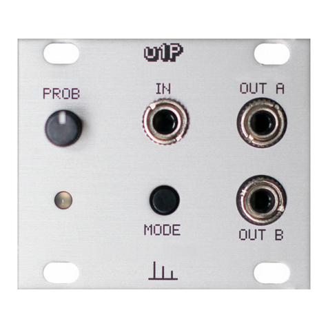
Transient Modules u1P User manual

Transient Modules

Transient Modules u1P User manual

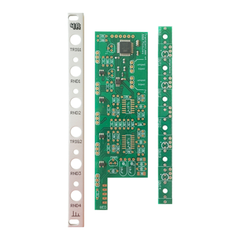
Transient Modules 4R Manual

Transient Modules

Transient Modules 4R Manual

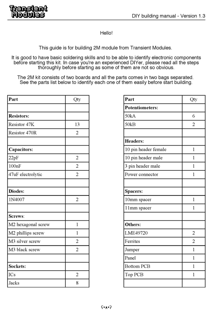
Transient Modules 2M User manual

Transient Modules

Transient Modules 2M User manual

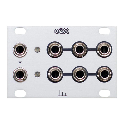
Transient Modules u2X Manual

Transient Modules

Transient Modules u2X Manual

Transient Modules 4R Manual

Transient Modules

Transient Modules 4R Manual

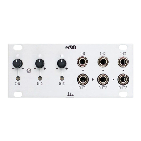
Transient Modules u3A Manual

Transient Modules

Transient Modules u3A Manual

Transient Modules 2M Manual

Transient Modules

Transient Modules 2M Manual

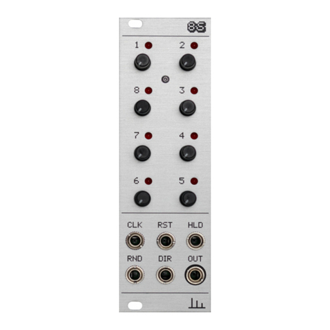
Transient Modules 8S Manual

Transient Modules

Transient Modules 8S Manual

Popular Control Unit manuals by other brands

Zano Controls GRID 1-10V quick start guide

Zano Controls

Zano Controls GRID 1-10V quick start guide

Pfeiffer Vacuum TPG 361 operating instructions

Pfeiffer Vacuum

Pfeiffer Vacuum TPG 361 operating instructions

Sensocon A1 Series Installation and operation manual

Sensocon

Sensocon A1 Series Installation and operation manual

TIS TIS-DMX-48 Manual Installation

TIS

TIS TIS-DMX-48 Manual Installation

Conel CLEAR BOX operating instructions

Conel

Conel CLEAR BOX operating instructions

Penn V46 Series Repair Parts and Service Instructions

Penn

Penn V46 Series Repair Parts and Service Instructions

STIEBEL ELTRON SOKI 7 E plus Operation and installation

STIEBEL ELTRON

STIEBEL ELTRON SOKI 7 E plus Operation and installation

ST Teseo-LIV4F user manual

ST

ST Teseo-LIV4F user manual

Simplex TYCO 4905-9835 quick start guide

Simplex

Simplex TYCO 4905-9835 quick start guide

NI REM-11190 Getting started guide

NI

NI REM-11190 Getting started guide

ProSoft MVI56E-MCMR user manual

ProSoft

ProSoft MVI56E-MCMR user manual

elsner elektronik IMSG 230 compact Technical specifications and installation instructions

elsner elektronik

elsner elektronik IMSG 230 compact Technical specifications and installation instructions

Digi XBee product manual

Digi

Digi XBee product manual

Lutron Electronics GRAFIK 6000 installation instructions

Lutron Electronics

Lutron Electronics GRAFIK 6000 installation instructions

Keysight Technologies 81490A user guide

Keysight Technologies

Keysight Technologies 81490A user guide

Cooper LCMD-10 installation guide

Cooper

Cooper LCMD-10 installation guide

Koganei KFPV050 Series manual

Koganei

Koganei KFPV050 Series manual

Grundfos CIM 2 Series Installation and operating instructions

Grundfos

Grundfos CIM 2 Series Installation and operating instructions

manuals.online logo
manuals.online logoBrands
  • About & Mission
  • Contact us
  • Privacy Policy
  • Terms and Conditions

Copyright 2025 Manuals.Online. All Rights Reserved.