HayssenSandiacre Ultima SV 12-19HR User manual

Certis USA
M334U88011
Panel View 1000
Model: 12-19HR
Rev: 15 Ultima SV
Instruction Manual

.

Introduction
HayssenSandiacre strives to deliver the best packaging technology available combined with
rugged, durable construction to provide a productive and reliable means of packaging product.
To ensure the packaging machine lives up to all expectations, it is important to read and comply
with this instruction manual. Please store this manual near the machine for easy access as it is an
important resource for all personnel involved with the operation and maintenance of the
HayssenSandiacre machine.
This manual provides personnel with the information needed to safely operate and maintain the
HayssenSandiacre machine. It has been designed and written to be used as an instruction tool, as
well as a reference tool, for everyday work. To improve understanding by all levels of users, step-
by-step instructions are provided wherever possible. Important tags mark information about the
best ways to operate the machine. This information can be valuable in maximizing the production
and longevity of the machine. It is important, before operating the machine, that all personnel read
and understand the Safety Chapter. Read all Warning, and Caution notices at the beginning of
each chapter BEFORE attempting to make adjustments or changes. Warning and Caution notices
may also be positioned throughout the manual.
If there are further questions about the operation or maintenance of the machine, please contact
the HayssenSandiacre Service Department.
For ordering additional manuals or replacement parts, please contact the Parts Department. The
Parts Manual and the Instruction Manual include an ordering procedure for assistance when
ordering. To gain the most from the machine, always use genuine HayssenSandiacre parts. Visit
the HayssenSandiacre Internet site (www.HayssenSandiacre.com) for more information
about equipment and parts.
Illustrations may be changed without notice. All dimensions and
specifications are approximate and drawings are not to scale.
Machines are shown without guards for illustration only. Guards
are supplied and must be in place before operation. Sales are
subject to prevailing terms and conditions of sale.
Specifications are subject to change without notice.

Introduction
Copyright ©2002 - 2008 by
HayssenSandiacre, A Barry-Wehmiller Company
ALL RIGHTS RESERVED.
THE REPRODUCTION OR UTILIZATION OF THIS
WORK IN ANY FORM IS FORBIDDEN WITHOUT
THE PERMISSION OF THE PUBLISHER

Page 1
USING THE PARTS MANUAL TO ORDER
REPLACEMENT PARTS
Parts Identification
The part needed may be part of an assembly or an entire assembly. The
Description of each major assembly, located in the Table of Contents
in the Parts Manual, can help identify the specific bill of material
required.
Figure 1: Example of a Bill of Material Page
How to Order
Parts 1. Identify the assembly/part in the Table of Contents which
corresponds with the part needed. (The description helps
identify assemblies.)
2. Turn to the page identified in the Table of Contents to
locate the bill of material for the assembly/part.
3. Note the Line #. for the part ordering.
IMPORTANT:
Do not order parts from the Instruction Manual or Training Man-
ual.
IMPORTANT:
•The major assemblies of the machine make up the Table
of Content for each parts manual.
•Parts that can be ordered are identified by a Line #.
•The Line # corresponds to the number identifying the
part on the assembly drawing.
•The assembly drawing faces the bill of material for the
assembly.
•For assembly drawings referencing multiple bills of
material, refer to the legend on the drawing to identify
specific assembly.

Page 2
Using the Parts Manual to Order Replacement Parts
4. Locate the corresponding number on the drawing to verify
this is the required part.
5.
Figure 2: Assembly Drawing
6. Complete the Parts Request form included in this section
and call or fax the order.
If the part required does not look like the illustration or is not shown in
the Parts Manual, check the original part for a cast or stamped number.
All HayssenSandiacre part numbers have 10 digits.
If a number is not visible, completely describe the part. Draw an illus-
tration with dimensions. Include a photo if possible. Specify left or
right hand when applicable.
Keep the Parts Manual current by adding, changing or deleting bills of
material which represent modifications to the machine.
IMPORTANT:
Numbers such as 1.1 and 1.2, on assembly drawings, indicate that
these parts are part of item number 1.
Key Line #
Assembly
Drawing
Number
If applicable, a legend is
on the drawing for
multiple BOMs

Page 3
These abbreviations are in the Parts Manual.
Contacting
HayssenSandiacre
Abbreviation Meaning
B/M NBR Bill of Material number
REV Revision letter
ASSY NBR Assembly drawing number
ECN Code for HayssenSandiacre use
PARTS BOOK NR Parts book number
ITEM Numerical listing of parts found
on the Bill of Material
DRWG NBR Drawing/Part number
QTY/P UM Quantity per unit of measure
(each, ft. inch, etc...)
SC/SQ Code for HayssenSandiacre use
EMSP Code for HayssenSandiacre use
Address
HayssenSandiacre
Attention: (enter department name or person)
225 Spartangreen Blvd.
Duncan, SC 29334
Telephone
Customer Service [864]
486-4111
After dialing Customer Service, choose from the
following.
Known Extension Press 1
Replacement Parts Press 2
Technical Support Press 3
Field Service Press 4
Training Classes Press 5
Operator Assistance Press 0
Customer Service Fax [864]
486-4222

Page 4
Using the Parts Manual to Order Replacement Parts
Important
Information • List all 10 digits, such as 00000X0000, of the part num-
ber. The sixth digit is always a letter and indicates draw-
ing size.
• Specify method of shipment; truck, RPS, UPS, Air Parcel
Post, Air Freight, etc. HayssenSandiacre®reserves the
right to select the most practical shipping method.
• Machine down, rush and emergency orders are shipped
Air Freight, and an “Emergency Handling” charge may be
added.
• If parts are to be exported, advise HayssenSandiacre about
any special documents the government may require.
• When confirming a telephone order by mail, indicate in
BOLD PRINT that this order confirms the phone order.
Include the date of phone order, and name of the person at
HayssenSandiacre who took the order. HayssenSandiacre
is not responsible for duplicate shipments if the order is
not marked as a confirmation.
• HayssenSandiacre is not responsible and does not issue
credit for parts inappropriately supplied when no machine
serial number has been specified in the parts order.
• HayssenSandiacre reserves the right to substitute vendors.
IMPORTANT:
•Always state Model Number and Serial Number of the
machine. Many machines are built to special customer
specifications. We must have the serial number to
ensure we provide those parts required for the equip-
ment.

Page 5
Requested Parts
Company Information
Date
ShipToInformation
Fax Number
Telephone Number
E-Mail Address
Contact
Machine Serial Number
City State Zip Code
Payment and Approval
Date Required Delivery Date Confirmed
3
Authorizing Signature
Job Title
Purchase Order Number OR Credit Card Number and Expiration Date
Submit Replacement Parts Request Form
(864) 486-4111. When calling, please have
the information requested on the
Replacement Parts Request Formavailable.
Fax the Replacement Parts Request Form
to, (864) 486-4222.
Request Hayssen Replacement Parts online
at http://www.barry-wehmiller.com
4
2
1
Hayssen Part Number Part Name and DescriptionQuantity Customer Part Number
Billing Information
Fax Number
Telephone Number
Contact
Cit y St ate Zip Code
E-Mail Address
Address
Address
Company Name
Company Name
www.
www.barry
barry-
-wehmiller
wehmiller.com
.com
Replacement Parts Request Form
Please print the following information clearly.
R2

Page 6
Using the Parts Manual to Order Replacement Parts

Ultima®SV Instruction Manual Page 1/Rev 15
HAYSSENSANDIACRE®
Table of Contents
Chapter 1: Machine Overview
Component Identification................................................................1-1
Operation Overview .........................................................................1-2
Chapter 2: Safety
Safety Overview ...............................................................................2-1
Safety Signals .........................................................................2-1
Basic Danger and Warning Notices ...............................................2-1
Installation...............................................................................2-1
Guards.....................................................................................2-1
Machine Location....................................................................2-2
Burn, Nip, and Pinch Points ....................................................2-2
Electrical..................................................................................2-3
Replacement Parts..................................................................2-4
Lubrication...............................................................................2-4
Chapter 3: Installation
Machine Delivery..............................................................................3-1
Prepare Site and Utilities for Machine............................................3-1
Installing Air Devices.......................................................................3-1
Installing Electrical Devices............................................................3-2
Ground Fault Circuit Interrupter (GFCI)...................................3-3
Power Source for External Devices.........................................3-3
Remove Protective Coating (optional)...........................................3-3
To Lift Machine from Skid ...............................................................3-4
Product Feed Interface Installation and Operation.......................3-6
Feed System Electrical............................................................3-6
Timing......................................................................................3-6
Product Spacing......................................................................3-6
Mechanical Interface...............................................................3-7
Double Dumping......................................................................3-7
Mezzanine Installation .....................................................................3-8

Page 2/Rev 15 Instruction Manual Ultima®SV
HAYSSENSANDIACRE®
............................................................................................................3-9
Chapter 4: Maintenance
Lubrication Chart .....................................................................4-2
General Maintenance .......................................................................4-2
Rollers......................................................................................4-2
Belts.........................................................................................4-2
Applying LocTite®............................................................................4-2
Rust Colored Stain On Stainless Steel - Causes and Solutions..4-3
Guidelines For Washdown Environments .....................................4-4
Infeed System..........................................................................4-4
Chapter 5: Operator Interface
Allen Bradley PanelView 1000.........................................................5-1
Allen Bradley PanelView 1000 Screens..........................................5-3
Screen Layout..........................................................................5-3
Password Protection......................................................................5-46
How to Enter a Password......................................................5-46
Supervisor Level.........................................................5-46
Engineer Level............................................................5-46
Change Password .................................................................5-47
Password Protection Time Out...................................5-47
Recipe Setup Description..............................................................5-48
Recipe Setup.........................................................................5-48
How to Edit Parameter Values...............................................5-48
Load A Recipe.................................................................................5-49
Test a Recipe ..................................................................................5-50
Saving a Recipe..............................................................................5-50
Double Pull Recipe.........................................................................5-51
Date/Time Setting ...........................................................................5-51
Name Heat Zones ...........................................................................5-52
Upgrading PanelView 1000 Software............................................5-53
Timing Chart - Ultima SV PanelView 1000....................................5-54

Ultima®SV Instruction Manual Page 3/Rev 15
HAYSSENSANDIACRE®
Chapter 6: Unwind Assembly
Unwind Assembly Setup and Operation Procedures...................6-4
Unwind Operation Overview....................................................6-4
Loading a Roll of Film..............................................................6-5
Threading Film ........................................................................6-6
Motorized Unwind Adjustment.................................................6-8
Removing a Depleted Film Roll...............................................6-8
Dancer Roller and Brake Adjustment......................................6-9
Replacing the Bladder in a Pneumatic Spindle...........................6-11
Remove the Bladder..............................................................6-11
Install Bladder........................................................................6-12
Chapter 7: Registration Rollers
Registration Roller Assembly Components..................................7-1
Cleaning..................................................................................7-2
Lubrication...............................................................................7-2
Adjustments.............................................................................7-2
Cantilever Pressure Roller Adjustment .........................................7-3
Top Mounted...........................................................................7-3
Bottom Mounted......................................................................7-3
Advanced Measure, Form, and Pull (MFP) Registration Roller As-
sembly (Optional).............................................................................7-4
With Driven Rollers..................................................................7-5
Style One MFP Rollers............................................................7-5
Style Two MFP Rollers............................................................7-5
Pressure Rollers with Pneumatic Weighting ...........................7-6
USDA Registration Rollers..............................................................7-7
Maintenance .....................................................................................7-7
Pressure Roller Adjustment.....................................................7-7
Cleaning..................................................................................7-7
Lubrication...............................................................................7-7
Miscellaneous Adjustments.....................................................7-7
Advanced Measure, Form, and Pull Registration Roller Assembly
(AMFP) for USDA applications........................................................7-8
Pressure Setting......................................................................7-8
Setting the Pressure on the Fixed Rollers....................7-9
Cleaning................................................................................7-10
Print Registration...........................................................................7-10
Registration Scanner System................................................7-10

Page 4/Rev 15 Instruction Manual Ultima®SV
HAYSSENSANDIACRE®
Registration scanner system components:.................7-11
Scanner Control Unit Components.............................7-12
Registration Mark Sensor Setup............................................7-13
Opaque (non-foil) Material..........................................7-13
Foil Material ................................................................7-13
Transparent Material...................................................7-14
Mechanical Bag Length Setup...............................................7-14
Film with an eyespot (Printed Film).............................7-15
Film without an eyespot (Plain Film)...........................7-15
Motorized Printer Take-Up (Option)..............................................7-16
Chapter 8: Forming Tube Assembly
Former ...............................................................................................8-1
Replacing a Former.................................................................8-1
Last Roller.........................................................................................8-2
Tube...................................................................................................8-2
Forming Tube Maintenance.....................................................8-2
Air Displacement System.........................................................8-3
Sponge Tape...........................................................................8-3
Sponge Tape Maintenance...........................................8-3
Mechanical Tube Stop......................................................................8-3
Mechanical Tube Stop Adjustment..........................................8-3
Pneumatic Tube Stop.......................................................................8-4
Pneumatic Tube Stop Position ................................................8-4
Pneumatic Tube Stop Fine Adjustment...................................8-6
Forming Tube Inserts.......................................................................8-7
Changing Forming Tube Inserts..............................................8-7
Determining FTA Size ......................................................................8-7
FTA Tube / Collar Clearance adjustment .......................................8-7
Quad Seal Forming Tube Assembly (FTA).....................................8-9
Prepare Film Guides and Support Bar.....................................8-9
Side Plates...............................................................................8-9
Front and Rear Film Plates....................................................8-10
Film Finger Guides (Optional)................................................8-10
Square Forming Tube Assembly (FTA)........................................8-11
Chapter 9: Pull Belt Assembly
Pull Belt Care ....................................................................................9-1

Ultima®SV Instruction Manual Page 5/Rev 15
HAYSSENSANDIACRE®
Clean pull belts........................................................................9-1
Pull Belt Removal and Installation...........................................9-3
Drive Pulley Replacement.......................................................9-3
Pull Belt Pressure Adjustment.................................................9-4
Servo Pull Belt Drive Assembly......................................................9-4
Continuous Motion Pull Belt...........................................................9-5
l................................................................................................9-5
Pull Belt Pressure....................................................................9-5
Pull Belt Centering...................................................................9-6
Pull Belt Alignment..................................................................9-6
Non CMB Pull Belts..........................................................................9-7
Pull Belt Centering Non CMB..................................................9-7
Quad Seal Pull Belts ........................................................................9-8
Restrictor Blocks- Assembly # 03044E0710 Only...................9-9
Pull Belt Tilt ...........................................................................9-10
Side Seal Film Guide Position...............................................9-11
Pull Belt Tension Lever - Assembly # 03044E0710 Only......9-12
Chapter 10: Platen Assembly
Platen Operation ............................................................................10-2
Platen Centering Adjustment.................................................10-2
Platen Distance Adjustment ..................................................10-3
Double Platen Fin Seal Assembly (optional)...............................10-4
Inline Zipper Platen ...............................................................10-5
Changing the Platen...................................................10-5
Four-Side Fin Seal ................................................................10-6
Front Platen Assembly Speed Adjustment............................10-7
Front Platen Centering and Distance Adjustment.................10-7
Rear Platen Centering and Distance Adjustment..................10-9
Quad Seal Platen Assembly........................................................10-10
Platen Actuator Adjustments...............................................10-11
Front Actuator Left/Right Position.............................10-11
Rear Actuator Left/Right Position.............................10-11
Front Actuator In/Out Position..................................10-12
Rear Actuator In/Out Position...................................10-12
Platen Adjustments .............................................................10-12
Side Platen Position/Tilt............................................10-12
Center Platen and Forming Tube Support Bar Position/Tilt
10-13
Center Platen Height................................................10-14

Page 6/Rev 15 Instruction Manual Ultima®SV
HAYSSENSANDIACRE®
Standard Pillow Bag Or Flat Bottom Bag Operation.10-15
Quad Seal to Standard Flat Bottom Bag Operation..10-16
Standard Flat Bottom Bag to Quad Seal Operation..10-16
Quad Seal to Pillow Bag Operation ..........................10-16
Pillow Bag to Quad Seal Operation ..........................10-17
Flat Bottom Bag to Pillow Bag Operation..................10-17
Pillow Bag to Flat Bottom bag Operation..................10-17
Direct Drive Platen with Offset....................................................10-18
Chapter 11: End Seal Assembly
End Seal Operation ........................................................................11-1
Sealing Methods.............................................................................11-3
Resistance.............................................................................11-3
Rotated Jaw Assembly ...............................................11-3
Resistance Sealing Tips .............................................11-3
Quali-Seal..............................................................................11-4
EZseal....................................................................................11-4
Drive Linkage and Shafts...............................................................11-5
Jaw Cleaning...................................................................................11-7
End Seal Adjustments and Procedures .......................................11-7
Replacing Jaw Heaters..........................................................11-7
Remove the Jaw Assembly:........................................11-8
Install the Jaw Assembly With New Heaters:..............11-8
Jaw Closed Proximity Switch Adjustment..............................11-9
Jaw Closed Proximity Switch Verification for Servo Drive
Jaws............................................................................11-9
Pneumatic Jaw Adjustments................................................11-10
Jaw Speed and Cushion...........................................11-10
Replacing and Setting Hydraulic Shock Absorbers ..11-12
Resistance End Seal Adjustments and Procedures .................11-13
Front and Rear Jaw Faces ..................................................11-13
Removal....................................................................11-13
Installation.................................................................11-13
Alignment..................................................................11-13
Testing the Jaw Alignment........................................11-14
Pressure Adjustment.................................................11-14
Adjust Top to Bottom Sealing Pressure....................11-16
Cereal Jaw.....................................................................................11-17
False Header Jaws .......................................................................11-17
ESP End Seal Assembly ..............................................................11-18

Ultima®SV Instruction Manual Page 7/Rev 15
HAYSSENSANDIACRE®
Setup...................................................................................11-18
Quali-Seal Setup- Standard Jaw.................................................11-19
Quali-Seal - ESP Jaw ...................................................................11-28
Carrier Alignment ................................................................11-28
Gripper Alignment ...............................................................11-28
Jaw Face Alignment............................................................11-29
Jaw Pressure Adjustment....................................................11-30
How To Change End Seal Systems............................................11-31
Changing from Quali-Seal to Resistance............................11-31
Changing from Resistance to Quali-Seal............................11-32
Tetra Jaw.......................................................................................11-33
Installation...........................................................................11-34
Setup...................................................................................11-35
Recovery From an E-Stop or Controlled Stop..........11-35
Knife Assembly ............................................................................11-35
Knife Blade Replacement....................................................11-36
Knife Position Adjustment ...................................................11-36
Knife Speed Adjustment......................................................11-37
Linear Plunge Knife (Optional)............................................11-38
Linear Plunge Knife Blade Replacement..................11-38
Linear Plunge Knife Position Adjustment .................11-39
European Designed Perforator Setup.................................11-39
Types of Seal Openability/Failure...............................................11-40
Servo-Driven Jaw Actuator .........................................................11-40
Servo Actuator Jaw......................................................................11-43
Drive Alignment...................................................................11-44
Servo Actuator Drive Jaw Setup .........................................11-49
Drive Belt Replacement.......................................................11-55
Chapter 12: Electrical
Servo ...............................................................................................12-1
Axis Organization...........................................................................12-3
Film Registration ...................................................................12-3
Side Mount Electrical Cabinet.......................................................12-4
.........................................................................................................12-4
Chapter 13: Pneumatics
System Components .....................................................................13-1

Page 8/Rev 15 Instruction Manual Ultima®SV
HAYSSENSANDIACRE®
Filter Regulator with Gauge...................................................13-1
Lubricator....................................................................13-1
Shut-Off and Pressure Relief Valve............................13-2
Air Pressure Switch ...............................................................13-2
Flow Control Valves...............................................................13-2
Slow Start Adjustment - Norgren System..............................13-2
Pressure Switch Setting - Norgren ........................................13-3
Air Valve and Manifold Assembly.................................................13-3
Exhaust Silencer/Separator...................................................13-4
Optional Maintenance Alert and Prevention System (MAPS)13-4
Convert a Dry Air Valve to a Wet Air Valve ..................................13-5
Air System Maintenance................................................................13-6
Filter Regulator......................................................................13-6
Lubricator...............................................................................13-6
Chapter 14: Options
Accu-Track Film Tracking System................................................14-1
Accu-Track Enable ................................................................14-1
Eye Amplifier..........................................................................14-2
Accu-Track System Setup.....................................................14-2
Accu-Track Eye Gap Setup...................................................14-3
Bag Deflator ....................................................................................14-4
Bag Spacer......................................................................................14-5
Bag Spreader ..................................................................................14-6
Width Adjustment...................................................................14-6
Small Bag Squeezer .......................................................................14-7
Bag Squeezer..................................................................................14-7
Bag Thickness Adjustment....................................................14-8
Installation..............................................................................14-8
Bag Support and Eject...................................................................14-9
Assembly Adjustment..........................................................14-10
Ejector Plate Changeover....................................................14-10
Ejector Plate Adjustment .....................................................14-10
Motorized Bag Support and Eject...............................................14-10
Motorized Bag Eject Adjustment Procedure........................14-10
Upper Limit Setting ..............................................................14-11
Lower Limit Setting ..............................................................14-11
Delrin Guide.........................................................................14-12
Slide Chute....................................................................................14-12

Ultima®SV Instruction Manual Page 9/Rev 15
HAYSSENSANDIACRE®
Bag Tucking..................................................................................14-14
Bag Tucking Dimensions.....................................................14-15
Tucker Flat Bottom Bag Option...........................................14-15
Film Splicer...................................................................................14-16
Splicing Film........................................................................14-16
Flat Bottom Bag ...........................................................................14-18
Forming Tube Assembly .....................................................14-18
Corner Creasing Assembly .................................................14-18
Tucking Assembly...............................................................14-19
Setup and Adjustment.........................................................14-20
Movable Bottom Tuckers.....................................................14-22
Bag Support/Eject ...............................................................14-22
K-Seal..................................................................................14-22
Hole Punch Assemblies ..............................................................14-22
Resistance Heated ProPunch.............................................14-22
Heater Position Adjustment......................................14-23
Adjusting Heat Control..............................................14-24
Running Bags Without A Punch...............................14-24
Resistance Round Hole Punch (Mechanical)......................14-24
Hole Punch Alignment..............................................14-25
Hole Size Adjustment...............................................14-25
Sealing Pressure Adjustment ...................................14-26
Punch Rod Removal.................................................14-26
Punch Cylinder Timing .............................................14-26
Running Bags Without A Punch...............................14-27
Rod and Bushing Maintenance ................................14-27
Quali-Seal Round Hole Punch ............................................14-28
Round Hole Punch Setup.........................................14-28
Gripper Pressure Adjustment...................................14-28
Punch Rod Location Adjustment..............................14-29
Heat Control Adjustment ..........................................14-29
Running Bags Without A Punch...............................14-29
Punch Cylinder Timing .............................................14-30
Hole Punch Maintenance .........................................14-30
Motorized Film Unwind................................................................14-30
Web Perforators ...........................................................................14-31
Mechanical Air Relief Roller................................................14-31
Pneumatic Web Punch........................................................14-31
Poker.............................................................................................14-32
Air Cylinder Speed Adjustment ...........................................14-32
Product Stripper (Linkage Operated).........................................14-33
Stripper Bar Gap Adjustment ..............................................14-34

Page 10/Rev 15 Instruction Manual Ultima®SV
HAYSSENSANDIACRE®
Stripper Cylinder Pneumatic Speed Adjustment..................14-34
Stripper Proximity Switch Adjustment..................................14-35
Stripper Linkage Adjustment................................................14-36
Product Stripper (Cam Operated) ...............................................14-37
Stripper Bar Gap Adjustment...............................................14-38
Stripper Cylinder Pneumatic Speed Adjustment..................14-39
Stripper Proximity Switch Adjustment..................................14-39
Mini Product Stripper (Small Bag) ..............................................14-41
Reverse Strip ................................................................................14-41
Pneumatic Printer Backup...........................................................14-42
Setup ...................................................................................14-42
Removing the Backup..........................................................14-43
Shaker Jaw Assembly..................................................................14-43
Adjustments.........................................................................14-44
Removing the Shaker Jaw Assembly .......................14-44
Installing the Shaker Jaw Assembly .........................14-44
Shaker Jaws Speed Adjustment...............................14-44
Shaker Jaw Cylinder Cushion...................................14-44
Shaker Smoothness Tuning......................................14-45
Clamp Release Time ................................................14-45
Proximity Switch Position Adjustment.......................14-45
Stager ............................................................................................14-46
Speed Adjustment ...............................................................14-46
Stager Plate Gap Adjustment..............................................14-47
Linear Stager Cable Replacement.......................................14-48
Static Eliminator ...........................................................................14-51
Components ........................................................................14-51
Static Bar ..................................................................14-51
Cable Supports.........................................................14-52
Power Unit ................................................................14-52
Grounding............................................................................14-53
Machine Frame.........................................................14-53
Power Unit ................................................................14-53
Metal Encased Static Bars........................................14-53
Testing the Power Supply....................................................14-53
Maintenance........................................................................14-54
Troubleshooting Static Bar Problems..................................14-54
Tube Air.........................................................................................14-56
Volumetric Feed System..............................................................14-57
Operation Overview.............................................................14-57
Volumetric Setup .................................................................14-58
Table of contents
Popular Industrial Equipment manuals by other brands

Eaton
Eaton Airflex WCB2 Series ACCOMPANIMENT TO THE INSTALLATION, OPERATION AND MAINTENANCE MANUAL
Nexen
Nexen RB15 user manual
HyQuest Solutions
HyQuest Solutions TB1L instruction manual
Bush Hog
Bush Hog TOUGH CBX48 Operator's manual

SCHUNK
SCHUNK RCE Assembly and operating manual

Seneca
Seneca NTC-150 installation manual
Desoutter
Desoutter Industrial Tools Balancer 12ZG user manual
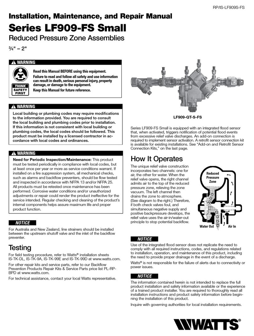
Watts
Watts LF909-FS Installation and repair manual
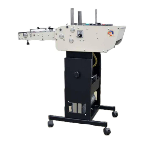
ASTRO
ASTRO AMC-2000 Installation and operating instructions
Valiani
Valiani OMNIA Instruction and maintenance manual
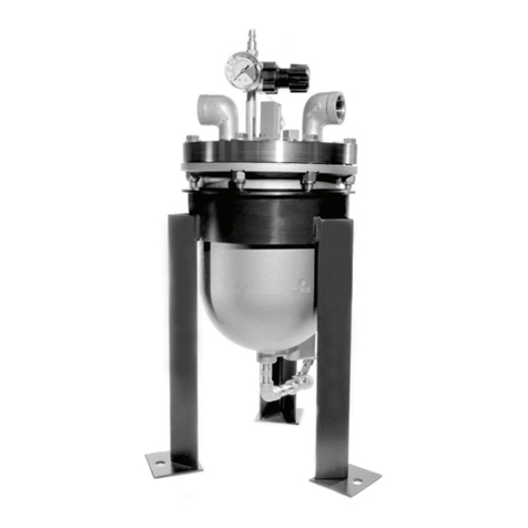
Blacoh
Blacoh SPILLSTOP Installation and operation manual
ABB
ABB A130-M66 Operation manual
