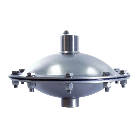
Blacoh SPILLSTOP User manual

When diaphragms fail in AODD pumps, dangerous process uids are expelled from the pump’s air exhaust
putting employees, equipment and the environment at risk. The fully pneumatic SPILLSTOP™ system prevents
the hazardous spill by safely capturing expelled uid and automatically shutting down the failed pump. Optional
warning alarm and backup pump switchover further minimize system downtime for maximum productivity.
Visit www.Blacoh.com for literature online.
Installation and Operation Manual

Copyright © 2021 BLACOH Fluid Controls, Inc. All rights reserved.
Information in this document is subject to change without notice. No part of this publication may be reproduced, stored in a retrieval system or
transmitted in any form or by any means electronic or mechanical, including photocopying and recording for any purpose other than the purchaser’s
personal use without the express written permission of BLACOH Fluid Controls, Inc.
TM
1 BLACOH Fluid Control
MODEL Specications & Installation Information
Model No. Serial No. Installation Date
Body Material / Lid Float Material Pump Area and Number
Purchased From Contact Phone Email
Table of Contents
Safety Warnings ������������������������������������������������������������������������������������������������������������������������������������������������������������2
General Safety ���������������������������������������������������������������������������������������������������������������������������������������������������������������2
ATEX Standard���������������������������������������������������������������������������������������������������������������������������������������������������������������2
Installation & Operation Instructions ��������������������������������������������������������������������������������������������������������������������������3
Shutoff Valves ..........................................................................................................................................3
Installation................................................................................................................................................3
Operation .................................................................................................................................................3
Service .....................................................................................................................................................4
Maintenance.............................................................................................................................................4
Optional Whistle.......................................................................................................................................4
Optional Pressure Switch.........................................................................................................................4
Troubleshooting .......................................................................................................................................5
Figure 1
Typical Installation Diagram .....................................................................................................................6
Figure A
1 Pump Shutoff Valve...............................................................................................................................7
Figure B
1 Pump Shutoff Valve, 1 Exhaust Shutoff Valve.......................................................................................8
Figure C
3 Pump Shutoff Valves.............................................................................................................................9
Figure D
3 Pump Shutoff Valves, 1 Exhaust Shutoff Valve...................................................................................10
Manufacturer’s Limited Warranty & Return Policy���������������������������������������������������������������������������������������������������11

TM
BLACOH Fluid Control 2
Certain models made for the European market are intended for use in potentially explosive atmospheres and meet the
requirements of ATEX directive 2014/34/EU. These models have the AT designation at the end of the part number, comply with
ISO 80079-36, and have an ATEX rating of II 2GD Ex h IIB T4 Gb Db. AT models have a grounding lug and must be grounded
(earthed) before operation.
ATEX Standard
General Safety
ATEX models must be grounded (earthed) before operation�
Always wear safety glasses and other appropriate safety equipment when installing or repairing SPILLSTOP.
Temperature limit is determined by the liquid inside the SPILLSTOP and materials of construction. SPILLSTOP has no moving
parts to generate heat.
DO NOT use SPILLSTOP with incompatible uids. Consult distributor or factory if you are not sure of the compatibility of uids
with SPILLSTOP.
Static spark can cause an explosion resulting in severe injury or death� Ground SPILLSTOP and pumping system
when pumping ammable uids or operating in ammable environments.
WARNINGS Danger of serious injury or death could occur if these warnings are ignored.
CAUTIONS Equipment damage, injury or death could occur if these cautions are not observed.
NOTES Special instructions for safe and satisfactory installation, operation and maintenance.
The following symbols indicate cautions, warnings and notes that must be observed for safe and satisfactory installation, operation and
maintenance.
Safety Warnings
SPILLSTOP should only be installed, operated and repaired by experienced and trained professional mechanics. Read and observe all
instructions and safety warnings in this Manual before installing, operating or repairing.

TM
3 BLACOH Fluid Control
When there is a leak through the pump diaphragm, process uid enters the pump’s air exhaust and is carried to the SPILLSTOP.
As process uid is accumulated in the SPILLSTOP, the internal Float is raised and airow is shifted through the Actuator Valve from
Port 2, the air line connected to the Pump Shutoff Valve, to Port 3 (Figure 1). When this shift occurs, air pressure is removed from the
Pump Shutoff Valve which in turn closes the valve to shut down the pump and prevent the spill. At the same time, the air pressure
shifted to Port 3 of the Actuator Valve is used to pneumatically power the optional Whistle, Power Switch, and/or an additional Pump
Shutoff Valve to automatically start a standby pump.
When the SPILLSTOP triggers a pump shutdown, the most likely cause is a failed pump diaphragm. Excessive moisture laden
compressed air can also cause the SPILLSTOP to trigger a shutdown, simulating a failed pump diaphragm.
Follow the steps below when a pump shutdown occurs:
1. Turn off all air supply to the pump and SPILLSTOP.
2. Drain the contents of the SPILLSTOP into a container appropriate for the process uid being pumped by opening the Drain Valve
on the bottom of the SPILLSTOP. A tube or hose should be attached to the Drain Valve when draining uid.
3. If uid drained from the SPILLSTOP is water condensation only, no further action is necessary. Close the Drain Valve and turn on
the air supply to the pump and SPILLSTOP to restart the pump.
4. If the process uid being pumped is found in the SPILLSTOP, the pump must be repaired immediately to minimize internal damage
and the SPILLSTOP must be serviced.
Operation
1. Install the Pump Shutoff Valve directly to the air inlet of the pump (Figure A). This valve can be installed before or after any
regulator or lubricator installed in the compressed air line. Refer to Figures B-D for appropriate valve locations and air line
connections when installing multiple valves.
The Pump Shutoff Valve must be installed so that air ows into the valve through Port A (or Port 1 depending on
valve design), and exits the valve through Port B (or Port 2) towards the pump�
2. Install an exhaust hose with a pressure rating at least as high as the system air pressure, from the pump’s air discharge port
(exhaust) to the SPILLSTOP Inlet connection port. Alternatively, rigid piping may be used; however, a minimum 6” (15.2 cm) length
of hose should be used for the connection from the pipe to the Inlet connection port.
3. If using an Exhaust Shutoff Valve when there is positive inlet pressure to the pump, install the Exhaust Shutoff Valve in the pump
exhaust line at the SPILLSTOP Inlet connection port (Figures B and D). This valve will close whenever the pump is shut down,
regardless of whether the SPILLSTOP is activated or not.
4. Connect 1/4” plastic tubing from the Pump Shutoff Valve to Port 2 of the SPILLSTOP Actuator Valve (Figure 1).
Since the Pump Shutoff Valve is a normally closed valve, the pump will not operate unless compressed air is supplied
to the Pump Shutoff Valve. Air supplied to the Pump Shutoff Valve must ow through the SPILLSTOP Actuator Valve in
order for the SPILLSTOP to shut down the pump when a leak is detected�
5. Connect an air line with a 1/4” (6.4 mm) female quick connect to the 1/4” (6.4 mm) male quick connect on the SPILLSTOP
Regulator. The quick connect can be removed for hard plumbing.
6. Adjust the Regulator to a minimum of 40 psi (2.7 bar) to start the pump. If the SPILLSTOP is installed with a Whistle and/or more
than two Shutoff Valves, increase pressure to a minimum of 60 psi (4.1 bar).
7. Mounting the SPILLSTOP Stand to the oor or table is not required; however, the Stand includes footpads with holes for this
purpose.
8. The SPILLSTOP is now operational. When compressed air is supplied to the pump, the SPILLSTOP will operate normally. Exhaust
air from the pump will ow into the SPILLSTOP and out of the SPILLSTOP Silencer/Reclassier.
Installation
Depending on the model, SPILLSTOP includes one to four Shutoff Valves. Additional Shutoff Valves are available from Blacoh.
Pump Shutdown: Installed at the pump inlet, the Pump Shutoff Valve automatically shuts down the pump in the event of a diaphragm
failure. A single SPILLSTOP can protect multiple smaller air operated diaphragm pumps (1/2” or 1” models) by routing all of the pump
exhausts through the SPILLSTOP and installing additional Pump Shutoff Valves for each pump. It is possible to do this with larger
pumps but, there could be a signicant reduction in ow due to the restriction added to the pump exhaust.
High Inlet Pressure/Positive Flooded Suction: For applications with positive ooded suction (positive inlet pressure to the pump), it
is recommended to install an additional Shutoff Valve on the pump exhaust line to stop uid in the tank from owing through the failed
diaphragm and out of the pump exhaust when the pump is shut down. For purposes of these instructions, this valve is referred to as an
Exhaust Shutoff Valve.
Shutoff Valves
Installation & Operation Instructions

TM
BLACOH Fluid Control 4
Connected to the tubing installed on Port 3 of the SPILLSTOP Actuator Valve, the pneumatic-to-electric Pressure Switch is used to
power a warning light or other electrical device when the primary pump has failed and SPILLSTOP has shut down the pump (Figure 1).
When SPILLSTOP triggers a pump shutdown, the device connected to the Pressure Switch will be powered on. When the SPILLSTOP
is put back into operation after a pump shutdown, the device will be powered off.
1. The Pressure Switch has three blade-type electrical contact points.
a. Connect the common, usually white wire of the electrical device to the common (COM) blade on the Pressure Switch.
b. Connect the live, usually black wire of the electrical device to the normally open (N.O.) blade connection.
2. Attach the air tube to Port 3 of the Actuator Valve and connect to the Pressure Switch’s barb connection.
Optional Pressure Switch
Connected to the tubing installed on Port 3 of the Actuator Valve, the pneumatic Whistle will sound an auditory alarm alerting personnel
that the primary pump has failed and SPILLSTOP has shut down the pump (Figure 1). When SPILLSTOP triggers a pump shutdown, air
pressure is shifted from Port 2 to Port 3 of the Actuator Valve to pneumatically power the Whistle. The Whistle comes pre-installed from
the factory if ordered with the SPILLSTOP. When ordered separately, the Whistle Kit (part number 50-98K) includes the Whistle, tube
tee and 15 feet of 1/4” tubing. To install the Whistle Kit:
1. Attach the Whistle to the tubing provided and connect to Port 3 of the Actuator Valve. If the SPILLSTOP includes a Pressure
Switch and/or an additional Shutoff Valve for a backup pump, use the tee provided with the Kit to install the Whistle in the tubing
connecting those devices to Port 3. The tee can be inserted at any point in the tubing.
IMPORTANT! The length of tube from the tee to the Whistle must be the same as the length of tube from the tee to the
Pressure Switch and/or the backup pump Shutoff Valve� The Whistle consumes a high volume of compressed air and
if not installed properly, can prevent the Pressure Switch and/or the backup pump Shutoff Valve from activating�
2. Test the Whistle before putting the SPILLSTOP into operation:
a. Connect an air line to the Regulator and adjust the Regulator to a minimum of 40 psi (2.7 bar). If the SPILLSTOP is installed
with more than two Shutoff Valves, increase pressure to a minimum of 60 psi (4.1 bar).
b. Activate the SPILLSTOP by pushing the Float up or raise the Float by turning the SPILLSTOP upside down. Air should start
owing through the tube connected to Port 3 to sound the Whistle and, if installed, the Pressure Switch should activate.
Optional Whistle
The SPILLSTOP is normally maintenance free; however, a function test should be performed at least every 90 days to ensure proper
operation. To perform a function test:
1. Turn off all air supply to the pump and SPILLSTOP.
2. Open the Test Port Plug on the SPILLSTOP lid and ll the SPILLSTOP with approximately 2 cups (.47L) of water.
3. Turn on the air supply to the pump and SPILLSTOP, and adjust the Regulator to a minimum of 40 psi (2.7 bar).
The pump should not operate�
4. Turn off all air supply to the pump and replace the Test Port Plug.
5. Drain the water from the SPILLSTOP into an appropriate container by opening the Drain Valve on the bottom of the SPILLSTOP. A
tube or hose should be attached to the Drain Valve when draining uid.
6. Close the Drain Valve and turn on the air supply to the pump and SPILLSTOP. The pump should operate normally.
Maintenance
The SPILLSTOP must be serviced after every pump shutdown before being put back into operation. To service the SPILLSTOP:
1. Disconnect all air supply to the pump and SPILLSTOP. Remove the SPILLSTOP lid and ush internal areas with water or cleaner
appropriate for the process uid being pumped.
a. Connect an air line to the Regulator and disconnect the plastic tube at Port 2 of the Actuator Valve. Adjust the Regulator to a
minimum of 40 psi (2.7 bar). Air should be owing from Port 2.
b. Activate the SPILLSTOP by pushing the Float up or raise the Float by turning the SPILLSTOP upside down. Air should stop
owing from Port 2.
c. If air does not stop owing from Port 2 when the SPILLSTOP is activated, the Actuator Valve may be clogged or damaged and
should be cleaned or replaced.
2. Reassemble the SPILLSTOP and reconnect the Shutoff Valve(s). Adjust the Regulator to a minimum of 40 psi (2.7 bar) to restart
the pump. If the SPILLSTOP is installed with a Whistle and/or more than two Shutoff Valves, increase pressure to a minimum of 60
psi (4.1 bar).
Service

TM
5 BLACOH Fluid Control
If either the pump or the SPILLSTOP do not operate normally after installation, maintenance or service, follow the steps below in the
order shown to source and x the problem.
1. The SPILLSTOP requires a constant and separate source of compressed air to function properly. With the pump in operation and
air supplied to the SPILLSTOP, adjust the Regulator and verify the gauge reads 40 psi (2.7 bar) or higher.
2. Disconnect all air supply to the pump and SPILLSTOP. Connect an air line to the Regulator and disconnect the plastic tube at
Port 2 of the Actuator Valve. Adjust the Regulator to a minimum of 40 psi (2.7 bar). Air should be owing from Port 2.
a. If air is not owing from Port 2, the Actuator Valve may be clogged or damaged and should be cleaned or replaced.
b. If air is owing from Port 2, check the tubing to the Pump Shutoff Valve to ensure air can ow from the Actuator Valve to the
Shutoff Valve during normal operation.
3. Disconnect the air line to the Regulator. Uninstall the SPILLSTOP completely from the pump and system, and restart the pump.
a. If the pump does not operate normally after removing the SPILLSTOP, refer to the pump manual or contact the pump
manufacturer for instructions to repair the pump.
4. Disconnect all air supply to the pump and reinstall the exhaust hose from the pump’s air discharge port (exhaust) to the
SPILLSTOP Inlet connection port. Do not connect SPILLSTOP Shutoff Valve(s).
a. Check that pump exhaust is entering the SPILLSTOP through the Inlet connection port and exiting through the Test Port Plug.
b. Start the pump to ensure the pump operates normally.
5. Disconnect all air supply to the pump and SPILLSTOP. Remove the SPILLSTOP lid and ush internal areas with water or cleaner
appropriate for the process uid being pumped.
a. Connect an air line to the Regulator and disconnect the plastic tube at Port 2 of the Actuator Valve. Adjust the Regulator to a
minimum of 40 psi (2.7 bar). Air should be owing from Port 2.
b. Activate the SPILLSTOP by pushing the Float up or raise the Float by turning the SPILLSTOP upside down. Air should stop
owing from Port 2.
c. If air does not stop owing from Port 2 when the SPILLSTOP is activated, the Actuator Valve may be clogged or damaged and
should be cleaned or replaced.
6. Reassemble the SPILLSTOP and reconnect Shutoff Valve(s). Adjust the Regulator to a minimum of 40 psi (2.7 bar) to restart the
pump.
a. If the SPILLSTOP is installed with a Whistle and/or more than two Shutoff Valves, increase pressure to a minimum of 60 psi (4.1
bar).
7. Ensure SPILLSTOP Shutoff Valve(s) open when the system is operating.
a. To visually inspect a valve, it is possible to see the piston lift approximately 0.25” from its seat when viewed through Port B.
b. To mechanically inspect a valve, connect a tting to Port A and supply compressed air to that tting. If air escapes Port B, the
valve is open.
8. Disconnect all air supply to the pump and SPILLSTOP and reinstall the Pump Shutoff Valve. Verify that compressed air is supplied
to Port A and that the pump’s air inlet is connected to Port B. Reapply compressed air to the SPILLSTOP to start the pump. If the
pump does not operate normally, the valve may be undersized for the application. Contact Blacoh for assistance.
9. If using an Exhaust Shutoff Valve, disconnect all air supply to the pump and SPILLSTOP and reinstall the valve. Verify that the
pump’s exhaust is connected to Port A and the SPILLSTOP is connected to Port B. Reapply compressed air to the SPILLSTOP
to start the pump. If the pump is not operating normally, the valve may be undersized for the application. Contact Blacoh for
assistance.
Troubleshooting
3. Test the Pressure Switch before putting the SPILLSTOP into operation.
a. Connect an air line to the Regulator and adjust the Regulator to a minimum of 40 psi (2.7 bar). If the SPILLSTOP is installed
with a Whistle and/or more than two Shutoff Valves, increase pressure to a minimum of 60 psi (4.1 bar).
b. Activate the SPILLSTOP by pushing the Float up or raise the Float by turning the SPILLSTOP upside down. Air should start
owing through the tube connected to Port 3 of the Actuator Valve and the Pressure Switch should power on the electrical
device.

TM
BLACOH Fluid Control 6
PORT 2
to Pump Shutoff Valve
ACTUATOR
VALVE
PORT 3
to optional Whistle
and/or Pressure Switch
PORT 1
to Regulator
REGULATOR
GROUNDING
POINT
SILENCER/
RECLASSIFIER
(ATEX Models only)
EXHAUST
SHUTOFF
VALVE
For applications with positive flooded suction (positive inlet
pressure to pump), it is recommended to install an additional Shutoff Valve.
Compressed Air to Pump
Air to open valve
normally closed (N.C.)
Pump Exhaust Air
to SPILLSTOP
Connect to
Pump Exhaust
To optional
Whistle/Switch
WHISTLE
Option
PRESSURE
SWITCH
Option
N.C.
COM
N.O.
TUBING
CONNECTION
PUMP
SHUTOFF
VALVE
PRIMARY
PUMP
Port 2
normally open (no
fluid in SPILLSTOP)
DRAIN
VALVE
Port 3
normally closed
(open when fluid enters
SPILLSTOP)
Figure 1: SPILLSTOP™ Typical Installation
Figure 1
Typical Installation Diagram

TM
7 BLACOH Fluid Control
TUBING
REGULATOR
HOSE
PRESSURE
SWITCH
Option
OUTLET
SPILLSTOP
FROM SHOP AIR
TUBING
INLET
ACTUATOR
VALVE
PUMP EXHAUST AIR
PRIMARY
PUMP
DRAIN
SILENCER/
RECLASSIFIER
WHISTLE
Option
Figure A: SPILLSTOP™ Installation Diagram 1 Pump Shutoff Valve
PUMP SHUTOFF VALVE
COMPRESSED AIR TO PUMP
Figure A
1 Pump Shutoff Valve

TM
BLACOH Fluid Control 8
TUBING
REGULATOR
HOSE
PRESSURE
SWITCH
Option
OUTLET
SPILLSTOP
FROM SHOP AIR
TUBING
INLET
ACTUATOR
VALVE
PUMP EXHAUST AIR
PRIMARY
PUMP
DRAIN
SILENCER/
RECLASSIFIER
WHISTLE
Option
Figure B: SPILLSTOP™ Installation Diagram 1 Pump Shutoff Valve, 1 Exhaust Shutoff Valve
PUMP SHUTOFF VALVE
ELEVATED
TANK
EXHAUST
SHUTOFF VALVE
COMPRESSED AIR TO PUMP
PROCESS FLUID
Figure B
1 Pump Shutoff Valve, 1 Exhaust Shutoff Valve

TM
9 BLACOH Fluid Control
REGULATOR
HOSE
PRESSURE
SWITCH
Option
OUTLET
SPILLSTOP
FROM SHOP AIR
TUBING
INLET
ACTUATOR
VALVE
PUMP EXHAUST AIR
PRIMARY
PUMP
DRAIN
SILENCER/
RECLASSIFIER
WHISTLE
Option
Figure C: SPILLSTOP™ Installation Diagram 3 Pump Shutoff Valves
PUMP SHUTOFF VALVE
COMPRESSED AIR TO PUMP
PUMP SHUTOFF VALVE
PUMP SHUTOFF VALVE
BACKUP
PUMP
ADDITIONAL
PUMP
TUBING
PUMP EXHAUST AIR
HOSE
TUBING
TUBING
Single SPILLSTOP protects multiple pumps with 1 shutoff valve per pump. On larger pumps,
multiple valves could cause reduction in flow due to restriction added to pump exhaust.
Figure C
3 Pump Shutoff Valves

TM
BLACOH Fluid Control 10
REGULATOR
HOSE
PRESSURE
SWITCH
Option
OUTLET
SPILLSTOP
FROM SHOP AIR
TUBING
INLET
ACTUATOR
VALVE
PUMP EXHAUST AIR
PRIMARY
PUMP
DRAIN
SILENCER/
RECLASSIFIER
WHISTLE
Option
Figure D: SPILLSTOP™ Installation Diagram 3 Pump Shutoff Valves, 1 Exhaust Shutoff Valve
PUMP SHUTOFF VALVE
COMPRESSED AIR TO PUMP
PUMP SHUTOFF VALVE
PUMP SHUTOFF VALVE
BACKUP
PUMP
ADDITIONAL
PUMP
TUBING
PUMP EXHAUST AIR
HOSE
TUBING
EXHAUST
SHUTOFF VALVE
ELEVATED
TANK
PROCESS FLUID
TUBING
Single SPILLSTOP protects multiple pumps with 1 shutoff valve per pump. On larger pumps,
multiple valves could cause reduction in flow due to restriction added to pump exhaust.
Figure D
3 Pump Shutoff Valves, 1 Exhaust Shutoff Valve
Other manuals for SPILLSTOP
1
Table of contents
Other Blacoh Industrial Equipment manuals


