HyQuest Solutions TB1L User manual

HyQuest Solutions Pty Ltd
Tipping Bucket Flow Gauge TB1L 100-01 Issue 2:26/9/2016
HYQUEST SOLUTIONS PTY LTD
48-50 Scrivener St, Warwick Farm, NSW 2170,
AUSTRALIA
Phone: +61 2 9601 2022 Fax: +61 2 9602 6971
Email: [email protected]
Web: www.hyquestsolutions.com.au
INSTRUCTION MANUAL
TIPPING BUCKET FLOW GAUGE
MODEL TB1L
QUALITY SYSTEM
ISO
9001
CERTIFIED

HyQuest Solutions Pty Ltd
Tipping Bucket Flow Gauge TB1L 100-02 Issue 1:26/9/2016
TableofContents
I.GENERAL.........................................................................................................................3
II.UNPACKING YOUR TB1L FLOW GAUGE..................................................................3
III.SPECIFICATION...........................................................................................................4
IV.INSTALLATION ...........................................................................................................5
V.TEST OPERATION ..........................................................................................................7
VI.MAINTENANCE...........................................................................................................7
VII.ELECTRICAL................................................................................................................8
IV. APPLICATIONS.............................................................................................................9

HyQuest Solutions Pty Ltd
Tipping Bucket Flow Gauge TB1L 100-03 Issue 1:26/9/2016
TIPPING BUCKET FLOW GAUGE MODEL TB1L
I. GENERAL
The HyQuest Solutions Flow Gauge is used for measuring water flowing out of pipes or
drains. The unit comes with a dual reed switch assembly, thus, when connected to a HyQuest
Solutions data logger, the data can be stored and collected when required. In addition, the
flow gauge can be telemetered by connecting one of the HyQuest Solutions data loggers to a
GSM or Satellite.
Event logging with our Data Logger (Optional)
Telemetry options available on request
Connect to display Counter (Optional)
II. UNPACKING YOUR TB1L FLOW GAUGE
This package should contain:
TB1L Raingauge
Please verify you have received these items and that the Tipping Bucket Flow Gauge
resolution is as ordered.
To prepare the Tipping Bucket Flow gauge for installation:
lift the unit from the carton and place on secure surface
remove the bubble wrap
carefully remove the elastic band/support pad from the bucket.
Your Tipping Bucket Flow gauge is now ready for installation.

HyQuest Solutions Pty Ltd
Tipping Bucket Flow Gauge TB1L 100-04 Issue 1:26/9/2016
III. SPECIFICATION
Receiver: 180mm long x 105mm wide rectangular, PVC UV stabilised.
Sensitivity: one tip at 0.5 litre or 1 litre of water.
Maximum Flow Rate: 25 litres / minute.
Approximate Accuracy: Flow Rate %Error
0.5 litre/min -2%
1.0 litre/min -6%
5.0 litre/min -10%
10.0 litre/min -14%
15.0 litre/min -18%
20.0 litre/min -20%
25.0 litre/min -22%
Humidity: 0 to 95 %
Temperature: - 20 to +70oC
Contact system: dual reed switches potted in soft silicon rubber with varister
protection.
- Max Capacity: 24 Volts (0.5amp max.)
- Resistance: Initial contact resistance 0.1 OHMS
- M.T.B.F: 108to 109Operations
Bucket: PVC UV Stabilised.
Base: Stainless Steel Frame, powder coated grey.
Level: Bulls Eye level adhered to stainless steel base.
Dimensions: Length 390mm, Width 235mm, Height 345mm.

HyQuest Solutions Pty Ltd
Tipping Bucket Flow Gauge TB1L 100-05 Issue 1:26/9/2016
IV. INSTALLATION
The TB1L installation requirements are dependant site conditions. The user needs to ensure
no water is lost outside the area of the collector.
DIAGRAM 1
Water Pipe
Collector
Stop / Adjusting
Screws
Stainless
Steel Base
Reed Switch
Bulls Eye
Level
Shelf or
Bracket
(Optional)
Bucket

HyQuest Solutions Pty Ltd
Tipping Bucket Flow Gauge TB1L 100-06 Issue 1:26/9/2016
Note: Please ensure that the pipe diameter does not exceed the 75mm (2.5”) and is installed
in the centre of the flow gauge as shown in figures above.
DIAGRAM 2
Note: It is advisable to have a vented cover above the collector of the flow gauge to avoid
water loss at high flow rates and in windy conditions.
DIAGRAM 3
Custom made cover with
venting holes. Not supplied
by HyQuest Solutions.

HyQuest Solutions Pty Ltd
Tipping Bucket Flow Gauge TB1L 100-07 Issue 1:26/9/2016
i. Site Selection
Water Flow measurements are intended to be representative of the actual water running out of
the pipe. Some of the more important factors which influence the representativeness of a
gauge are as follows:
Site the gauge on a level surface.
Site should have adequate protection from strong winds.
Water coming out of the pipe should not contain any particles that
could block the collector.
Provide suitable ground surface to avoid splashing into the gauge.
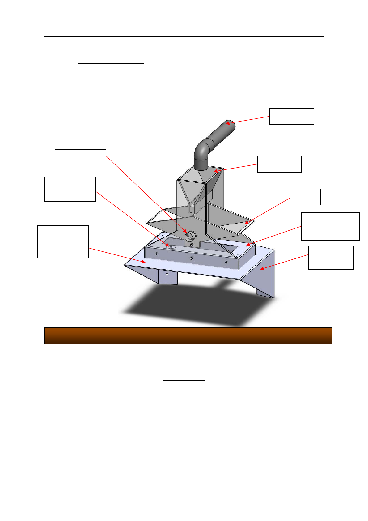
ii. Setting up
Install the gauge on a suitable bracket or shelf, as suggested in
Diagram 1,2 & 3.
The gauge is provided with a level. Proceed to level by ensure the
bracket the gauge is mounted on is level
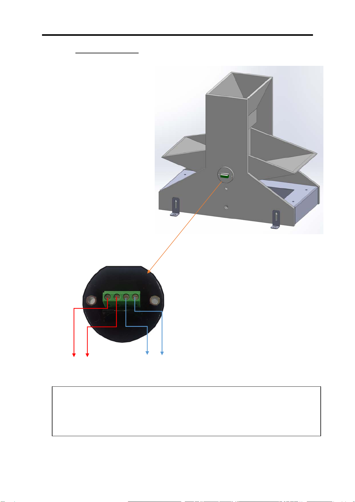
Connect lead to the Flow gauge terminals, in accordance with Diagram
3, and to the recording device, in accordance with manufacturer’s
instruction manual.
V. TEST OPERATION
Manually tip the bucket a number of times, ensuring that each tip is
being recorded and that the tilting mechanism is operating freely.
VI. MAINTENANCE
The only routine maintenance required is cleaning. The following items should be checked
regularly for cleanliness:
Collector area
Interior of bucket
Top surface of adjusting screws
Lubrication of the pivot using (WD40 or equivalent)

HyQuest Solutions Pty Ltd
Tipping Bucket Flow Gauge TB1L 100-08 Issue 1:26/9/2016
VII. ELECTRICAL
Dual reed switches are provided for several reasons:
Two isolated switches permit the control of two separate circuits; e.g. a
local counter and a telemetry circuit.
Parallel connection of both switches increases the current carrying
capacity of the contact system if required.
Parallel switch operation confers a degree of redundancy in locations
where data from the Flow Gauge is critical to flood warning etc.
Note: 2x Digital inputs with maximum capacity of 24 Volts (0.5amp max.). They operate
simultaneously to two different RTU’s (example Data logger & Satellite modem)
DIAGRAM 4
Input 1 Input 2

HyQuest Solutions Pty Ltd
Tipping Bucket Flow Gauge TB1L 100-09 Issue 1:26/9/2016
Input 1 Input 2
IV. APPLICATIONS
Each signal from this reed switch indicates a 0.5L or 1L of water flow depending on
bucket size.
2x Digital inputs with maximum capacity of 24 Volts (0.5amp max.). They operate
simultaneously to two different RTU’s (example Data logger & Satellite)
Table of contents
Other HyQuest Solutions Industrial Equipment manuals