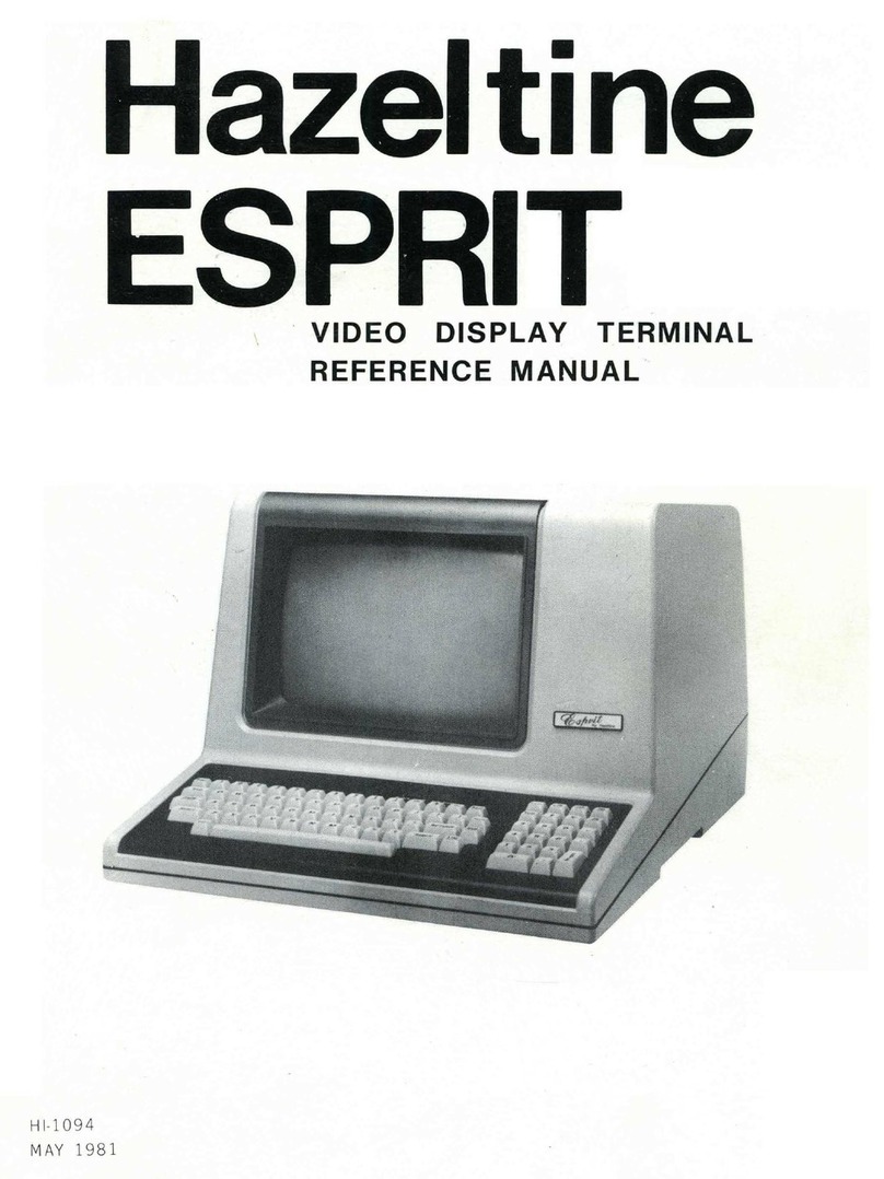
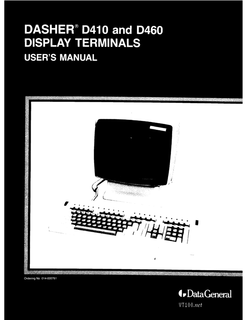
hazeltine 2000 User manual

Operating
Manual
HI 1004A
MARCH 1972
REVISED JANUARY 19 75

This manual is published and distributed by Hazeltine Corporation,
Industrial Products Division. The contents of this manual are sub-
ject to change at any time and without prior notice by Hazeltine. The
information presented herein may not reflect latest changes in the
product. Confirmation and any required clarification of this informa-
tion can be obtained from your local Hazeltine sales representative.
©
CopyrightVO'1972 by Hazeltine Corporation.

Hazeltine
2000Operating
Manual
INTRODUCTION
The Hazeltine 2000 Video Display Terminal is aproduct
of advanced engineering technology which offers the user
greatly enhanced ability to communicate with aremote
computer system.
Speed, silence, and flexibility, coupled with the operator-
oriented features of the Hazeltine 2000 can serve to
greatly improve the efficiency of both software and pro-
grammer in data input/output operations.
With the addition of optional Hazeltine Printer and Tape
Cassette units, increased off-line as well as on-line
capabilities are realized.
This manual will familiarize you with the Hazeltine 2000,
its operation and features. Should you need additional
technical assistance, please contact your Hazeltine Rep-
resentative.
Hazeltine Corporation
Greenlawn, New York 11740
Tel.: (516) 549-8800

CONTENTS
INSTALLATION 1
Set-Up and Connections 1
Turn-On and Warm-Up 1
KEYBOARD AND FRONT PANEL CONTROLS 5
Keyboard 5
Front Panel 9
OPERATION 11
Introduction 11
Operation in Full Duplex 11
Operation in Half Duplex 11
Batch Mode 12
Status Modes 14
APPLICATIONS 16
Introduction 16
Software Control 16
Form Fill-Out Application 17
Setting Up aFormat 18
APPENDIX I. TECHNICAL SUMMARY 21
APPENDIX H. TECHNICAL DESCRIPTION 23
APPENDIX m. CHARACTER CODE CHART 29
APPENDIX IV. CURSOR ADDRESS CHART 30

INSTALLATION
A. SET-UP AND CONNECTIONS
Following unpacking, place units to allow free air circulation
around base and top of unit. Connect cables securely, insuring
that they are free of kinks or tight bends, as follows:
1. Keyboard
Plug the keyboard cable into the marked, corresponding con-
nector in the rear of the display unit. Pin locations and
safety lugs will assure acorrect connection. (Keyboard
cable can be placed under the disolay, if desired.
)
2. Accessory Units
Accessory connectors for optional Tape Cassette, Remote
Monitors and Printer units are marked on the rear of the
display unit near the KEYBOARD CONNECTOR. (See
figure 1.)
3. Data Set or Acoustical Coupler
The standard connector extending from the rear of the display
unit should be plugged into the appropriate data set or coupler
connector.
4. Power Cords
Power cords should be plugged into grounded power outlets.
Do not use adapters which would prevent the display unit
from being properly grounded.
5. Cleaning
Dirt and smudges can be removed from the cabinet with any
number of common household spray cleaners and asoft cloth.
The faceplate should be cleaned only with asoft, damp cloth
or tissue to avoid scratching.
B. TURN-ON AND WARM-UP
Adisplay unit brought in from asignificantly colder environment
should be allowed to sit out of the box for at least one hour prior
to turn -on.

\
DATA CORD DISPLAY UNIT, REAR VIEW
(SERIAL NOS. IOOO TO 10050) N
POWER CORD
DATA CORD DISPLAY UNIT, REAR VIEW
(SERIAL NOS, 12001 AND HIGHER) POWER CORD
POWER CORD
DISPLAY UNIT, PEAR VIEW
(SERIAL NOS. ABOVE 22000)
DATA CORD
Figure 1. Hazeltine 2000 Display Rear View
Turn-On
Set the power ON/OFF pushbutton on the keyboard to ON by de-
pressing itc When power is on, the keyboard pushbutton/
indicator will be lighted. The RECEIVE and LOCAL indicators
on the keyboard will light indicatingthat the Model 2000 is in
Ready mode. Depress reset followed by asimultaneous de-
pression of shift and clear keys. This will reset the logic circuits
to anormal state and clear any extraneous data from the screen.
Allow at least 15 seconds between power "off" and power "on" in
the event of unit power recycling.
k

2. Warm-Up
Allow 30 seconds for display warm-up. At the end of this period,
the cursor will appear in the upper left corner of the display
screen. With the unit in Batch mode, you are able to type charac-
ters on the screen. (See figure 2for location of mode switch In
front panel.
)
a. If the RECEIVE and LOCAL pushbutton/indicators do not
light when the power switch is turned on, press the RESET
pushbutton. If either or both indicators still do not light,
check to see if the cooling fan inside the display unit is in
operation. This can be done by listening for the fan motor
or feeling air movement near the grill in the rear of the dis-
play.
b. If the fan is not operating, turn the power switch off and check
the fuses in the rear of the display (Figure 1). If afuse is
burned out, contact your Hazeltine Representative for are-
placement.
c. If the fan is operating and if after depressing RESET, the
RECEIVE and LOCAL pushbuttons arc not lit, turn the power
switch off and carefully recheck all cable connections. Fol-
lowing this, turn the power switch on again. If after depres-
sing RESET, the RECEIVE and LOCAL pushbutton/indicators
do not light, contact your Hazeltine Representative.
d. If the cursor does not appear after the display CRT has warmed
for areasonable period of time (no more than 3minutes), de-
press the HOME key. This will bring the cursor to the "home"
position in the upper left corner of the display. If the cursor
does not appear and if the entire screen is blank, it is
possible that the CONTRAST control is not adjusted properly
.
To make the adjustment, set the CONTRAST control com-
pletely clockwise. If the cursor still does not appear, turn
the power switch off and contact your Hazeltine Representative.
e. If the Hazeltine 2000 is used infrequently throughout the day,
It is recommended that power be left on rather than continu-
ously turning the unit off and on.

CONTRAST hALf
fULL->
0~>
EVEN
3200
2400 AUTO
Pertains to use at or above
600 baud. Under 600 baud,
switch should be ON.
Selects data transfer speed from
display terminal to computer.
Selects mode of operation (for more de-
tail, see Operation of Hazeltine 2000).
Display intensity can be adjusted for individual
preferences.
Selectable parity check to allow compatibility with those
systems which use parity checking. If you are unsure,
check with your computer system analyst. If parity
checking is not used, set control at one.
Selects EOT (end- of- transmission) code or carriage return to
indicate end- of- message to the remote computer.
Secondary POWER -ON/OFF switch. Place at OFF position to main-
tain control by Keyboard power -ON/OFF pushbutton/indicator.
Figure 2. Hazeltine 2000 Front Panel Controls
i

KEYBOARD AND FRONT PANEL CONTROLS
A. KEYBOARD (Figure 3)
1. TAB
The TAB key automatically moves the cursor to the next tab
stop, if any, whether vertical, horizontal, or diagonal. Tab
stops are set automatically when the display contains both
background and foreground fields. The first foreground char
acter following abackground field is atab stop. If there are
TYPING KEYS
AND
SPACE-BAR
NUMBER CURSOR CONTROLS MODE CONTROL
KEYS AND BUTTONS
KEYS AND INDICATORS
J7|8[9]
§4I[5| 6
11 1 [21[71
»MM1
Figure 3. Hazeltine 2000 Keyboard

no lab stops set, the tab key will cause the cursor to move to
the lower right hand corner of the display. (See discussion
of foreground/background in "operation" section.
2. ESC Escape
Use of this key is optional depending on communication soft-
ware being used. ESC generally is used to generate apro-
gram interrupt signal.
3. CTRL (Control)
The control key is used in conjunction with other character
keys to generate non-printing characters for anumber of
reasons including security, function codes, etc. When CTRL
is used it should be depressed and held while the other required
character key is depressed. CTRL sends special codes by
altering the code pattern of the other key used with it.
4. LF (Line Feed)
The LF key causes the line feed character to be transmitted
when operating in standard full or half duplex mode but has no
other effect. It does not move the cursor down the screen and
does not cause the line feed character to be stored. The line
feed character is stored In BATCH but not executed.
5. CR (Carriage Return)
The CR key moves the cursor back and down to the beginning
of the next lower line thereby accomplishing both carriage
return and line feed.
6. RUBOUT
The RUBOUT key causes acharacter of all "one" bits to be
sent out. Usually rubouts are used as "filler" characters
when program execution delays are required.

7. Number Key Cluster
These keys transmit the same code as the numeric keys across
the top of the keyboard and are provided In an adding machine
cluster to facilitate entry of numeric data.
8. Cursor Control Keys
The HOME key moves the cursor immediately to the home
position (first character position in the top line). The cluster
of four arrow keys are cursor-stepping keys. Each moves
the cursor one space in the indicated direction.
These keys may be pressed in conjunction with the RPT key for
for rapid cursor movement. Cursor positioning with these
keys is completely non-destructive; it will not alter any charac -
ters in the display.
9. Status Mode Indicator/Controls
a. ON/OFF Pushbutton/Indicator
Energizes the display and keyboard units when auxiliary
display Power-ON/OFF switch on front panel is set at OFF.
Lights when power is ON.
b. TRANSMIT Indicator
Lighted when transmit mode is initiated by pressing the
SHIFT and XMIT key or when transmit mode is initiated
by the computer.
c. XMIT Key
Used only during Batch operation. Initiates the batch trans-
mission of atyped entry to the computer by switching the
Model 2000 from the Ready mode or the Local mode to the
Transmit mode. Has no effect during standard half or full

duplex operation. Must be used with the SHIFT key.
d. RECVPushbutton/ Indicator
Lighted whenever the Model 2000 is able to receive, or is
receiving, characters from the computer or from the op-
tional tape cassette unit. Therefore not lighted in any of
the three modes which prevent receiving: Local, Print,
or Transmit (in Batch operation). If pressed while In any
of those modes, this button immediately terminates the
mode and thereby returns the Model 2000 to the Ready mode.
e. PARITY ERROR Pushbutton/Indicator
Illuminates when aparity error has occurred in acharacter,
or characters, as data transferred between computer and
display unit. Depressing the pushbutton will reset the parity
detection circuit and extinguish the light.
f. PRINT Indicator
Lighted when print mode is initiated by depressing the
PRINT key or by the computer.
g. LOCAL Pushbutton/Indicator
Lighted whenever the keyboard is electrically enabled
(unlocked). Therefore not lighted in any of the three
modes which lock the keyboard to prevent garbling by
inadvertent typing: Print, Transmit (in Batch operation),
or Receive (while acharacter is arriving). When pressed,
this button immediately switches the Model 2000 to the
Local mode from any of the other modes.
h. PRINT Key
Initiates abatch readout of the contents of the display to
optional equipment (serial-character hard copies or tape
cassette unit), by switching the Model 2000 from the Ready
mode or the Local mode to the Print mode. Must be used
with the SHIFT key.

i. BREAK Pushbutton/Indicator
Equivalent to the corresponding button on a conventional
teletypewriter terminal. When pressed while the RECEIVE
button is lighted, this button causes abreak signal to be
transmitted to the computer. If the computer is trans-
mitting to the Model 2000 the break signal requests the
computer to cease transmitting and prepare to receive
atransmission from the Model 2000.
j. RESET Pushbutton/Indicator
Interrupts and resets all internal functions while depressed,
and returns the Model 2000 to the Ready mode when re-
leased (or to the Receive mode if incoming characters are
being received). The interrupted functions include synch-
ronization and display refresh, and as aresult, the dis-
play goes completely blank when the RESET button is
pressed and then reappears when the button is released.
The reset button will reset the terminal to the background
input modes.
10. EDIT KEYS
a. CLR/FG -Clears out all data on screen in foreground
(Bright) Intensity.
b. CLEAR -Clears entire screen of data
c. I/C -Inserts character within field
d. D/C -Deletes character from field
e. I/L -Inserts line of data
f. D/L -Deletes line of data
B. FRONT PANEL
1.CR/EOT Pane1Switch
a. Purpose
Selects either the ASCII "Carriage Return" or "End-of-
Transmission" character as the last character transmitted
in Batch mode.

The CR/EOT switch also selects the line turnaround
discipline the Hazeltine 2000 will observe.
(1) In the CR position, the line turnaround will always
be caused by the remote computer via the "super-
visory" channel option of WE202 type modems.
(2) In the EOT position, line turnaround is caused by
the receipt or transmission of the EOT code.
The CR/EOT switch is operational at all speeds select-
able in the terminal.
2. CA ON/CA Auto Panel Switch
a. General -Use of Half Duplex Datasets such as the WE202C
require transmit/receive conditioning by CA which is auto-
matically controlled by line turnaround discipline. Observed
transmit/receive status of the modem is therefore desir-
able for some applications.
b. Terminology
CA -Request to send (from EIA std. RS232 data set con-
nector pin 4).
c. Purpose
With the CA switch set to CA ON, the RECEIVE indicator
reflects the RECEIVE status of the terminal. With the CA
switch set to CA AUTO, the RECEIVE indicator reflects
the status of the modem control signal which in turn controls
the modem transmit/receive status. When the RECEIVE
light is OFF, the modem is conditioned to transmit. When
the RECEIVE light Is ON, the modem Is conditioned to
receive.
d. Intended Use
Normally, for speeds up to 300 baud, type 103 modems
are used and the CA switch should be set to CA ON. For
higher speeds (600, 1200, 1800 baud), a202C-type modem
Is used and switch should be set to CA AUTO.
10

OPERATION
A. INTRODUCTION
There are two basic modes of operation under which the Hazeltine
2000 can be operated: Standard Transmission (switch setting at
HALF or FULL DUPLEX); Batch Transmission (switch setting at
BATCH).
When the unit is operating in either half or full duplex in the
Standard Transmission mode, data which is keyed in is sent
directly to the computer. Each line is terminated with a
carriage return (CR) and any editing or correction that takes
place becomes afunction of the computer program under which
you are operating. Most time shared software recognizes
special characters and has special subroutines for backspacing
and, in some cases, line and character replacement.
In the Batch mode, however, the data that is keyed in is held in
the Hazeltine 2000 memory until the operator chooses to transmit
it to the computer. The operator can prepare one line or several
lines of data and, through use of the cursor control and editing
keys, may make any corrections such as character and line
insertion or deletion, as well as retyping prior to transmission
to the computer system. When the operator is satisfied that
his data is correct and ready for computer input, he depresses
the SHIFT and TRANSMIT keys in addition to or in place of his
last carriage return (CR). The data is then sent to the computer.
B. OPERATION IN FULL DUPLEX
The full duplex mode of communication can only be used when the
communication system is capable of simultaneous two-way trans-
mission. In this mode, data entered from the keyboard is sent
directly to the remote computer system. Upon reaching the com-
puter, the data Is "echoed" back to the Hazeltine 2000 screen.
If modems are used, they must be "Full duplex" type.
C. OPERATION IN HALF DUPLEX
The half duplex mode of communication is used when the communi-
cation system is not capable of simultaneous two-way transmission.
In this mode, the terminal "echoes" all Its own keyed data onto the
screen for the operator to inspect.
11

D. BATCH MODE
The Batch mode may be used with either half or full duplex com-
munciation systems. It is the Batch mode of operation that enables
the operator to take advantage of the editing functions inherent in
the Hazeltine 2000.
1. Preparing Data
Data is entered through the keyboard and displayed on the
screen as it is held in the memory of the Hazeltine 2000.
The operator may wish to enter and transmit one or several
characters, part of aline, afull line, or several lines of data.
In each case the operator has Control of the Keyboard (local
light is lit).
2. Editing Data
The cursor control keys are auseful and important part of the
editing function. The cursor can be moved in any direction on
the screen to position it for acorrection. The cursor keys can
be used with the RPT key for rapid cursor movement.
a. Retyping -To retype acharacter or series of characters,
simply position the cursor at the appropriate starling
point and make the correction. When correction is com-
plete, reposition cursor at transmission point (end-of-
message) or continuation point.
b. Character Insertion -This feature precludes the necessity
of retyping an entire line should acharacter or space be
missing. Position the cursor under the character to the
right of the desired correction, depress the I/C key, and
while holding the I/C key down, depress the desired
character (or space bar) to be inserted.
c. Character Delete -Position the cursor under the Charac-
ter to be deleted and depress D/C key.
d. Insert Line -Position the cursor anywhere on the line at
which you wish to insert anew line and depress I/L key.
Data on that line and below will move down one line allow-
ing you to insert your new line of data.
e. Delete Line -Position the cursor anywhere on the line
you wish deleted and depress D/L key. Lines of data
below the line deleted will roll up one line.
12

3. Transmitting Data
When you are ready to send the Information on the screen to
the computer, depress the SHIFT key and, while holding it
down, depress the XMIT key. This will cause atransmit
symbol to appear on the screen which indicates point of
transmission. (The SHIFT key is used with XMIT, PRINT,
CLEAR, and CLR/FG to prevent accidental transmission or
clearing of data being prepared on the screen. )The cursor
will return to the "home" position or to the line following
the last transmit symbol and begin to transmit all foreground
data.
The cursor will scan each line (assuming amultiple line
entry) until it senses acarriage return or end-of-line and
will go on to the next line until it returns to the transmit
symbol. It will then send aCR or EOT (selectable) symbol
to the computer and reposition to the beginning of the next
line for aresponse from the computer or anew operator
entry.
4. Clearing the Screen
Depress the SHIFT key and while holding it down, depress the
CLR key. This will clear the screen and automatically "home"
the cursor (first character position of first line).
5. Background/ Foreground
When in Batch mode, data appears on the screen of the Hazcltinc
2000 in background (dim) and foreground (bright) intensity.
Unless specified otherwise under "Applications", page 16,
data received from the computer will be in background
(protected), while data that is entered by the operator is in
foreground (unprotected). ONLY DATA IN FOREGROUND
(BRIGHT) INTENSITY CAN BE EDITED BY THE OPERATOR.
This prevents the operator from accidentally destroying infor-
mation from the computer such as aformat and necessitating
its regeneration.
By using the CLR/FG key in the same manner as the CLR key,
the operator is able to clear the screen of only foreground
data. This is extremely useful in an application such as re-
petitive form fill-out.
When using Background/ Foreground in setting up aform,
protected fields arc created on the screen in which the TAB
13

feature can be used. The beginning of each foreground field
becomes aTAB stop. Additional information regarding
formatting and the TAB function are found in "Applications",
page 16.
NOTE
XM3T, PRINT, CLEAR, and CLR/FG keys
must be depressed with SHIFT key to prevent
inadvertent clearing or transmission of data
being prepared on the display screen.
E. STATUS MODES
1. Ready Mode -(RECEIVE and LOCAL indicators lighted)
This is the normal state of the unit when awaiting either key-
board inputs or incoming data from the computer system. The
Model 2000 starts in the Ready mode when turned on and re-
turns to the Ready mode at the completion of print, transmit,
or receive functions. The operator may interrupt any func-
tion to return the unit to Ready mode by depressing either
RECEIVE or RESET.
2. Transmit Mode -(TRANSMIT indicator lighted)
When in Transmit mode, LOCAL and RECEIVE indicators
are extinguished and the keyboard is electronically disabled
to prevent garbling by inadvertent typing. When In Transmit
mode, the Hazeltine 2000 cannot receive incoming characters.
This mode automatically resets to Ready when transmission
is completed.
3. Receive Mode -(RECEIVE pushbutton/indicator lighted)
This mode is initiated from Ready mode when incoming
characters arrive. When in Receive mode, the keyboard is
electronically disabled to prevent garbling, except when in
Standard Full Duplex mode where two-way transmission is
permitted.
4. Print Mode -(PRINT pushbutton/indicator lighted)
This mode is initiated for the purpose of printing the contents
of the display memory onto the optional hard copy printer or
to the optional tape cassette. When in Print mode, the key-
board is electronically disabled.
M

5. Local Mode -(LOCAL pushbutton/indicator lighted and
RECEIVE indicator off.
)
The keyboard is electronically unlocked and is in full control
of the display with all external communication prevented. Re
turn to Ready mode is accomplished by depressing the RE-
CEIVE or RESET pushbuttons.
15

APPLICATIONS
A. INTRODUCTION
The Hazcltinc 2000 display terminal has twelve distinct functions
that can be used through a unique combination of ASCII characters
which can easily be made apart o£ your remote computer programs.
1. Transmit 7. Clear Screen
2. Address Cursor 8. Clear Foreground Data
3. Home Cursor 9. Print
4. Delete Line 10. Set Foreground Intensity
5. Set Background Intensity 11. Carriage Return
6. Insert Line 12. Backspace Cursor
B. SOFTWARE CONTROL
In order to call aterminal function from software, it is always
necessary to precede the function code with alead-in code. The
lead-in code (key stroke: Control-Shifted-Period) alerts the ter-
minal that afunction code is following. Function codes can then
be transmitted to perform any of the above listed functions. For
example:
1. You may find it desirable to start an output at the top of the
screen. This would mean that just before the output stream,
your program would issue aclear screen command.
2. You may want part of an error message highlighted. Your
program would issue aset foreground command.
3. You may wish your program to output information in the left
center of the screen. Your program would issue a) clear
screen, b) address cursor followed by the X-Y coordinates
(see cursor address chart -Appendix IV) of where exactly the
output would begin.
16
Other manuals for 2000
1
Table of contents
Other hazeltine Touch Terminal manuals


