HBC-Radiomatic FSE 511 User manual

FSE 511
AO511U05
Pos:3 /TechnischeDokumentation/Betriebsanleitungen/Allgemein/-----Seitenumbruch ------ @1\ mod_1219672326234_0.docx@ 29509 @ @ 1
Operating Instructions
Original Operating Instructions

2 / 13
Pos: 4 /T ec hni s ch e D ok u ment ati on/B etr i ebs anl eit ung en/Al lg e m ein/ 1. Seit e BA U S A @ 4\ mod_ 1 26 5 300 25 77 4 9_ 48. doc x @ 5 7 05 3 @ @ 1
Table of Contents
Safety Instructions ...................................................................................................................................3
Intended Use....................................................................................................................................3
Safety Instructions for Installation and Operation ..............................................................................3
FCC Notes .......................................................................................................................................4
IC Notes...........................................................................................................................................5
Installation................................................................................................................................................6
Installation with Snap-In Wall Bracket ...............................................................................................6
Installation with Mounting Loops .......................................................................................................6
Electrical Connection ...............................................................................................................................7
Control Display.........................................................................................................................................7
Technical Data..........................................................................................................................................8
Dimensions...............................................................................................................................................9
Receiver Housing HR165 and Snap-In Wall Brackets ........................................................................9
Receiver Housing HR165 with Shoch Mounts ....................................................................................10
Connection Options ..........................................................................................................................11
Troubleshooting .......................................................................................................................................12
Maintenance .............................................................................................................................................13
Attachments: System specific views, circuit diagrams and / or output wiring.
Pos:5 /TechnischeD okumentation/Betriebsanleitungen/Allgemein/----- Seitenumbruch------ @ 1\ mod_1219672326234_0.docx@ 29509 @ @ 1
Pictographs
Danger due to electrical voltage. Touching live parts inside the unit can be fatal or cause serious
injuries.
Instructions for occupational health and safety. Not following these instructions can cause accidents,
which can cause damage, serious injuries or even death.
Important information about the operation of the radio system.
Manufacturer:
HBC
-radiomatic GmbH • Haller Straße 45 – 53 • 74564 Crailsheim • Germany • Tel. +49 7951 393-
0 • info@radiomatic.com.
HBC
-radiomatic GmbH is not liable for any misprints or errors! –
Specifications and design subject to change without notice.
®
radiomatic and radiobus are registered German trademarks.
©
23 / 2015, HBC-radiomatic GmbH, 74564 Crailsheim, Germany
No part of this document may be reproduced in any manner whatsoever without the expressed written permission of HBC
-radiomatic G
mbH.

3 / 13
Pos: 7 /T ec hnis c he D ok ume nt ati on /B etri e bs anl eit ung en /Al lg e mei n/ Sic her hei t shi n weis e _FS E @ 10 \ mod_ 1 39 037 8 4074 5 9_4 8. doc x @ 1 181 63 @ 122 @ 1
Safety Instructions
Read these operating instructions carefully before working with the radio system. This applies in particular
to the installation, commissioning and maintenance of the radio system.
The operating instructions are a constituent part of the radio control system and must always be kept close
at hand for the responsible personnel.
The term ‘machine’ is used in the operating instructions for the different possible uses of the radio system.
Intended Use
xThe radio system is used for the control of machines and for data transfer. Observe the occupational
safety and accident prevention regulations applicable to each application.
xThe intended use also includes reading the operating instructions and adhering to all safety information
contained therein.
xThe radio system must not be used in areas where there is a risk of explosion, nor for the control of
machines used to convey persons, unless it is explicitly approved for these uses by the manufacturer.
xModifications to the radio system may only be carried out by specialist personnel who have been
trained and authorized by HBC-radiomatic. All modifications must be documented at the factory in the
radio control master file.
xThe safety devices of the radio control system must not be modified, removed or bypassed. In
particular, modifications to any part of the radio system's complete E-STOP system are not allowed.
Safety Instructions for Installation and Operation
xThe electrical connection according to the enclosed output wiring diagram must be established by a
qualified electrician exclusively.
xThe receiver may only be opened by trained personnel. Components inside the receiver can be
energized at life-threatening voltages. The supply voltage for the machine must be disconnected
before the receiver is opened.
xThe power supply of the machine control as well as the contacts for external switching devices may
only be connected to electrical circuits that have an all-pole separation device. (One separation device
for the power supply and at least one separation device for the external switching devices.)
xFor bus systems, the electronics of the machine needs to examine all control commands that belong
to the Safety Circuit 2 for plausibility using the Si-2 hardware output on the side of the radio; in case
there are implausibilities, it has to initiate the safe state immediately.
xPlease also note that, with radio systems, the presence of persons in the danger zone – in particular
beneath the load (cranes!) – is prohibited in all cases.
xSelect a safe location for radio control, from which you have a good and complete view of the working
movements of the machine, the load movements and the surrounding working conditions.
xIt is not permissible to leave a radio transmitter unattended while it is activated. Always switch off the
radio transmitter when it is not needed. This applies in particular if you change location, when working
without radio control, during breaks and at the end of work. Always protect the radio transmitter against
use by unauthorized persons, for example by locking it away.
xIn the event of an emergency and with all faults, switch off the radio transmitter immediately by
pressing the STOP switch.
xOnly operate the radio system when it is in perfect working order. Faults and defects that could
influence safety must be rectified by specialists who have been trained and authorized by HBC-
radiomatic before the system is put back into operation.
xNote that the operational directions of the operating elements may appear inverted depending on
location and viewing angle to the machine. This applies in particular to rotary cranes if your location
changes from inside to outside the radius of the crane. The operator must make himself familiar with
the directional markings on the machine before starting to work.
xRepairs may only be carried out by specialist personnel who have been trained and authorized by
HBC-radiomatic. Use original replacement parts and accessories (e.g. rechargeable batteries)
exclusively; otherwise it is possible that the equipment safety can no longer be guaranteed and our
extended warranty will be voided.
xRemain vigilant when working with the radio system and familiarize yourself with its functions. This
applies in particular if you are working with it for the first time or if you work with it only occasionally.
Pos:10 /TechnischeDokumentation/Betriebsanleitungen/Allgemein/-----Seitenumbruch ------ @1\mod_1219672326234_0.docx @ 29509 @ @ 1

4 / 13
FCC Notes
Part 15.21 Statement
Changes or modifications made to this equipment not expressly approved by HBC-radiomatic GmbH may
void the FCC authorization to operate this equipment.
Part 15.105 Statement
This equipment has been tested and found to comply with the limits for a Class B digital device, pursuant
to Part 15 of the FCC Rules. These limits are designed to provide reasonable protection against harmful
interference in a residential installation. This equipment generates, uses and can radiate radio frequency
energy and, if not installed and used in accordance with the instructions, may cause harmful interference
to radio communications. However, there is no guarantee that interference will not occur in a particular
installation. If this equipment does cause harmful interference to radio or television reception, which can
be determined by turning the equipment off and on, the user is encouraged to try to correct the interference
by one or more of the following measures:
x Reorient or relocate the receiving antenna.
x Increase the separation between the equipment and receiver.
x Connect the equipment into an outlet on a circuit different from that to which the receiver is connected.
x Consult the dealer or an experienced radio/TV technician for help.
RF Exposure Statement
Radiofrequency radiation exposure information
The radiated output power of the device is far below the FCC radio frequency exposure limits.
Nevertheless, the device shall be used in such a manner that the potential for human contact during normal
operation is minimized.

5 / 13
IC Notes
RSS-GEN – User Manual Statements (English/French)
Licence exempt
This device complies with Part 15 of the FCC Rules and Industry Canada licence-exempt RSS standard(s).
Operation is subject to the following two conditions:
1. this device may not cause interference, and
2. this device must accept any interference received, including interference that may cause undesired
operation of the device.
Le présent appareil est conforme aux CNR d'Industrie Canada applicables aux appareils radio
exempts de licence. L'exploitation est autorisée aux deux conditions suivantes:
1. l'appareil ne doit pas produire de brouillage, et
2. l'utilisateur de l'appareil doit accepter tout brouillage radioélectrique subi, même si le brouillage
est susceptible d'en compromettre le fonctionnement.
Note:
The Industry Canada label identifies certified equipment. This certification means that the equipment
meets certain telecommunications network, protective, operational and safety requirements as
prescribed in the appropriate Terminal Equipment Technical Requirements document(s). The
Department does not guarantee the equipment will operate to the user’s satisfaction. Repairs to
certified equipment should be coordinated by a representative designated by the supplier. Users
should ensure for their own protection that the electrical ground connections of the power utility,
telephone lines and internal metallic water pipe system, if present, are connected together.
This precaution may be particularly important in rural areas.
Note:
Users should not attempt to make such connections themselves, but should contact
the appropriate electric inspection authority, or electrician, as appropriate. This product meets the
applicable Industry Canada technical specifications.
Safety Instructions
In customer related documents of the end product like instruction manuals, installation guides etc.
appropriate safety instructions have to be included. The supplier of the complete system is responsible
for these safety instructions.
Pos:14 /TechnischeDokumentation/Betriebsanleitungen/Allgemein/-----Seitenumbruch ------ @1\mod_1219672326234_0.docx @ 29509 @ @ 1
6 / 13
Pos:16/TechnischeDokumentation/Betriebsanleitungen/Empfänger/Montage_neu@ 10\mod_1394788090502_48.docx@ 120333@ 1 @ 1
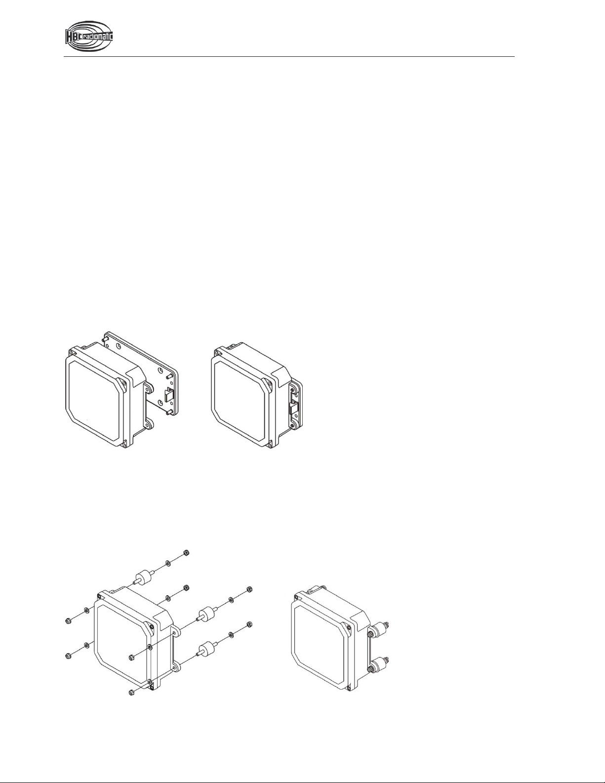
Installation
xThe receiver should be mounted vertically with the cable connection downwards.
xEnsure that there are no metal parts within a radius of 1 m (3 feet) above the receiver.
xWhen the receiver has to be mounted in a control cabinet, a car antenna must be installed.
xReceivers with external antenna must be installed in such a way that the antenna stands freely and
does not touch walls or metal parts. Otherwise a car antenna must be used, which can be supplied if
needed.
xReceivers with plastic housing should be protected against direct sunlight (UV radiation) by
appropriate measures.
Pos:17/TechnischeDokumentation/Betriebsanleitungen/Empfänger/VS_Montage mitWandhalterung@ 10\mod_1394801442922_48.docx@ 120361@ 2 @ 1
Installation with Snap-In Wall Bracket
The receiver is installed by means of the snap-in wall bracket included in the delivery. Install the wall
bracket with the provided drilling holes. Use only screws (max. M6) that are suitable to the installation
location.
Place the receiver with the eyelets on the wall bracket pins and press it on the wall bracket until it clicks
into place. Press the engagement pins outwards with a large screwdriver, to remove the receiver from the
wall bracket. This releases the receiver off the wall bracket from where it can be removed to the front.
Pos:18/TechnischeDokumentation/Betriebsanleitungen/Empfänger/VS_Montage mitBefestigungslaschen@ 10\mod_1394805357262_48.docx@ 120389@ 2 @ 1
Installation with Mounting Loops
The receiver is installed via the integrated mounting loops on the receiver sides. Use the shock mounts
provided for installation to dampen any vibrations that may occur.
Pos:19 /TechnischeDokumentation/Betriebsanleitungen/Allgemein/-----Seitenumbruch------ @1\mod_1219672326234_0.docx@ 29509 @ @ 1

7 / 13
Pos:22/TechnischeDokumentation/Betriebsanleitungen/Empfänger/ElektrischerAnschluss- K ontroll-Lampenfeld@ 10\mod_1398244692035_48.docx@122060@ 11 @ 1
Electrical Connection
Depending on the version, the radio receiver is connected to the machine electronics either via a cable
gland or with a Harting plug connection.
Please observe that the receiver may only be connected to the supply voltage indicated on the type plate!
Warning – shock hazard!
x
The electrical connection may only be carried out by skilled personnel.
x
The electrical connection must comply with the enclosed wiring diagram.
xSwitch off the supply voltage before opening the receiver. There is a risk of fatality from touching
live parts inside the housing!
Control Display
A control display with LEDs indicating the operating status of the radio system is located in the upper
housing part.
The LEDs have the following meaning:
Control display
Simplex procedure
(Data are only transmitted from the transmitter to the receiver.)
Meaning
Color
Receiver
On
yellow
Illuminates as soon as the receiver is connected to the
supply voltage.
RF
red
Illuminates as soon as the radio connection is interrupted.
Si1
green
Illuminates as soon as the E
-STOP relays are closed.
Si2
green
Illuminates as soon as a drive command is output.
Feedback
yellow
Off
.
(Not available for FSE 508 / 509 / 512.)
Control display
Duplex procedure
(Data are transmitted in both directions.
Non-safety-relevant data are transmitted in the feedback.)
Meaning
Color
Receiver
On
yellow
Illuminates as soon as the receiver is connected to the
supply voltage.
RF
red
Illuminates as soon as the radio connection is interrupted.
Si1
green
Illuminates as soon as the E
-STOP relays are closed.
Si2
green
Illuminates as soon as a drive command is output.
Feedback
yellow
Illuminates as soon as a feedback telegram is transmitted.
(Not available for FSE 508 / 509 / 512.)
Pos:23 /TechnischeDokumentation/Betriebsanleitungen/Allgemein/-----Seitenumbruch ------ @1\mod_1219672326234_0.docx @ 29509 @ @ 1

8 / 13
Pos: 28 /T ec hni sc h e D ok um en ta tio n/ Bet ri ebs anl ei tu nge n/T ec hni s ch e D at en /_Ü 1 - TD @ 1 \m od_ 1 221 55 283 49 3 7_4 8.d oc x @ 3502 6 @ 1 @ 1
Technical Data
Pos:29/TechnischeDokumentation/Betriebsanleitungen/TechnischeDaten/Empfänger/TD_VS_Standardempfänger_5XX_7XX@ 10\mod_1378109582277_0.docx@ 112162@ @ 1
Max. number of control commands
20 + E-STOP
(12 relays 12 V/2 A + 8 x semiconductor switches 12 V/1 A)
Unique system addresses
Over 1 000 000 combinations
Supply voltage
10 – 30 V DC
Power consumption
Max. 16 W
Inputs
-
Outputs
-
Interfaces
2 x PWM, 2 x 0 – 10 V or 0 – 20 mA
2 x Opto-In for feedback
E-STOP resp. Si1, Si2 control unit
1 x E-STOP output, 2 relays 4 A
Safety function
E-STOP:
Performance Level d, category 3 accor
ding to
EN ISO 13849-1:2008
Frequency ranges
405 – 475 MHz
1
, 865 – 870 MHz,
902
– 928 MHz, 1210 – 1258 MHz1
2,4 GHz: 2402
– 2480 MHz
DECT: 1790 – 1930 MHz
Channel spacing
12.5 / 20 / 25 / 50 / 250 kHz
2.4 GHz:
1 MHz
DECT: 1.728 MHz
Connection
Cable gland (metric M20/25)
Harting Han 16 or Han 25
Antenna
External, FL 30 or FL 70
Option: internal, car antenna with 5 m cable and BNC connector
Operating temperature range
-25 °C … +70 °C (-13 °F ... +158 °F)
Housing material
Plastic
Dimensions
165 x 165 x 70 mm (6.5 x 6.5 x 2.8 inches)
Weight
Approx. 1.0 kg (2.2 lbs.)
Protection class
IP 65
1Not all frequency ranges available.
Pos:31 /TechnischeDokumentation/Betriebsanleitungen/Allgemein/-----Seitenumbruch------ @1\mod_1219672326234_0.docx@ 29509 @ @ 1

9 / 13
Pos: 32 /T ec hni sc h e D o ku men ta tio n/ Be tri ebs anl eitu nge n/ Ab mes s ung en /_Ü 1 - A b mess ung e n @ 1 \ mo d_1 2 2164 5 928 87 5_4 8. do c x @ 3 506 0 @ 1 @ 1
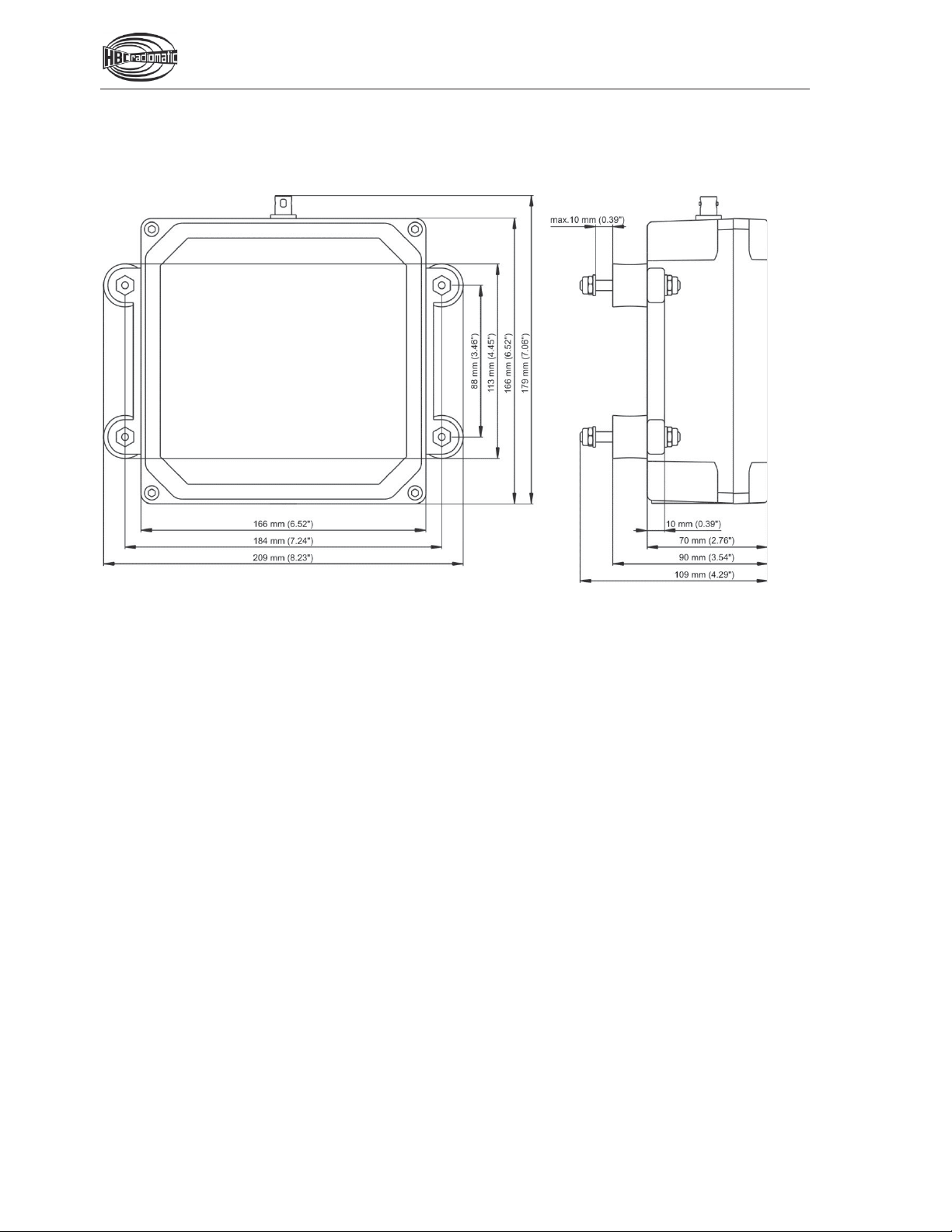
Dimensions
Pos:33/TechnischeDokumentation/Betriebsanleitungen/Abmessungen/Empfänger/Abmessungen_1_VS@ 11\mod_1401961009776_0.docx@ 123283@ 2 @ 1
Receiver Housing HR165 and Snap-In Wall Brackets
Pos:34 /TechnischeDokumentation/Betriebsanleitungen/Allgemein/-----Seitenumbruch ------ @1\mod_1219672326234_0.docx @ 29509 @ @ 1
10 / 13
Pos: 35 /T ec hni sc h e D ok um en ta tio n/ Bet ri ebs anl ei tu nge n/ Ab mes s ung en /E mpf äng er /A b mess ung en_2 _ VS @ 1 1\ mo d_1 4 0196 1 20 925 4 _0.d oc x @ 12 331 1 @ 2 @1
Receiver Housing HR165 with Shoch Mounts
Pos:36 /TechnischeDokumentation/Betriebsanleitungen/Allgemein/-----Seitenumbruch------ @1\mod_1219672326234_0.docx@ 29509 @ @ 1

11 / 13
Pos:37/TechnischeDokumentation/Betriebsanleitungen/Abmessungen/Empfänger/_Ü2_Anschlussmöglichkeiten@ 10\mod_1383232468716_48.docx@ 114087@ 2 @ 1
Connection Options
Pos:38/TechnischeDokumentation/Betriebsanleitungen/Abmessungen/Empfänger/Abmessungen_METRISCH_VS@ 11\mod_1402390361931_0.docx@ 123353@ @1
Metrical Cable Glands M20/25
Pos: 39 /T ec hni sc h e D ok um en ta tio n/ Bet ri ebs anl ei tu nge n/ Ab mes s ung en /E mpf äng er/A b mes s ung en _HAN _ VS @ 11 \ mo d_1 4 0239 0 415 25 2_0. d oc x @ 123381@ @ 1
Harting Plug Connection Han 16/25
Pos:41 /TechnischeDokumentation/Betriebsanleitungen/Allgemein/-----Seitenumbruch ------ @1\mod_1219672326234_0.docx @ 29509 @ @ 1
M
SW
A
B
C
M20
24 mm
5
-9 mm
36 mm
9 mm
M25
33 mm
9
-16 mm
42 mm
11 mm
12 / 13
Pos:42/TechnischeDokumentation/Betriebsanleitungen/Empfänger/Problembehandlung- Empfänger_USA@ 4\mod_1265621218004_48.docx@ 57 180 @ 1 @ 1
Troubleshooting
Note:
Please check the functions using the cabin or cable controls first!
Problem Possible Cause Measures
Transmitter does not react
when switched on
.
No power.
Check battery contacts for
damage or contamination.
Insert a fully
charged battery
into the battery compartment.
Recharge battery.
Low-power indication after
minimal operating time
.
Battery contacts are
contaminated or damaged.
Battery not charged.
Battery defective.
Check battery contacts for
damage or contamination.
Recharge battery.
Ensure that recharging
process runs correctly.
Check transmitter functions
using a fully charged or
replacement battery.
Some commands are not
carried out
.
Receiver defective.
Interruption in the connecting
cable to the crane or
machine.
Check if all connecting
cables and cable junctions
are tight.
If none of the measures mentioned resolve the problem, then please contact your service technician,
dealer or HBC-radiomatic, Inc.
Pos:43 /TechnischeDokumentation/Betriebsanleitungen/Allgemein/-----Seitenumbruch------ @1\mod_1219672326234_0.docx@ 29509 @ @ 1

13 / 13
Pos:44/TechnischeDokumentation/Betriebsanleitungen/Empfänger/Wartung - Empfänger @ 1\mod_1219741931000_48.docx@ 29945@ 1 @ 1
Maintenance
The radio control system is virtually maintenance-free. Please observe the following points:
xNever use a high pressure cleaner or sharp or pointed objects to clean the receiver.
xWhenever welding the machine:
Switch off the radio control system.
Switch off the machine.
Disconnect all electrical connections to the receiver.
Otherwise the receiver electronics can be destroyed.
Pos:45/TechnischeDokumentation/Betriebsanleitungen/Allgemein/ImFalle einesDefekts_USA@ 4\mod_1265299280289_48.docx@ 57026@ 4 @ 1
In the Event of a Fault
Warning:
Never operate a machine with a faulty or defective radio control system!
xNever try to repair the electronics of the radio control system! Opening the transmitter or receiver
housing terminates the manufacturer guarantee.
Send any defective or faulty equipment to your local distributor or to HBC-radiomatic, Inc. They
are experts and have the necessary know-how and OEM spare parts.
Always send both transmitter and receiver and enclose a detailed description of the problem.
Do not forget to enclose your address and telephone number so that we can get in touch with you
quickly if necessary.
xTo avoid damage during transport, use the original packing supplied with the transmitter and receiver,
otherwise pack securely. Send the consignment to your distributor or to the following address:
HBC-radiomatic, Inc.
1017 Petersburg Road
Hebron, KY 41048, USA
Telephone: +1 800 410-4562
Fax: +1 866 266-7227
xShould you decide to personally return a defective radio system to your distributor or
HBC-radiomatic, Inc., then please make an appointment first.
For an overview of our worldwide service and sales contacts, please visit our website
www.hbc-radiomatic.com under "Contact".
===Ende der Listefür T extmarkeI nhalt2===
Table of contents
Other HBC-Radiomatic Remote Control manuals


