HD AUDIO SYSTEM M-YL812 User manual
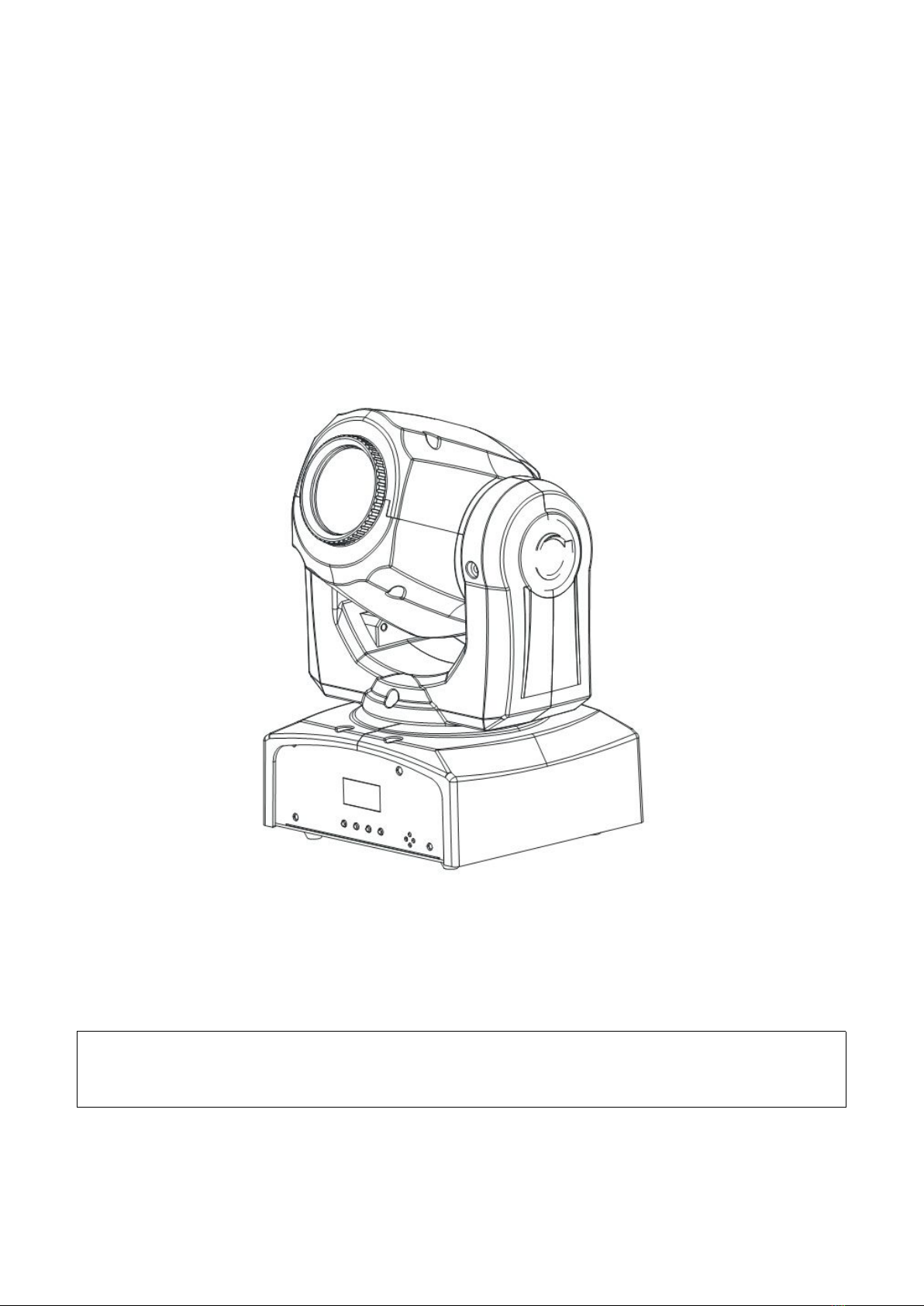
M-YL812 MINI SPOT MOVING HEAD
LIGHT
INSTRUCTION MANUAL
Thank you for choosing our LED mini spot moving head light. For the sake of your safety,
Please read and follow these instructions carefully and keep this manual in a safe place for
future reference.

2
Catalogue
Chapter Page
Safe Usage Of The Product -----------------------------------------------------------------------------------------3
Install The Equipment ------------------------------------------------------------------------------------------------4
DMX Set Up ------------------------------------------------------------------------------------------------------------5
System Menu ------------------------------------------------------------------------------------------------------------7
Home Adjustment Menu ---------------------------------------------------------------------------------------------10
Operation Menu ---------------------------------------------------------------------------------------------------------11
Master-Slave Set Up----------------------------------------------------------------------------------------------------12
Remote Operation-------------------------------------------------------------------------------------------------------12
DMX Channel Mode---------------------------------------------------------------------------------------------------13
Photometric Chart-------------------------------------------------------------------------------------------------------14
Dimmer Curve Chart---------------------------------------------------------------------------------------------------15
Fuse Replacement-------------------------------------------------------------------------------------------------------15
Cleaning--------------------------------------------------------------------------------------------------------------------15
Trouble Shooting---------------------------------------------------------------------------------------------------------16
Specifications--------------------------------------------------------------------------------------------------------------16
☆Important notice:
·In this instruction for use contains about the installment and the use aspect important information of the LED moving
head. When installing and using, you need to look this usage instruction strictly.
·Before open the LED moving head and if you want to do the repair work, please make sure the power source is at the
separation condition.
·Every unit is tested completely and packed properly by the manufacturer. Please make sure the packing and the unit are
in good condition before installation and use. Should there be any damage caused by transportation, consult your dealer
and do not use the unit. Any damage caused by improper use will not be assumed by the manufacturer or dealer.
Attention: Unceasingly carries on the product improvement about our company the policy, in this instruction booklet
carries the data will have the possibility to be able to change in the future, when no longer separate notice change matters
concerned. Our company retains when the product improvement changes the related specification the authority. This
instruction booklet publisher cannot be responsible regarding this instruction booklet in information accuracy, also cannot
the related consequence which causes regarding these information be responsible.
3
SAFE USAGE OF THE PRODUCT
When unpacking and before disposing of the carton, check there is no transportation damage before
using the product. Should there be any damage caused by transportation, consult your dealer and do
not use the apparatus.
The product is for indoor use only, IP20. Use only in dry locations. Keep this device away from rain
and moisture, excessive heat, humidity and dust. Do not allow contact with water or any other
liquids.
The product is not designed or intended to be mounted directly on to inflammable surfaces
The product is only intended for installation, operation and maintenance by professional person.
The product must be installed in a location with adequate ventilation, at least 50cm from MJacent
wall surfaces. Be sure that no ventilation slots are blocked.
Do not product the beam onto inflammable surfaces, minimum distance is m.
Avoid direct exposure to the light from the lamp. The light is harmful to the eye.
Do not attempt to dismantle or modify the projector in any way.
Electrical connection must only be carried out by qualified personnel.
Before installation, ensure that the voltage and frequency of power supply match the power
requirements of the projector.
It is essential that each projector is correctly earthed and that electrical installation conforms to all
relevant standards.
Do not connect this device to any other types of dimmer apparatus.
Make sure that the power-cord is never crimped or damaged by sharp edges. Never let the
power-cord come into contact with other cables. Only handle the power-cord by the plug. Never pull
out the plug by tugging the power-cord.
Keep the optical system clean. Do not touch the lens with bare hands.
The product should always be installed with a secondary safety fixing. On the projector base brink,
there is a hole for the safety cord provided. It should be attached as shown in “installing the
projector” section.
The lens shall be changed if they have become visibly damaged to such an extent that their
effectiveness is impaired, for example by cracks or deep scratches.
Exterior surface temperatures of the luminaire after 5 minutes operation is 40°C,
when steady state is
achieved 50°C.
There is no user serviceable parts inside the projector, do not open the housing and never operate the
product with the covers removed.
If you have any questions, don’t hesitate to consult your dealer or manufacturer.
★Always disconnect from the mains, when the device is not in use or before cleaning it or
before attempting any maintenance work !
4
Install The Equipment:
When installing the unit, the trussing or area of installation must be able to hold 10 times the weight without
any deformation. When installing the unit must be secured with a secondary safety attachment, e.g. and
appropriate safety cable. Never stand directly below the unit when mounting, removing, or servicing the unit.
Overhead mounting requires extensive experience, including calculating working load limits, installation
material being used, and perodic safety inspection of all installation material and unit. If you lack these
qualifications, do not attempt the installation yourself.
The installation should be checked by a skilled person once a year.
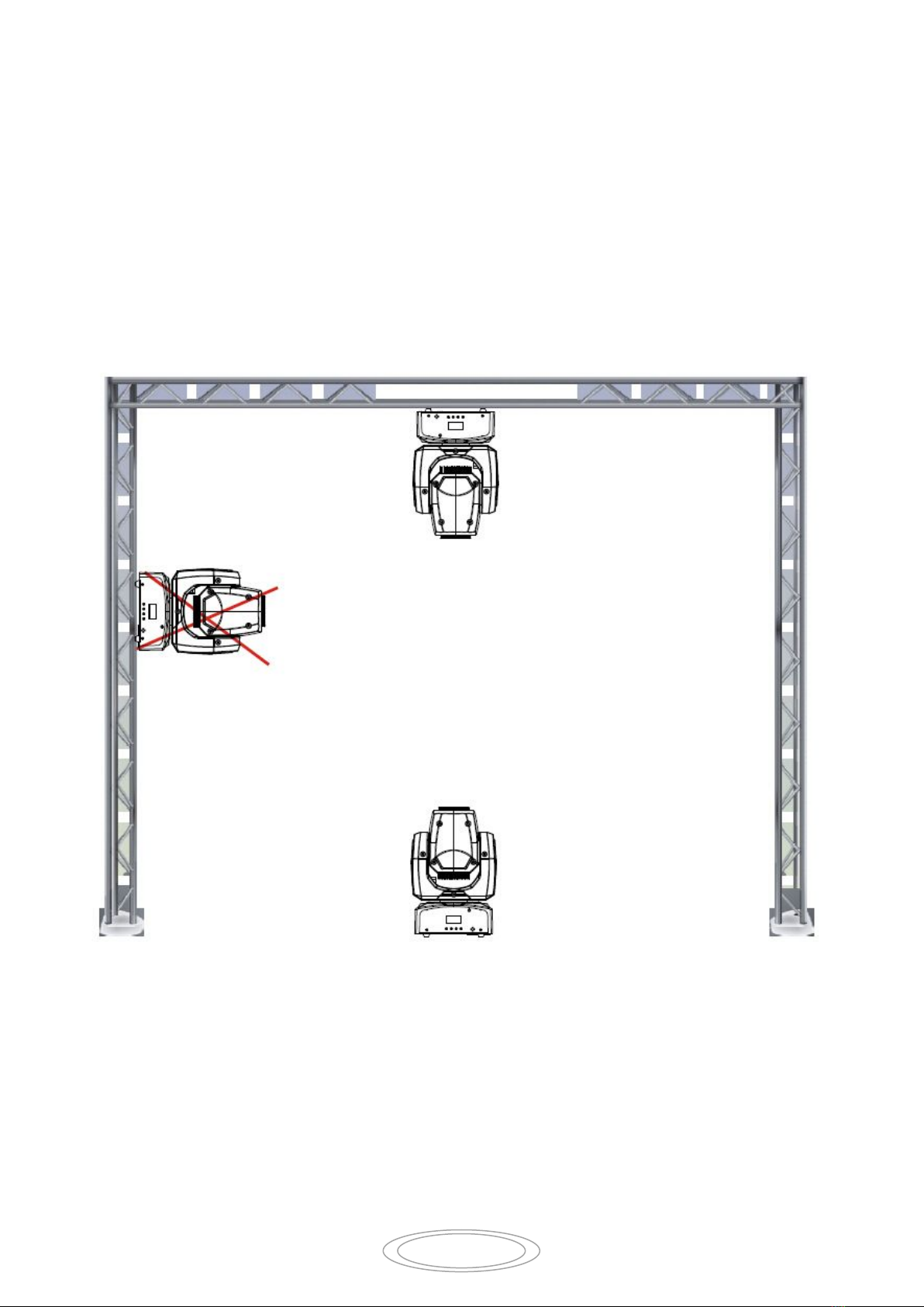
The Inno Pocket Spot Pearl is fully operational in two different mounting positions, hanging upside-down
from a ceiling or set on a flat level surface. To avoid internal damage to the unit, never mount the unit on its
side as illustrated above. Be sure this fixture is kept at least 0.5m away from any flammable materials
(decoration etc.). Always use and install the supplied safety cable as a safety measure to prevent accidental
damage and/or injury in the event the clamp fails (see next page).
NOTICE: The suitable enviromental temperature for this lighting fixture is between -25˚ C to 45˚ C. Do not place
this lighting fixture in an enviroment where the temperatures are under or above the temperatures stated above.
This will allow the fixture to run at its best and help prolong the fixture life.
5
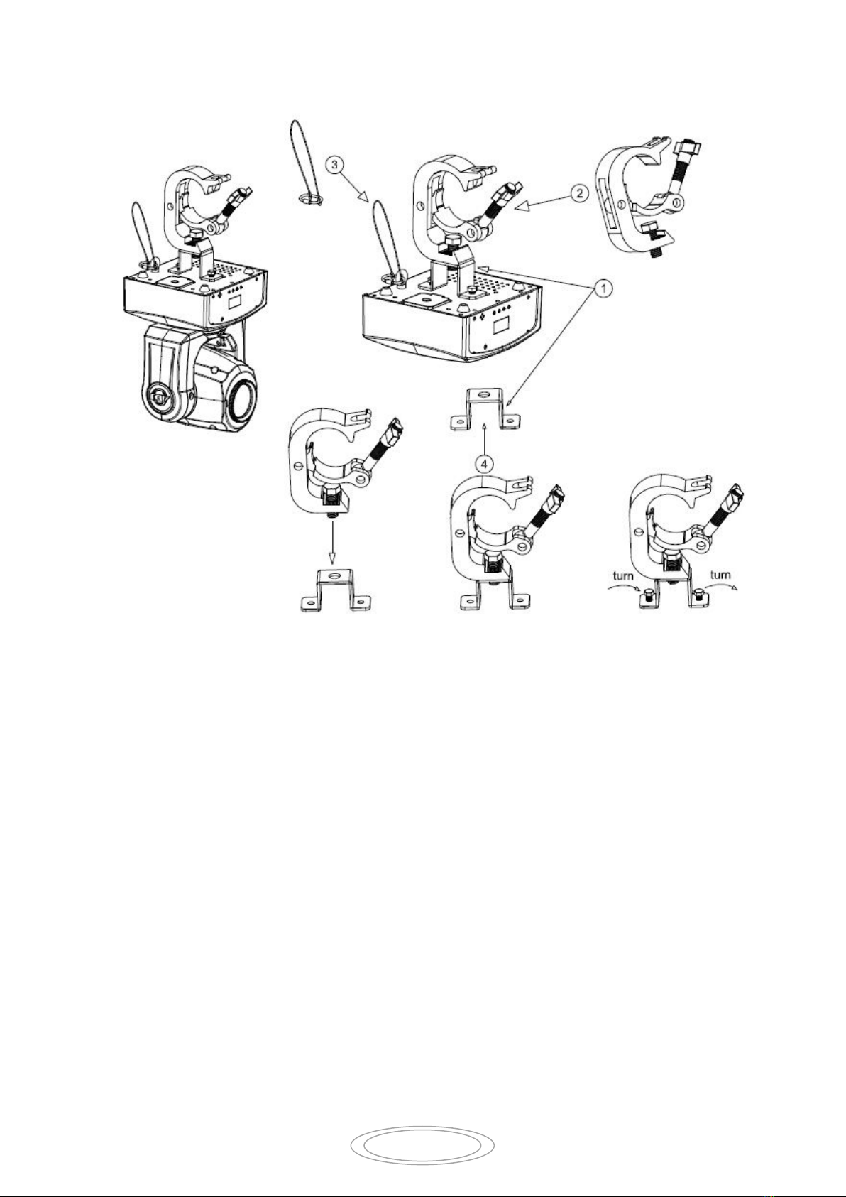
Screw one clamp via a M12 screw and nut to the included bracket. Attach the bracket using the included
screws to the bottom of the Inno Pocket Spot Pearl. Attach the eyehole screw to the bottom of the base
and pull the safety-cable through the screw and over the trussing system or a safe fixation spot. Insert the
end in the carabine and tighten the safety screw.
DMX Set Up
Power Supply: The MJ Inno Pocket Spot Pearl contains a automatic voltage switch, which will auto sense the
voltage when it is plugged into the power source. With this switch there is no need to worry about the correct
power voltage, this unit can be plugged in anywhere.
DMX-512: DMX is short for Digital Multiplex. This is a universal protocol used by most lighting and controller
manufactures as a form of communication between intelligent fixtures and controllers. A DMX controller sends
DMX data instructions from the controller to the fixture. DMX data is sent as serial data that travels from fixture to
fixture via the DATA “IN” and DATA “OUT” XLR terminals located on all DMX fixtures (most controllers only
have a DATA “OUT” terminal).
DMX Linking: DMX is a language allowing all makes and models of different manufactures to be linked together
and operate from a single controller, as long as all fixtures and the controller are DMX compliant. To ensure proper
DMX data transmission, when using several DMX fixtures try to use the shortest cable path possible. The order in
which fixtures are connected in a DMX line does not influence the DMX addressing. For example; a fixture

6
assigned a DMX address of 1 may be placed anywhere in a DMX line, at the beginning, at the end, or anywhere in
the middle. Therefore, the first fixture controlled by the controller could be the last fixture in the chain. When a
fixture is assigned a DMX address of 1, the DMX controller knows to send DATA assigned to address 1 to that unit,
no matter where it is located in the DMX chain.
Data Cable (DMX Cable) Requirements (For DMX and Master/Slave Operation): The Inno Pocket Spot Pearl
can be controlled via DMX-512 protocol. The Inno Pocket Spot Pearl two DMX channel modes; 9 channel mode &
11 channel mode. The DMX address is set electronically using the controls on the front panel of the unit. Your unit
and your DMX controller require a approved DMX-512 110 Ohm Data cable for data input and data output (Figure
1). We recommend Accu Cable DMX cables. If you are making your own cables, be sure to use standard 110-120
Ohm shielded cable (This cable may be purchased at almost all professional sound and lighting stores). Your
cables should be made with a male and female XLR connector on either end of the cable. Also remember that
DMX cable must be daisy chained and cannot be split.
Notice: Be sure to follow figures two and three when making your own cables. Do not use the ground lug on the
XLR connector. Do not connect the cable’s shield conductor to the ground lug or allow the shield conductor to
come in contact with the XLR’s outer casing. Grounding the shield could cause a short circuit and erratic behavior.
Special Note: Line Termination. When longer runs of cable are used, you may need to use a terminator on
the last unit to avoid erratic behavior. A terminator is a 110-120 ohm 1/4 watt resistor which is connected
between pins 2 and 3 of a male XLR connector (DATA + and DATA -). This unit is inserted in the female
XLR connector of the last unit in your daisy chain to terminate the line. Using a cable terminator (MJ part
number Z-DMX/T) will decrease the possibilities of erratic behavior.

7
5-Pin XLR DMX Connectors. Some manufactures use 5-pin DMX-512 data cables for DATA transmission
in place of 3-pin. 5-pin DMX fixtures may be implemented in a 3-pin DMX line. When inserting standard
5-pin data cables in to a 3-pin line a cable adaptor must be used, these adaptors are readily available at most
electric stores. The chart below details a proper cable conversion.
System Menu
DMX 512 Address setting
Channel Mode
Show Mode
Dimmer Mode
8
Slave Mode
Sound Mode
Sound Sense
Pan Inverse
Tilt Inverse
LED Display
Auto Test
Temperature Display
Reset
System Menu: When making MJ adjustments press ENTER to confirm your setup then press and hold
the MENU button for at least 3 seconds. To exit without making any adjustments press the MENU
button. The display will lock after 30 seconds, press the MENU button for 3 seconds to unlock.
ADDR - DMX Address Setting.
1. Press the either the MENU, UP, or DOWN buttons until “ADDR” is displayed, press ENTER.
2. The current address will now be displayed and flashing. Press the UP or DOWN buttons to find your
desired address. Press ENTER to set your desired DMX address.
Display Normal
Display Inversion

9
CHND - This will let select your desired DMX channel mode.
1. Press the either the MENU button until “CHND” is displayed, press ENTER. Either “9CH” or “11CH”
will be displayed
2. Press the UP or DOWN buttons to find your desired DMX channel mode and press ENTER to confirm and
exit.
SHND - Show modes 0-4 (Factory programs). Show mode can run with or without sound
active mode active.
1. Press the MENU button until “SHND” is displayed, press ENTER.
2. “Sh X” will now be displayed, “X” representing a number between 0-4. Shows 1-4 are factory programs,
while show “0” is random mode. Use the UP or DOWN buttons to find your desired show.
3. When you have found your desired show press ENTER, then press and hold the MENU button for at least 3
seconds to activate. After you have set your desired show, it can be changed at any time using the UP or
DOWN buttons.
DIND - This will let select your desired dimmer curve.
1. Press the either the MENU button until “DIND” is displayed, press ENTER. 1 of 5 dimmer curves will be
displayed. “STDA” (standard), “STGE” (stage), “TV” (TV), “ARAL” (theatrical), or “THAL” (Architectural).
2. Press the UP or DOWN buttons to find your desired dimmer curve and press ENTER to confirm and exit.
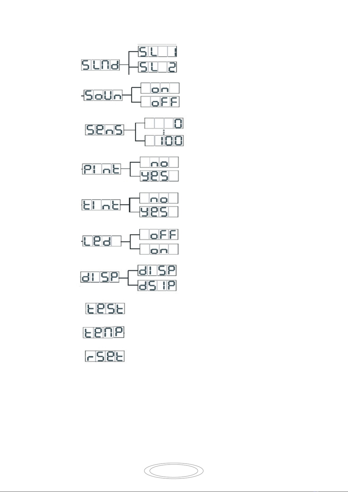
SLND - This will let you set unit as a master or slave in a master/slave configuration.
1. Press the MENU button until “SLND” is displayed, press ENTER. Either “MAST”, “SL 1”, or “SL 2” will
be displayed.
2. Press the UP or DOWN buttons until your desired setting is displayed, press ENTER to confirm.
NOTE: In a Master/Slave configuration you can set one fixture to Master and then set the next fixture to “SL
2”, the fixtures will now have contrast movement to each other.
SOUN - Sound Active mode.
1. Press the MENU button until “SOUN” is displayed, press ENTER.
2. The display will show either “ON” or “OFF”. Press the UP or DOWN buttons to select “ON” to activate
sound active mode, or “OFF” to deactivate sound active mode.
3. Press ENTER to confirm.
SENS - In this mode you can adjust the sound sensitivity.
1. Press the MENU button until “SENS” is displayed, press ENTER.
2. A number between 0-100 will be displayed. Press the UP or DOWN buttons to adjust the sound sensitivity.
0 being the least sensitive, and 100 being the most sensitive.
3. When you have found your desired setting press ENTER to confirm.
PINT - Pan Inversion
1. Press the MENU button until “PINT” is displayed, press ENTER. Either “Yes” or “No” will be displayed.
2. To activate the Pan inversion press the UP or DOWN buttons until “Yes” is displayed, press ENTER to
confirm. To deactivate Pan inversion, select “No” and press Enter.

10
TINT - Tilt Inversion
1. Press the MENU button until “TINT” is displayed, press ENTER. Either “Yes” or “No” will be displayed.
2. To activate the tilt inversion press the UP or DOWN buttons until “Yes” is displayed, press ENTER to
confim. To deactivate tilt inversion, select “No” and press Enter.
LED - With this function you can have the LED display turn off after 10 seconds.
1. Press the MENU button until “LED” is displayed, press ENTER.
2. The display will show either “ON” or “OFF”. Press the UP or DOWN buttons to select “ON” to keep the
LED display on at all times, or “OFF” to switch to have the LED display switch off after 10 seconds.
3. Press ENTER to confirm. To make you LED display reappear again press any button.
DISP - This function will reverse the display 180º.
1. Press the MENU button until “DISP” is displayed, press ENTER.
2. Press ENTER to “flip” the display. Press ENTER to “flip” it again. Press ENTER when you have made
your desired setup.
TEST - This function will run a self test program.
1. Press the MENU button until “TEST” is displayed, press ENTER.
2. The fixture will now run a self test.
TENP - Use this function to display the temperature of the unit.
1. Press the either the MENU button until “TENP” is displayed, press ENTER.
2. The display will show the temperature .
RSET - Use this function to reset the unit.
1. Press the MENU button until “RSET” is displayed, press ENTER.
2. The fixture will now reset.
Home Adjustment Menu

11
To enter the home position adjustment menu, press the ENTER button for at least 5 seconds. In this submenu
you are able to adjust the original position of the pan position, tilt position, color wheel position, and gobo
wheel position.
OPAN - adjustment of the pan position.
1. Press the ENTER button for at least 5 seconds, then press the UP or DOWN buttons so that “OPAN” is
displayed, press ENTER.
2. Use the UP and DOWN buttons to make your adjustments, and then press ENTER to confirm. Press the
MENU button for one second to exit.
OTIL - adjustment of the tilt position.
1. Press the ENTER button for at least 5 seconds, then press the UP or DOWN buttons so that “OTIL” is
displayed, press ENTER.
2. Use the UP and DOWN buttons to make your adjustments, and then press ENTER to confirm. Press the
MENU button for one second to exit.
OGOB - adjustment of the gobo wheel.
1. Press the ENTER button for at least 5 seconds, then press the UP or DOWN buttons so that “OGOB” is
displayed, press ENTER.
2. Use the UP and DOWN buttons to make your adjustments, and then press ENTER to confirm. Press the
MENU button for one second to exit.
OCOL - adjustment for the color wheel.
1. Press the ENTER button for at least 3 seconds, then press the UP or DOWN buttons so that “OCOL” is
displayed, press ENTER.
2. Use the UP and DOWN buttons to make your adjustments, and then press ENTER to confirm. Press the
MENU button for one second to exit.
Operation
Universal DMX Control: This function allows you to use a Elation®universal DMX-512 controller to
control the chases and patterns, dimmer and strobe. A DMX controller allows you to create unique programs
tailored to your individual needs.
1. The Inno Pocket Spot Pearl has 2 DMX channel modes; 9 channel mode or 11 channel mode. See pages
20-23 for detailed description of the DMX values and traits.
2. To control your fixture in DMX mode, follow the set-up procedures on pages 5-7 as well as the set-up
specifications that are included with your DMX controller.
3. Use the controller’s faders to control the various DMX fixture traits.
4. This will allow you to create your own programs.
5. Follow the instruction on page 9 to set the DMX address.
6. For longer cable runs (more than a 100 feet) use a terminator on the last fixture.
7. For help operating in DMX mode consult the manual included with your DMX controller.
Sound Active Mode: This mode allows either single unit or several units linked together, to run to the beat
of the music.

12
1. Press the MENU button until “SOUN” is displayed, and press ENTER. Press the UP or DOWN buttons so
that “ON” is displayed and press ENTER.
2. Press the MENU button until “SENS” is displayed, and press ENTER. Use the UP and DOWN buttons to
adjust the sound
sensitivity. Press ENTER when you have found your desired sensitivity level.
Show Mode: This mode allows either a single unit or several units linked together, to run one of four shows
that you choose.
1. Press the MENU button until “SHND” is displayed, and press ENTER.
2. Press the UP or DOWN buttons until you find your desired show, and press ENTER.
Master-Slave Set Up
Master-Slave Operation This function will allow you to link up to 16 units together and operate without a
controller. The units will be sound activated. In Master-Slave operation one unit will act as the controlling unit
and the others will react to the controlling units programs. Any unit can act as a Master or as a Slave.
1. Using approved DMX data cables, daisy chain your units together via the XLR connector on the rear of the
units. Remember the Male XLR connector is the input and the Female XLR connector is the output. The first
unit in the chain (master) will use the female XLR connector only - The last unit in the chain will use the male
XLR connector only. For longer cable runs we suggest a terminator at the last fixture.
2. On the Master unit press the MENU button until “SLND” is displayed, and press ENTER. Use the UP and
DOWN buttons to scroll to the “MAST” setting and press ENTER.
3. After setting the Master unit to the master setting find your desired operating mode.
4. On the slave units press the MENU button until “SLND” is displayed, and press ENTER. Choose either
“SL 1” or “SL 2” and press ENTER. See page 10 for more info.
5. The slave units will now follow the Master unit.
Remote Operation
ButtonCode
Function
FULL ON/OFF
STROBE
1. Synchronous strobe
2. Master-slave strobe
3. Sound strobe
GOBO
Gobo mode
COLOR
Color mode
DIMMER+
adjust the output intensity +
DIMMER -
adjust the output intensity -
SOUND ON
Sound ON
SOUND OFF
Sound OFF
SHOW 0
Show mode (1-9)
13
The UC-IR infrared remote gives you control of various functions (See below). To control the fixture you
must aim the remote at the front of the fixture and be no more then 30 feet away.
STAND BY - Pressing this button will blackout the fixture.
FULL ON - Hold this button down to fully light up the unit. When you let the button go, the unit will return
to its previous state.
FADE/GOBO - Press this button to enter Gobo mode. Use the 1-9 buttons to select your desired gobo. Adjust
the output intensity using the “DIMMER +” and “DIMMER -” buttons.
“DIMMER +” and “DIMMER -” - Use these buttons to adjust the output intensity and to adjust the strobe
speed.
STROBE - This button will activate the strobe effect. You can control the flash rate by pressing the
“DIMMER +” and “DIMMER -” buttons. If you press and hold this button the unit will begin to strobe.
COLOR - Press this button to enter Dimmer mode. Use the 1-9 buttons to select your desired color. Adjust
the output intensity using the “DIMMER +” and “DIMMER -” buttons.
1-9 - When in either Gobo mode or Color mode, these buttons will allow you to select either a gobo or color.
SOUND ON & OFF - These buttons activate and deactivate the sound active mode.
SHOW - This activates the show mode. Use the 1-9 buttons to select your desired mode .
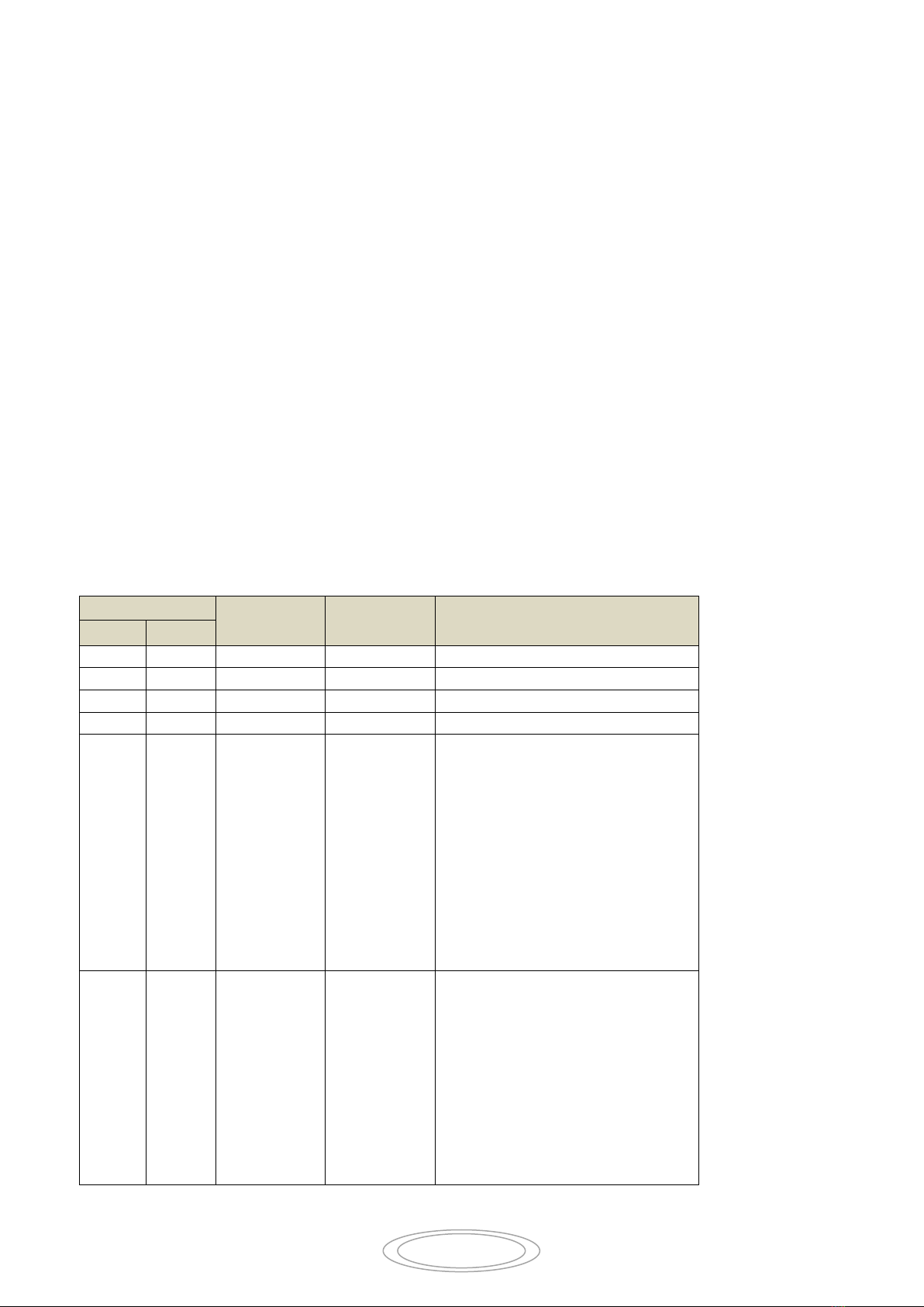
DMX Channel Mode
Channel Mode
Function
Value
Percent / Setting
9CH
11CH
1 CH
1CH
Pan
000-255
0~100%
2CH
Pan Fine
000-255
0~100%
2 CH
3CH
Tilt
000-255
0~100%
4 CH
Tilt Fine
000-255
0~100%
3 CH
5 CH
Color
000-015
016-031
032-047
048-063
064-079
080-095
096-111
112-127
128-189
190-193
194-255
Color 1
Color 2
Color 3
Color 4
Color 5
Color 6
Color 7
Color 8
Color Scroll Fast to Slow
Stop
Color Scroll Slow to Fast
4 CH
6 CH
Gobo
000-007
008-015
016-023
024-031
032-039
040-047
048-055
056-063
064-071
072-079
Gobo 1
Gobo 2
Gobo 3
Gobo 4
Gobo 5
Gobo 6
Gobo 7
Gobo 8
Gobo 1 Shake
Gobo 2 Shake
14
080-087
088-095
096-103
104-111
112-119
120-127
128-189
190-193
194-255
Gobo 3 Shake
Gobo 4 Shake
Gobo 5 Shake
Gobo 6 Shake
Gobo 7 Shake
Gobo 8 Shake
Gobo Scroll, Fast to Slow
Stop
Gobo Scroll , Slow to Fast
5 CH
7 CH
Shutter
000-007
008-015
016-131
132-139
140-181
182-189
190-231
232-239
240-247
248-255
Close
Open
Strobe Slow->Fast
Open
Fast Close Slow Open
Open
Fast Open Slow Close
Open
Random Strobe
Open
6
8 CH
Dimmer
000-255
0~100%
7
9 CH
Pan/Tilt
Speed
000-255
Fast -> Slow
8 CH
10 CH
Function
000-069
070-079
080-089
090-099
100-109
110-119
120-199
200-209
210-249
250-255
Null
Blackout while Pan/Tilt Move
Null
Blackout when Color changes
Null
Blackout when Gobo changes
Null
Reset All
Null
Sound Active
9 CH
11 CH
Dim Modes
000-020
021-040
041-060
061-080
081-100
101-255
Standard
Stage
TV
Architectural
Theatre
Default to Unit
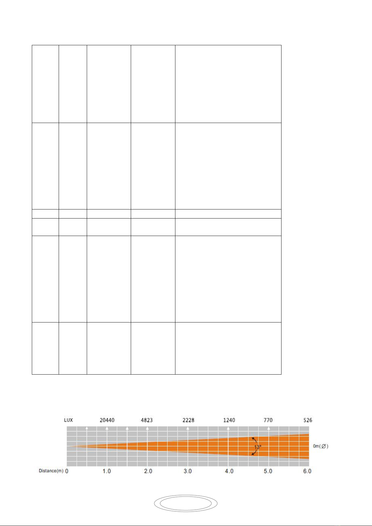
Photometric Chart

15
Dimmer Curve Chart
Fuse Replacement
Locate and remove the unit’s power cord. Once the cord has been removed located the fuse holder located
inside the power socket. Insert a flat-head screw driver into the power socket and gently pry out the fuse
holder. Remove the bad fuse and replace with a new one. The fuse holder has a built-in socket for a spare fuse
be sure not to confuse the spare fuse with active fuse.
Cleaning
Due to fog residue, smoke, and dust cleaning the internal and external optical lenses and mirror should be carried
out periodically to optimize light output. Cleaning frequency depends on the environment in which the fixture
operates (I.e. smoke, fog residue, dust, dew). In heavy club use we recommend cleaning on a monthly basis.
Periodic cleaning will ensure longevity, and crisp output.
1. Use normal glass cleaner and a soft cloth to wipe down the out- side casing.
2. Use a brush to wipe down the cooling vents and fan grill.
3. Clean the external optics with glass cleaner and a soft cloth every 20 days.
4. Clean the internal optics with glass cleaner and a soft cloth every 30-60 days.
5. Always be sure to dry all parts completely before plugging the unit back in.

16
Trouble Shooting
Trouble Shooting: Listed below are a few common problems that you may encounter, with solutions.
No light output from the unit;
1. Be sure the external fuse has not blown. The fuse is located on the rear panel of the unit.
2. Be sure the fuse holder is completely and properly seated.
Unit does not respond to sound;
1. Low frequencies (bass) should cause the unit to react to sound.
Tapping on the microphone, quiet or high pitched sounds may
not activate the unit.
Specifications
Voltage: 100 - 240V, 50/60Hz
LED: 1 x 12W White Cree LED
Power Consumption: 26W @ 120V
27W @ 230V
Dimensions: 6.25”(L) x 5.75”(W) x 10.5”(H)
159mm x 147mm x 265mm
Weight: 7 Lbs. / 3 kgs.
Beam Angle: 13 Degrees
Fuse: 3 Amp
Duty Cycle: None
DMX: 2 DMX Channel Modes: 9 Channel Mode & 11 Channel Mode
Colors: 7 + White
Gobos: 7 + Spot
Sound Active: Yes
Working Position: Any Safe, Secure Position
Warranty: 2 Year (730 days)
Please Note: Specifications and improvements in the design of this unit and this manual are subject
to change without any prior written notice.
Auto Sensing Voltage: This fixture contains a automatic voltage switch, which will auto sense the
voltage when it is plugged into the power source.
HD AUDIO SYSTEM INC.
ADDRESS : 2112 Lee Ave. South El Monte, CA 91733
TELEPHONE : +1 (626) 433-0357 +1 (844) 223-7809
FAX : +1 (626) 433-0315
EMAIL : info@hdaudiosystem.com
Table of contents
Other HD AUDIO SYSTEM Lighting Equipment manuals


Popular Lighting Equipment manuals by other brands


Lightolier
Lightolier Lightolier E1 Series Specifications

ACME
ACME XP-5000WZ user manual

Lichtlauf
Lichtlauf Ledl instruction manual

IKEA
IKEA LEDBERG manual

Alladin
Alladin BI-FABRIC 2 Bi-Color user manual

Public Safety Equipment
Public Safety Equipment Code 3 DuoBeam II DB2-2LMCNFPA1 Installation & operation manual


