Vega VEGAMET 381 Ex User manual

Operating Instructions
VEGAMET 381 Ex
4…20 mAsignal conditioning instru-
ment
in out

Contents
1About this document
1.1Function ............................. 4
1.2Target group .......................... 4
1.3Symbolism used ....................... 4
2For your safety
2.1Authorised personnel .................... 5
2.2Appropriate use........................ 5
2.3Warning about misuse ................... 5
2.4CE conformity ......................... 5
2.5Safety instructions for Ex areas ............ 6
2.6Environmental instructions ................ 6
3Product description
3.1Configuration.......................... 7
3.2Principle of operation.................... 8
3.3Operation ............................ 8
3.4Storage and transport ................... 8
4Mounting
4.1General instructions..................... 9
4.2Mounting instructions.................... 9
5Connecting to voltage supply
5.1Preparing the connection ................. 11
5.2Connection procedure ................... 12
5.3Wiring plan ........................... 13
6Setup with the integrated indicating and adjustment
unit
6.1Adjustment system ..................... 15
6.2Setup procedure ....................... 16
6.3Application example..................... 20
7Maintenance and fault rectification
7.1Maintenance .......................... 23
7.2Rectify faults .......................... 23
7.3Instrument repair ....................... 24
8Dismounting
8.1Dismounting procedure .................. 25
8.2Disposal ............................. 25
2VEGAMET 381 Ex-4…20 mAsignal conditioning instrument
Contents
30418-EN-060925

9Supplement
9.1Technical data......................... 26
9.2Dimensions ........................... 29
VEGAMET 381 Ex-4…20 mAsignal conditioning instrument 3
Contents
30418-EN-060925

1About this document
1.1Function
This operating instructions manual has all the information you
need for quick setup and safe operation.Please read this
manual before you start setup.
1.2Target group
This operating instructions manual is directed to trained
personnel.The contents of this manual should be made
available to these personnel and put into practice by them.
1.3Symbolism used
Information,tip,note
This symbol indicates helpful additional information.
Caution:If this warning is ignored,faults or
malfunctions can result.
Warning:If this warning is ignored,injury to persons and/or
serious damage to the instrument can result.
Danger:If this warning is ignored,serious injury to persons
and/or destruction of the instrument can result.
Ex applications
This symbol indicates special instructions for Ex applications.
lList
The dot set in front indicates a list with no implied sequence.
àAction
This arrow indicates a single action.
1Sequence
Numbers set in front indicate successive steps in a procedure.
4VEGAMET 381 Ex-4…20 mAsignal conditioning instrument
About this document
30418-EN-060925

2For your safety
2.1Authorised personnel
All operations described in this operating instructions manual
must be carried out only by trained specialist personnel
authorised by the operator.For safety and warranty reasons,
any internal work on the instruments must be carried out only
by personnel authorised by the manufacturer.
2.2Appropriate use
VEGAMET 381 Ex is a universal signal conditioning instrument
and power supply unit for connection of a 4…20 mA/HART
sensor.
2.3Warning about misuse
Inappropriate or incorrect use of the instrument can give rise to
application-specific hazards,e.g.vessel overfill or damage to
system components through incorrect mounting or adjustment.
2.4General safety instructions
The VEGAMET 381 Ex is a high-tech instrument requiring the
strict observance of standard regulations and guidelines.The
user must take note of the safety instructions in this operating
instructions manual,the country-specific installation standards
(e.g.the VDE regulations in Germany)as well as all prevailing
safety regulations and accident prevention rules.
2.5CE conformity
VEGAMET 381 ExisinCE conformity with EMC (89/336/
EWG)and LVD (73/23/EWG).
Conformity has been judged according to the following
standards:
lEMC:
-Emission DIN/EN 61326:2004
-Susceptibility DIN/EN 61326:2004 incl.supplement A
lLVD:EN 61010-1:2001
VEGAMET 381 Ex-4…20 mAsignal conditioning instrument 5
For your safety
30418-EN-060925

2.6Safety instructions for Exareas
Please note the Ex-specific safety information for installation
and operation in Ex areas.These safety instructions are part of
the operating instructions manual and come with the Ex-
approved instruments.
2.7Environmental instructions
Protection of the environment is one of our most important
duties.That is why we have introduced an environment
management system with the goal of continuously improving
company environmental protection.The environment man-
agement system is certified according to DIN EN ISO 14001.
Please help us fulfil this obligation by observing the environ-
mental instructions in this manual:
lChapter "Storage and transport"
lChapter "Disposal"
6VEGAMET 381 Ex-4…20 mAsignal conditioning instrument
For your safety
30418-EN-060925

3Product description
3.1Configuration
The scope of delivery encompasses:
lIndicating and signal conditioning instrument VEGAMET
381 Ex
lMounting set
lEx separating chamber
lIdentification label
lDocumentation
-this operating instructions manual
-Ex specific safety instructions and,if necessary,further
certificates.
0
1
2
3
4
5
6
7
8
9
A
B
C
-+
12
1
3
8
7
6
5
2
4
Fig.1:VEGAMET 381 Ex
1Status indication operating relay 1and 2
2Status indication fail safe relay
3Status indication operation
4[+/-]adjustment keys
5Insertable tag for identification of the measurement loop
6Function switch
7Mode switch for sensor input (active/passive)on the rear of the instrument
8LC display
Scope of delivery
Overview
VEGAMET 381 Ex-4…20 mAsignal conditioning instrument 7
Product description
30418-EN-060925

3.2Principle of operation
VEGAMET 381 Ex is a universal single signal conditioning
instrument with integrated level switches and display for
continuously measuring sensors.At the same time,it can
serve as power supply unit for connected sensors.VEGAMET
381 Ex is designed for connection of an individual 4…20 mA
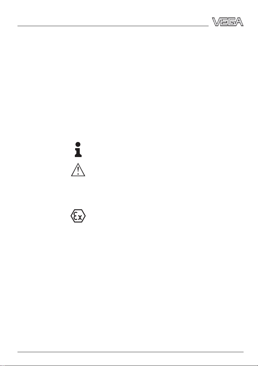
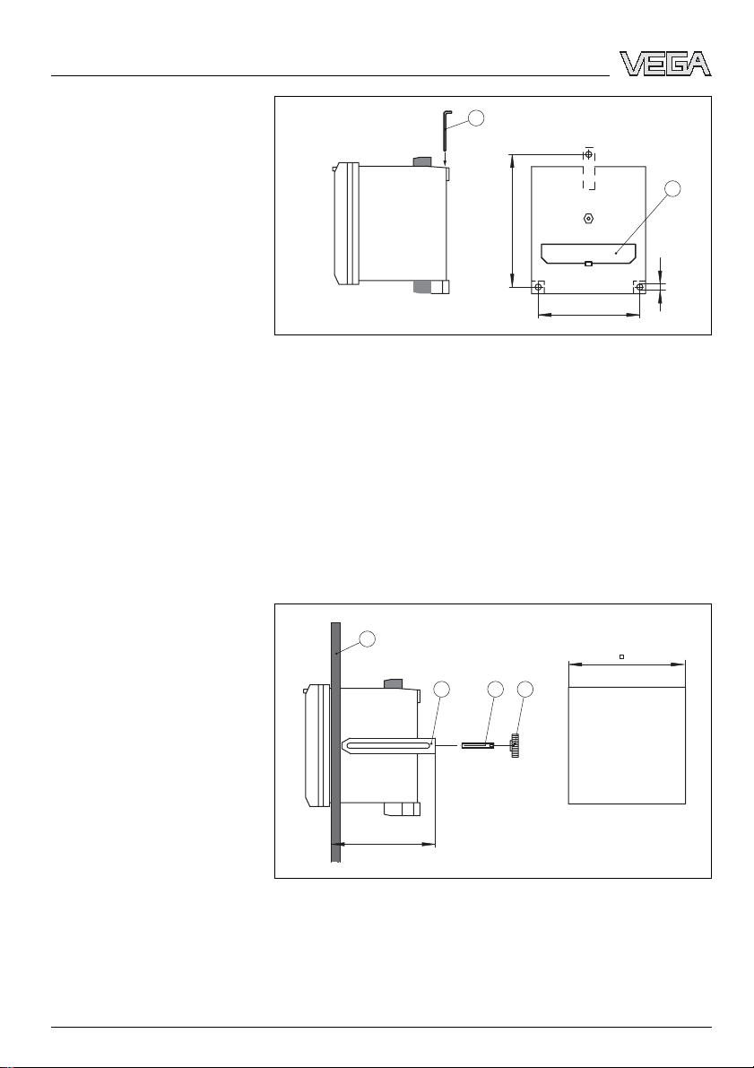
sensor.The instrument is suitable for carrier rail,panel and
surface mounting.
The VEGAMET 381 Ex signal conditioning instrument can
power connected sensors and process their measured
signals.The requested parameter is displayed and outputted
in addition to the integrated current output for further
processing.Hence the measured signal can be transferred to
a remote indication or a superordinate control system.Two
level relays for control of pumps or other actors are also
integrated.
Wide-range power supply unit with 20 …253 VAC/DC for
world-wide use.
You can find detailed information on the power supply in the
"Technical data"in the "Supplement".
3.3Operation
The adjustment of VEGAMET 381 Ex is carried out via the
integrated keys and a 16-step function switch.
3.4Storage and transport
Your instrument was protected by packaging during transport.
Its capacity to handle normal loads during transport is assured
by a test according to DIN EN 24180.
The packaging of standard instruments consists of environ-
ment-friendly,recyclable cardboard.For special versions,PE
foam or PE foil is also used.Dispose of the packaging material
via specialised recycling companies.
lStorage and transport temperature see "Supplement -
Technical data -Ambient conditions"
lRelative humidity 20 …85 %
Area of application
Physical principle
Power supply
Packaging
Storage and transport tem-
perature
8VEGAMET 381 Ex-4…20 mAsignal conditioning instrument
Product description
30418-EN-060925

4Mounting
4.1General instructions
You can mount theVEGAMET 381 Ex signal conditioning
instrument onto a carrier rail 35x7.5acc.to DIN EN 50022,or
directly on the wall by means of the three screws or in a front
panel or door of a switching cabinet.
Note:
Before mountingVEGAMET 381 Ex,set the requested mode
of the measuring data input.With a slide switch on the rear of
the instrument you can choose between active and passive
current input (see also chapter "Connecting to power supply
"). After mounting the instrument,the slide switch is no longer
accessible.
4.2Mounting instructions
1Place the adapter plate [1]to the rear of VEGAMET 381 Ex
(spring of the adapter plate downward)and fasten the plate
with screw [2](M4x6).
2PlaceVEGAMET 381 Ex against the carrier rail [3]from
below and push the instrument upward until it snaps in.
61
43,5
21 3
Fig.2:Carrier rail mounting
1Adapter plate
2Screw (M4x6)
3Carrier rail
1Insert the metal strap [1]from above into the housing cut-
out.
2Fasten the instrument directly to the wall with the three
screws (ømax.4mm).
Installation location
Carrier rail mounting
Wall mounting
VEGAMET 381 Ex-4…20 mAsignal conditioning instrument 9
Mounting
30418-EN-060925

105
80
ø 4,5*
1
2
Fig.3:Wall mounting
1Metal strap
2Covering slide switch active-passive
1Remove the pluggable terminal strips from the top and
bottom.
2Screw pin [3]into the rear of VEGAMET 381 Ex and tighten
with a screwdriver.
3Insert VEGAMET 381 Ex from the front into the front panel
[1].
4Place the clamping strap [2]from the back over the pin [3]
and pull it with the knurled nut [4]against the panel [1].
~90
92
1
32 4
Fig.4:Front panel mounting
1Front panel
2Terminal strap
3Pin
4Knurled nut
Front panel mounting
10 VEGAMET 381 Ex-4…20 mAsignal conditioning instrument
Mounting
30418-EN-060925

5Connecting to voltage supply
5.1Preparing the connection
Generally not the following safety instructions:
lConnect only in the complete absence of line voltage
lIf overvoltage surges are expected,overvoltage arresters
should be installed
Tip:
We recommend VEGA overvoltage arresters B61-300 (power
supply VEGAMET 381 Ex)and B62-36G(sensor supply).
In hazardous areas you should take note of the appropriate
regulations,conformity and type approval certificates of the
sensors and power supply units.
The power supply can be 20 …253 VAC,50/60 Hzor
20 …253 VDC.
Power supply of VEGAMET 381 Ex is connected with standard
cable according to the national installation standards.
Standard two-wire cable without screening can be used to
connect sensors.If electromagnetic interference is expected,
screened cable must be used.
Connect the cable screen on both ends to ground potential.In
the sensor,the screen must be connected directly to the
internal ground terminal.The ground terminal outside on the
sensor housing must be connected to the potential equal-
isation.
If potential equalisation currents are expected,the screen
connection on the side of VEGAMET 381 Ex must be made via
a ceramic capacitor (e.g.1nF,1500 V). The low frequency
potential equalisation currents are thus suppressed,but the
protective effect against high frequency interference signals
remains.
Take note of the corresponding installation regulations for Ex
applications.In particular,make sure that no potential equal-
isation currents flow over the cable screen.In case of
grounding on both sides this can be achieved by the use of a
capacitor or a separate potential equalisation.
Note safety instructions
Take note of safety
instructions for Ex
applications
Select power supply
Selecting connection cable
Cable screening and ground-
ing
Select connection
cable for Ex applica-
tions
VEGAMET 381 Ex-4…20 mAsignal conditioning instrument 11
Connecting to voltage supply
30418-EN-060925

5.2Connection procedure
Proceed as follows:
1Mount VEGAMET 381 Ex
2Connect sensor cable to terminal 1and 2,and where
applicable,connect the screen
3Connect power supply (switched off)to terminal 5and 6
4If necessary,connect fail safe and operating relay as well
as current output
The electrical connection is hence finished.
After connection,it is absolutely necessary to plug the blue Ex
separating chamber to terminals 1and 2(sensor input). This
ensures the required distance of at least 50 mm (1.97 in)to
other instruments.
1Place the Ex separating chamber as shown below on the
terminals of the sensor input
2Lead the sensor cable towards the front and out of the Ex
separating chamber
3Push the Ex separating chamber towards the front until you
hear it snap in
12 VEGAMET 381 Ex-4…20 mAsignal conditioning instrument
Connecting to voltage supply
30418-EN-060925

5.3Wiring plan
+-
12
+-
34
18 17 16 15 14 13 1211 10 9 8 76 5
N- L1+
on
1
2
12
%
1 2
3 4 5 6
Fig.5:Terminal assignment VEGAMET 381 Ex
1Meas.data input/sensor power supply with sockets for VEGACONNECT
2Current output
3Fail safe relay
4Relay 2
5Relay 1
6Supply voltage
Overview
VEGAMET 381 Ex-4…20 mAsignal conditioning instrument 13
Connecting to voltage supply
30418-EN-060925

Information:
Via the slide switch on the rear of the instrument you can
switch over between active and passive operation of the
measuring data input:
lIn active mode,VEGAMET 381 Ex provides the power for
the connected sensors.Power supply and measurement
data are transmitted over the same two-wire cable.This
mode is provided for connection of transmitters without
separate power supply (sensors in two-wire version).
lIn passive mode the sensors are not powered,only the
measured value is transmitted.This input is for connection
of transmitters with own,separate voltage supply (sensors
in four-wire version). The VEGAMET 381 Ex can be also
connected into the existing circuit like a normal current
meter.
The position of the slide switch also influences the precondi-
tions for Ex implementation.Take note of the type approval
certificate or the conformity certificate ofVEGAMET 381 Ex.
Tip:
For parameter adjustment of connected HART sensors,the
sockets are integrated in the terminals of the meas.data input.
A VEGACONNECT can be directly plugged in without the
need of an additional HART resistor.
14 VEGAMET 381 Ex-4…20 mAsignal conditioning instrument
Connecting to voltage supply
30418-EN-060925

6Setup with the integrated indicating and
adjustment unit
6.1Adjustment system
The integrated indicating and adjustment unit is for measured
value display,adjustment and diagnosis ofVEGAMET 381 Ex.
Indication and adjustment is carried out in the front via a clear
LC-display and a function switch as well as two keys.
To open the cover,insert a screwdriver in the two slots on the
top and turn it slightly.
0
1
2
3
4
5
6
7
8
9
A
B
C
-+
12
1
3
8
7
6
5
2
4
Fig.6:Indicating and adjustment elements
1Status indication operating relay 1and 2
2Status indication fail safe relay
3Status indication operation
4[+/-]adjustment keys
5Insertable tag for identification of the measurement loop
6Function switch
7Mode switch for sensor input (active/passive)on the rear of the instrument
8LC display
VEGAMET 381 Ex-4…20 mAsignal conditioning instrument 15
Setup with the integrated indicating and adjustment unit
30418-EN-060925

l[Function switch]for selection of:
-Adjustment
-Relay switching points
-Indication scaling
-Current output
-Integration time
-Offset correction
l[+/-]key:
-Change value of the parameter
By pushing the [+/-]key,you change the individual parameters
of the selected function.In this phase,the processed
parameter is flashing.By briefly pushing the two keys
simultaneously,you save your settings."Save"is briefly
displayed.
6.2Setup procedure
The setup comprises first of all the adjustment of the
measurement loop.Ascaling of the measured value for the LC
display and the adaptation of the relay switching points are
further settings.Additional setup steps would be,if necessary,
the adjustment of an integration time to smooth the measured
value or a modifcation of the current output characteristics.
To clearly denote the measuring unit,the supplied labels can
be inserted in the cover.In case several VEGAMET 381 Ex are
used,each measurement loop should be clearly labelled.
After being switched on,VEGAMET 381 Exfirst of all carries
out a short self-check.The following steps are carried out:
lInternal check of the electronics
lIndication of the firmware version
lthe output signal jumps briefly to the set fault current
Then the actual measured value is displayed and the
corresponding current is transmitted to the current output.
The measured value indication shows the digital indication
value and also an analogue bargraph.Here,it is absolutely
necessary that the function switch is set to position [0]
("OPERATE").
The following functions can be selected via the rotary switch:
l0:Measured value display and simulation
l1:Relay 1switching point ON
l2:Relay 1switching point OFF
Key functions
Setup
Switch-on phase
Measured value indication
Function switch
16 VEGAMET 381 Ex-4…20 mAsignal conditioning instrument
Setup with the integrated indicating and adjustment unit
30418-EN-060925

l3:Relay 2switching point ON
l4:Relay 2switching point OFF
l5:Decimal point position of the scaling
l6:Scaling for 100 %
l7:Scaling for 0%
l8:Switch over current output 0/4…20 mA
l9:Damping of the measured value (integration time)
lA:Offset correction
lB:Min.adjustment in percent by changing the level
lC:Max.adjustment in percent by changing the level
lD:Min.adjustment in mAwithout modifying the level
lE:Max.adjustment in mAwithout modifying the level
lF:No function
When a pressure transmitter is used,an offset correction
should be carried out first.These instruments are factory-set in
a certain position.If the pressure transmitter is now mounted in
adifferent position,its measuring range is shifted slightly.The
zero point is readjusted by carrying out the offset correction in
uncovered (unpressurised)condition.The complete measur-
ing range will be shifted by the deviating amount.
àMake sure that the pressure transmitter is completely
unpressurised,uncovered (unimmersed)and mounted in
its final position.
àSet the function switch to position [A]. The display
indicates now the actual sensor current in mA.Save the
current status by pushing the [+/- ]keys simultaneously.
For this adjustment procedure,two sensor current values
(4…20 mA)must be entered corresponding to the levels 0%
and 100 %.
When using a pressure transmitter,an offset correction should
be carried out to reach maximum accuracy.Carry out this
offset correction before adjustment and with the sensor
uncovered (unimmersed).
àSelect now position [D]or [E]on the function switch,enter
the current values in mAfor min.or max.adjustment and
save your settings.
During this adjustment procedure,the current level is assigned
to a certain percentage value.For this reason,percentage
values that correspond to the actual filling levels must be
entered for the min.and max.adjustment.The ideal calibration
is at 0%and 100 %.Because it is not always possible to
empty or fill a vessel completely,any value can of course be
Offset correction
Adjustment in mAwithout
changing the level
Adjustment in %by changing
the level
VEGAMET 381 Ex-4…20 mAsignal conditioning instrument 17
Setup with the integrated indicating and adjustment unit
30418-EN-060925

entered.The greater the difference between the two adjust-
ment points,the more precise the measurement.It does not
matter which value is entered first.
àSelect position [B]or [C]on the function switch,enter the
percentage values for the min.and max.adjustment and
save your settings
Two operating relays are integrated inVEGAMET 381 Ex for
level detection.First of all,determine at which switching points
the relays should switch on and offagain.Furthermore you
have to distinguish between the relay modes overfill and dry
run protection.You switch over by exchanging the ON/OFF
values of the relay.
lOverfill protection:Relay is switched offwhen the max.
level is exceeded (safe currentless condition), relay is
switched on again when the level falls below the min.level
(switch on point <switch offpoint)
lDry run protection:Relay is switched offwhen the level
falls below the min.level (safe currentless condition), relay
is switched on again when the max.level is exceeded
(switch on point >switch offpoint)
àTo adjust the on and offswitching points of relay 1,set the
function switch to position [1]or [2], enter the switching
points for ON or OFF and save your settings.If necessary,
proceed in the same way with relay 2(position [3]or [4]).
Relay outputs
18 VEGAMET 381 Ex-4…20 mAsignal conditioning instrument
Setup with the integrated indicating and adjustment unit
30418-EN-060925

2
1
3
off (on)
on (off)
on
on
off
off
t
LED
Fig.7:Relay modes
1Level
2Mode overfill protection
3Mode dry run protection
Scaling means the conversion of the measured value into a
certain parameter and unit.The indication can then show e.g.
instead of the percentage value,the volume in l.Indication
values of max.-9999 to +9999 are possible.
àFirst of all,determine the max.indicating range and the
number of decimal places after the decimal point -- max.
four decimal places can be displayed.Select position [5]
of the function switch,place the decimal point in the
required position and save your settings.
àNow select position [6]or [7]on the function switch,enter
the requested values for 100 %or 0%and save your
settings.
To suppress fluctuations in the measured value display,e.g.
by fluctuating product surfaces,an integration time can be set.
This time can be between 0and 250 seconds.Make sure that
also the reaction time of the complete measurement will be
bigger and the sensor will react on measured value changes
with a delay.In general a time of a few seconds will be
sufficient to smooth the measured value display.
Scaling
Damping
VEGAMET 381 Ex-4…20 mAsignal conditioning instrument 19
Setup with the integrated indicating and adjustment unit
30418-EN-060925

àNow select position [9]on the function switch,enter the
requested value and save your settings
The characteristics of the current output can be switched over
from 4…20 mAto 0…20 mA.
àNow select position [8]on the function switch,adjust the
requested characteristics curve and save your settings
To check if the settings ofVEGAMET 381 Ex are correct,the
simulation mode can be used.Any individual measured value
can be simulated and e.g.the correct behaviour of the relays
and the connected instruments can be checked.
Switching over between the functions "OPERATE"and
"Simulation"is done by pushing the [+/-]keys for at least 3
seconds.In the simulation mode,the set value flashes on the
display.The simulation can be switched offby pushing both
keys again for approx.3seconds.If no key is pushed,the
display switches automatically over to "OPERATE"after
approx.60 minutes and the simulation is terminated.
àTo start simulation,push the [+/-]keys simultaneously until
the displayed value starts flashing (approx.3seconds). By
pushing either of the [+/-]keys,you can set the requested
simulation value and make your check.
With a reset,all values set by the user will be lost and are reset
to factory settings.
àInterrupt the power supply of VEGAMET 381 Ex.Push the
[+/-]keys simultaneously and hold them while you switch
on the power supply.The display shows "RES"and the
default settings will be restored.These are the following:
lRelay switch on points:10 %
lRelay switch offpoints:100 %
lDecimal point:888.8
lDisplay min.: 0
lDisplay max.: 100.0
lIntegration time:0s
lOffset correction:0
lCurrent output:4…20 mA
lMin.adjustment:0%or 4mA
lMax.adjustment:100 %or 20 mA
6.3Application example
lAn upright cylindrical (linear)tank has a volume of 2700 l
lThe max.filling volume is 2650 l,the min.filling volume 50 l
Current output 0/4…20 mA
Simulation
Reset
20 VEGAMET 381 Ex-4…20 mAsignal conditioning instrument
Setup with the integrated indicating and adjustment unit
30418-EN-060925
Other manuals for VEGAMET 381 Ex
2
Table of contents
Other Vega Test Equipment manuals