Project Fire Zonecheck Retrofit ZC450-R50 User manual

Zonecheck®
Instruction Booklet
ZC-RF-IB-04/21-08
060a
Retrofit
with key-switch (50-100mm)
Test guide.
Before initiating a flow-switch test contact appropriate fire safety personnel
and isolate any alarms. Once test is complete return to ‘standby’ position.
220V AC~
50Hz
ZCKYSE
+44 (0)1889 271271 info@projectfire.co.uk Project Fire Products Ltd
Pump
Running
Flow-switch
Activated
Valve
Fault
Self
test
Group
test
Standby
Key-switch

Copyright
This instruction booklet is property of Project Fire Products Ltd and must not be used or
copied without its written permission.
Information
While every eort has been made to ensure that the information contained within this
document is correct, Project Fire makes no guarantee for completeness or accuracy. Project
Fire Products Ltd reserves the right to change product specifications, designs and standard
equipment without notice and without incurring obligation.
Zonecheck is a registered product name of Project Fire Products Ltd. European patent No.
0907833.

Contents
1 Pre-checks
2 Installation
3 Commissioning
4 Testing
5 Orientation
6 Typical connection
7 Stand Alone wiring
8 Additional wiring guidance
9 Group wiring
10 Flow-switch Wiring
11 Dimensions
12 Specifications
13 Troubleshooting
14 Important Information
15 Standards & Approvals and Responsible Disposal
16 Warranty & End of Life Cycle

Pre-checks
Before you install Zonecheck follow these simple steps.
1 Open the box and remove all packaging.
2 Check you have the correct sized mech tees.
3 Check that there is a key-switch and key in the box.
4 Please note that this version comes with a pair of Wieland connectors which come
attached to the pump (see image below and refer to wiring instructions on page 07)
5 Inspect the product to make sure it hasn’t been tampered with. If you have any queries
please contact your supplier.
1
Note: Use a flat screwdriver to disconnect
the Wieland connectors when completing
wiring

2
DO NOT ATTEMPT TO MODIFY ZONECHECK,
TAMPERING WILL VOID THE WARRANTY.
Installation
Zonecheck should be installed by a competent fire sprinkler installer and a suitably qualified
electrician.
1. Contact building management to inform them of proposed works.
2. Isolate and drain down selected zone.
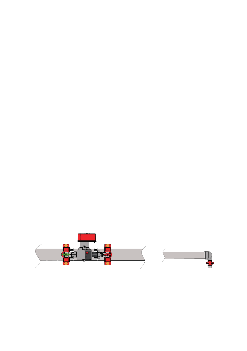
3 Marry the Zonecheck 450 Retro-fit up to the pipe around the flow-switch to make sure it
will fit on facing the correct direction and in the correct orientation (page 05).
4. Measure the distance between the mech-tee outlets.
5. On the centre-line of the pipe mark two points equally spaced either side of the existing
flow-switch using the measurement you have just taken (this should be around 313mm
or 12 3/8” - see page 10 for details).
6. Cut two holes on the designated marks with a hole-saw:
2”-4”pipe ...............
6” pipe ....................
8” pipe.....................
7. Remove burrs and clean pipe surface around the hole.
8. Fit the Zonecheck to the pipe. Double check it is facing the correct direction & in the
correct orientation (see pages 04 & 05) before tightening the mech-tee bolts.
9. Note the direction of sprinkler system flow and apply the two flow-arrow labels (provided)
to the pipe either side of flow-switch.
10. Fit the key-switch to the wall in a suitable location that is easy to reach from floor level.
11. Wire the Zonecheck & flow-switch in accordance with the instructions on pages 07-09.
12. Re-charge the zone with water (on completion, proceed to commissioning - page 03).
Ø38mm (1½” hole-saw)
Ø51mm (2” hole-saw)
Ø64mm (2½” hole-saw)
3
Commissioning
1 Contact the responsible person to authorise a flow-switch test.
2 Ensure the Zonecheck red and green valves are both open.
3 Ensure pipework is fully vented using suitable vent valve
4 Connect a hosepipe to the test-valve at the furthest point on the zone.
5 Contract building management to authorise a flow-switch test.
6 Discharge water through the hose (this is a once only commissioning test).
7 Check that the WATER FLOW green LED is illuminated on the key-switch.
8 Close the test valve.
9 Turn the Zonecheck Key-switch to SELF TEST and check the PUMP RUNNING and
FLOW-SWITCH ACTIVATED LEDs are illuminated (this could take up to 30 seconds).
10 Confirm with the responsible person that they have received their test signal.
11 Turn the Key-switch key to STANDBY.
12 If zone valve is wired to key-switch, check function of VALVE FAULT LED on the key-
switch, which should illuminate when valve is not in the fully open position.
13 Fix operating instructions to wall, preferably next to the key-switch. Also place the
Zonecheck Isolation valve location sticker in a suitable position to let others know
where the unit is.
14 Ensure that the end user is instructed on how to carry out a routine test and explain
procedure for when VALVE FAULT LED is illuminated.
15 Fill in & hand over a completion certificate. Make sure that the responsible person has
been made aware that the system is back online.

4
Testing
Test one Zonecheck
1 Insert the key into the key-switch and turn to SELF TEST (the pump light will activate).
2 When the flow-switch operates, the WATER FLOW light will activate (please wait for
up to 30 seconds for the flow-switch to operate).
3 Return to STANDBY position and remove the key.
Test a group of Zonechecks
1 To test all the Zonechecks in the group, insert the key into the key-switch and turn to
GROUP TEST.
2 Look at the central fire control panel to confirm simultaneous activation of all the flow-
switches within the group.
3 Return to STANDBY position and remove the key.
FLOW-SWITCH
ACTIVATED
GROUP
TEST
SELF
TEST
STANDBY
PUMP
RUNNING
VALVE
FAULT
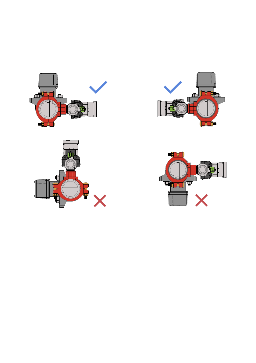
Orientation
5
• The pump direction-of-flow arrow faces the opposite direction to the system flow.
• The pump cartridge is always horizontal.
PUMP NOT HORIZONTAL
FLOW-SWITCH ON UNDERSIDE OF PIPE
6
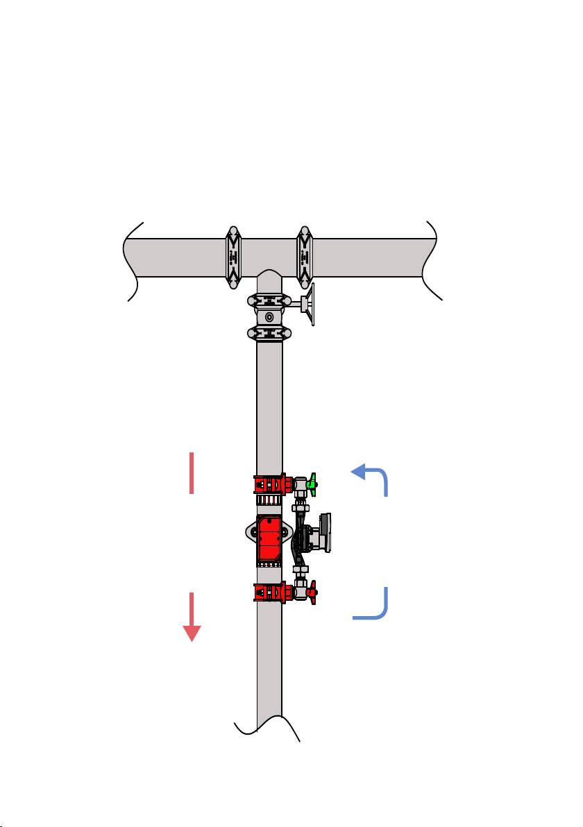
Typical Connection
A typical multi-occupancy Zonecheck Installation. For an example of a typical riser
installation visit our website at www.projectfire.co.uk.
Zonevalve
(view from above)
System Flow
Pump Flow

Please note Zonecheck should be installed by a competent fire sprinkler installer and wired
up by a qualified electrician.
Stand Alone Wiring
7
WIELAN
CONNECTORS
(SUPPLIED)
ZONECHECK
PUMP
2
2
1+-
COM N/O
COM
1 2
N/O
1
G
NL
N
L
3A
Switched
Fused Spur
Power
Supply
G
Fire Alarm/
Interface
Device
Flow-switch
Key-switch
Grouping
Monitored Zone/
Isolation Valve
(Optional)

8
Your Zonecheck will come with male/female connectors which are connected to the pump.
Simply remove the free (female) side of the connector by using a terminal screwdriver (A).
Remove the cover from the connector using a PH1 screwdriver to expose the terminals
(B). Then wire from the key-switch to the connector ensuring that the wiring matches the
symbols on the connector. Finally, press the two connectors together again until they click/
lock together.
Additional Wiring Guidance
A
B
Male Connector
(pre-wired to Zonecheck pump)
Female Connector
(to be wired to key-switch)
9
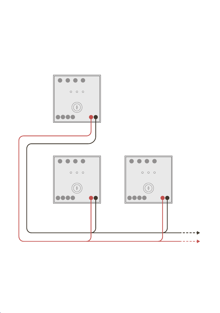
Upto 25 Zonechecks can be tested simultaneously when the Zonecheck units are wired in
parallel via interconnect by turning the master key-switch to GROUP TEST. The maximum
cable distance of 300m should not be exceeded when grouping key-switches.
Group Wiring
2
2
1+-
1
NL
N
L
2
2
1+-
1
NL
N
L
2
2
1+-
1
NL
N
L
KEY-SWITCH 02KEY-SWITCH 01
MASTER KEY-SWITCH
Zonecheck should be installed by a competent fire sprinkler installer and wired up by a
qualified electrician.
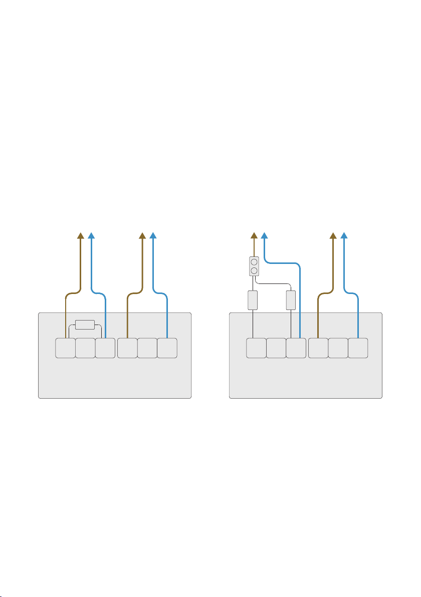
The following diagrams show typical fire-alarm/interface connections for flow-switch end-
of-line resistors. The wiring setup depends on the make and model of the fire panel used.
Always refer to your specific fire-alarm panel instructions for more information.
Flow-switch Wiring
COM NC NO NC
SWITCH 1 SWITCH 2
470 Ω
COM NO
FLOW-SWITCH
FIRE-ALARM
PANEL/INTERFACE KEY-SWITCH
COM NC NO NC
SWITCH 1 SWITCH 2
COM NO
FLOW-SWITCH
FIRE-ALARM
PANEL/INTERFACE KEY-SWITCH
470 Ω
1 Ω
DIAGRAMS SHOW TYPICAL APPLICATIONS ONLY.
ALWAYS REFER TO FIRE-ALARM INSTRUCTIONS.
10

Dimensions
Please check your version of flow-switch (System Sensor or Potter) before referring to
dimensions.
A
BC
CLEAR
SPACE
160 D
Hole locations
Model
ZC450-R50
ZC450-R65
ZC450-R80
ZC450-R100
2”
2½”
3”
4”
A
45
52
56
72
B
210
128
222
232
C
395
395
395
416
D
1.7”
2”
2.2”
2.8”
8.3”
5.0”
8.7”
9.1”
15.6”
15.6”
15.6”
16.4”
50
65
80
100
=
313
=
±2*
(12.638”)
* Due to assembly with screwed threads, exact
dimension will vary slightly. If in doubt, measure
hole centres on product before drilling.
130
150
162
195
5.2”
5.9”
6.4”
7.5”
Model
ZC450-R150
ZC450-R200
6”
8”
Ø (nominal) A
98
120
B
346
398
C
418
425
D
3.9”
4.7”
13.6”
15.7”
16.5”
16.7”
150
200
* Due to assembly with screwed threads, exact
dimension will vary slightly. If in doubt, measure
hole centres on product before drilling.
258
330
10.1”
13”
Ø (nominal)
Model
ZC450-R50
ZC450-R65
ZC450-R80
ZC450-R100
2”
2½”
3”
4”
A
45
52
56
72
B
210
128
222
232
C
395
395
395
416
D
1.7”
2”
2.2”
2.8”
8.3”
5.0”
8.7”
9.1”
15.6”
15.6”
15.6”
16.4”
50
65
80
100
=
313
=
±2*
(12.638”)
* Due to assembly with screwed threads, exact
dimension will vary slightly. If in doubt, measure
hole centres on product before drilling.
130
150
162
195
5.2”
5.9”
6.4”
7.5”
Model
ZC450-R150
ZC450-R200
6”
8”
Ø (nominal) A
98
120
B
346
398
C
418
425
D
3.9”
4.7”
13.6”
15.7”
16.5”
16.7”
150
200
* Due to assembly with screwed threads, exact
dimension will vary slightly. If in doubt, measure
hole centres on product before drilling.
258
330
10.1”
13”
Ø (nominal)
11

12
Specifications
Zonecheck
Working Pressure Rating Water, 12 bar (175 psi) maximum
Operating Temperature Range 0°C - 49°C (32°F – 120°F)
Pipe Diameter 50, 65, 80, 100, 150 & 200 mm (2, 2½ 3, 4, 6 & 8“)
Approvals LPCB, UL, FM and VdS
Circulation Pump
Operating Voltage 1~230v 50Hz
Full Load Current 0.66 A
Power Rating 75 W maximum
IP Rating IPX4D
Key-switch
Mounting Flush-mounting
Type ZCKSE
Operating Voltage Single-phase 220 V, 50 Hz
Internal consumption 7.5 W maximum
Operation Modes Self test: Wired locally
Group test: Interconnected
Standby (Ready State) No LED
Test Initiation ‘Pump’ LED
Flow-switch Activation ‘Water Flow’ LED

Troubleshooting
Zonecheck should be troubleshooted by a competent fire sprinkler installer and wiring
checked by a qualified electrician.
No lights on key-switch Isolate the power then check the Key-switch wiring
against the wiring diagram. Confirm the power supply
has been connected properly.
Only PUMP RUNNING LED
illuminates.
Check the red & green Zonecheck valves are open.
1 Check Zonecheck has been installed facing the
correct way.
2 Remove the plastic lid from the flow-switch,
push and hold the trigger with your finger for 30
seconds. If the Flow Switch Activated LED (on the
key-switch) operates see below. If not check the
wiring against the diagram.
Pump runs hot & does not
operate the flow-switch.
Pump is airlocked.
Vent air from pipework using appropriate vent/valve
(not included) and repeat test.
It may take some time to fully remove the air from the
pump impeller.
Pump runs while in STANDBY. Key-switch has been incorrectly wired. Isolate the
power then check the wiring diagram and rewire.
If there is still a problem, contact technical support at
Project Fire.
13

14
Important Information
• Zonecheck Retrofit should be installed by a competent fire sprinkler installer and wired
up by a qualified electrician.
• Ensure Zonecheck Retrofit is installed both mechanically and electrically
commissioned and tested prior to leaving site.
• Ensure protection to Zonecheck is employed whenever there is an extended period
from installation to commissioning.
• If the Zonecheck Retrofit could be activated when the sprinkler system zone is drained
down then it is vitally important that the Zonecheck red and green valves are left in the
closed position. This is to ensure the motor is not accidentally run dry and damaged.
(Please ensure the commissioning engineer is aware of the closed Zonecheck valve
status).
• Always use a flat faced wrench for Zonecheck commissioning.
• The suggested location for the key-switch is at low level for visibility and access.
• The suggested location for Master key-switch (optional, see group testing) is adjacent
to the fire alarm panel.
• Fix operating instructions to wall, preferably next to key-switch.
• Each Zonecheck Retrofit is factory assembled and tested. Do not attempt to
reconfigure. Tampering will void the warranty.
• Maximum working pressure - 12 bar (175 psi), test pressure - 18 bar (260 psi).
• Use Zonecheck flow-switch testers in wet-pipe systems only. Do not use in dry pipe,
deluge, or pre-action systems.
• Only activate the Zonecheck key-switch when the valves are opened and the sprinkler
system is full.
• The pump direction-of-flow arrow faces the opposite direction to the system flow.
• A local monitored zone/isolation valve can be wired to the key-switch for added
functionality. If connected, when the valve is not in the fully open position the key-
switch ‘VALVE FAULT’ LED will illuminate.

Standards & Approvals
In the majority of multi-occupancy sprinklered premises it is a requirement of BS EN
12845 that each tenant should carry out a functional test on a fitted flow-switch every
quarter. All international fire code standards such as NFPA etc all make the flow-switch test
mandatory. Zonecheck can carry out this test at the turn of a key. Zonecheck is approved by
LPCB, UL, FM and VdS.
15
Responsible Disposal
Project Fire recommend that the product needs to be disposed of correctly when the
product reaches the end of its life cycle.
Disposal of business or commercial waste should be in compliance and accordance with
government guidance and regulations.
Disposal of electrical waste should be in compliance and accordance with “Waste Electrical
and Electronic Equipment recycling” (WEEE).

16
One Year Warranty
Project Fire Products warrants its enclosed Zonecheck flow-switch tester to be free from
defects in materials and workmanship under normal use and service for a period of one
year from date of manufacture. Project Fire Products makes no other express warranty
for this flow-switch tester. No agent, representative, dealer or employee of the Company
has the authority to increase or alter the obligations or limitations of this warranty. The
Company’s obligation of this warranty shall be limited to the repair or replacement of any
part of the flow switch tester, which is found to be defective in materials or workmanship
under normal use and service during the one-year period commencing with the date of
manufacture. After phoning Project Fire’s number, 01889 271 271 for a Return Authorization
number, send defective units postage prepaid to Project Fire, Pasturefields Industrial
Estate, Pasturefields Lane, Hixon, Stas, ST18 0PH. Please include a note describing the
malfunction and suspected cause of failure. The Company shall not be obligated to repair
or replace units, which are found to be defective because of damage, unreasonable use,
modifications, or alterations occurring after the date of manufacture. In no case shall the
Company be liable for any consequential or incidental damages for breach of this or any
other Warranty, expressed or implied whatsoever, even if the loss or damage is caused by
the Company’s negligence or fault.
End of Life Cycle
Project Fire recommend that at the end of the products life cycle the items need to be
disposed of correctly:
Disposal of business or commercial waste should be in compliance and accordance with
government guidance and regulations.
Disposal of electrical waste should be in compliance and accordance with “Waste Electrical
and Electronic Equipment recycling” (WEEE)

Project Fire Products Ltd
Pasturefields Lane
Hixon, Staordshire
ST18 0PH, UK
+44 (0)1889 271271
support@projectfire.co.uk
www.projectfire.co.uk
This manual suits for next models
3
Table of contents
Other Project Fire Test Equipment manuals


