HDL Buspro User manual

Buspro Wireless: Pairing_of Buspro Wireless_devices
1 z 6
M_Pairing_of _Buspro_Wireless_devices_(2019-11)_EN
Buspro Wireless
Pairing devices to the wireless
network
Description of procedure and settings
v. 2019/11/7
© HDL Automation s.r.o. JU

Buspro Wireless: Pairing_of Buspro Wireless_devices
2 z 6
M_Pairing_of _Buspro_Wireless_devices_(2019-11)_EN
Obsah
1. General ...................................................................................................................3
2. Setup procedure......................................................................................................3
2.1. Connecting the wireless gateway to the computer.........................................................3
Ethernet setup..................................................................................................................3
2.2. Network parameters setup..............................................................................................4
Search and load the Buspro Wireless IP gateway ............................................................4
Setting up the wireless network address system.............................................................4
Setting the transmission parameters of the wireless network ........................................4
2.3. Pairing devices .................................................................................................................5
Switch the gateway to pairing mode................................................................................5
Pairing wireless devices with the gateway.......................................................................5
2.4. Setting devices .................................................................................................................6

Buspro Wireless: Pairing_of Buspro Wireless_devices
3 z 6
M_Pairing_of _Buspro_Wireless_devices_(2019-11)_EN
1. General
Buspro Wireless is part of the Buspro system, the devices of which communicate with each
other via a cable bus. Wireless devices do not require a cable bus, but communicate
wirelessly in a dedicated frequency band. This results in a difference in commissioning the
system. The wireless devices must first be connected to a common wireless network, then
the further settings are identical to the settings of the Buspro devices with a cable bus.
The parameters are set using the HBST2 program running on a computer, which is
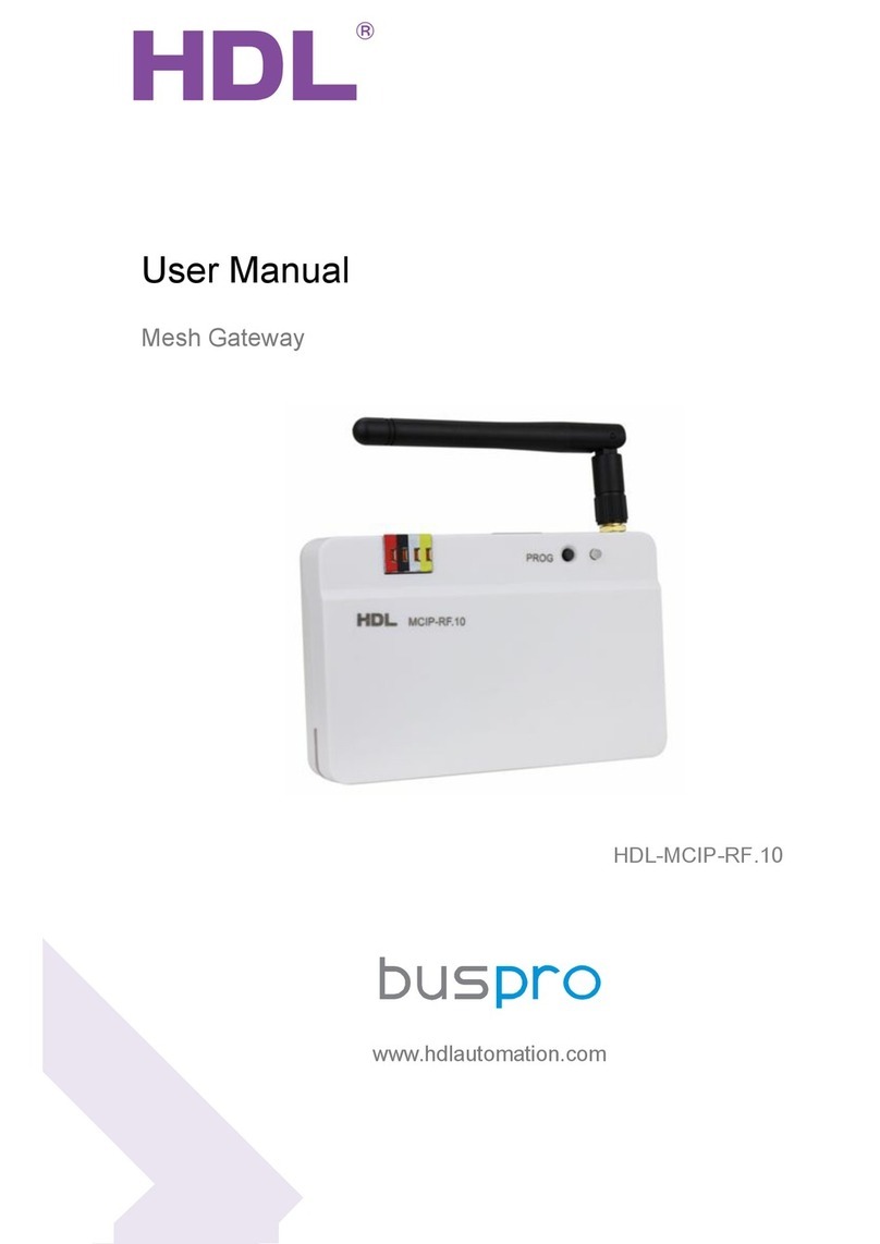
connected to the wireless network via the HDL-MCIP-RF02.10 gateway using Ethernet, see
Fig. 1. This gateway has both an Ethernet connection to the computer and an antenna that
is connected to the wireless networks.
Note: After setting up the entire network, the gateway can be disconnected. However, the
gateway must be left plugged in permanently if a permanent wireless Ethernet connection is
required, e.g. for Internet connectivity.
This gateway can also ensure the connection of the wireless network with the Buspro cable
bus.
2. Setup procedure
2.1.Connecting the wireless gateway to the computer
Connect a personal computer with OS Windows 7, 8, 10 to the wireless gateway, e.g.
according to Fig. 1. The connection can also be made via a router.
Ethernet setup
The IP address of the HDL-MCIP-RF02.10 gateway is factory set to 192.168.10.250. If your
gateway has a different IP address (unknown to you), factory settings can be restored by
pressing the PROG button for 10-15 seconds.
For a direct connection according to Fig. 1, a fixed address of 192.168.10.200 must be set
on the computer's Ethernet adapter (instead of 200, it can be a different value from 3 to 254
other than 250).
If a IP router or switch is used for connection, it must have a network set to the
192.168.10.x range. The computer's Ethernet adapter can then be set to DHCP mode.
Ethernet
Buspro
Fig.1 Wireless gateway HDL-MCIP-RF02.10 and their connection to the PC
ethernet

Buspro Wireless: Pairing_of Buspro Wireless_devices
4 z 6
M_Pairing_of _Buspro_Wireless_devices_(2019-11)_EN
2.2.Network parameters setup
Search and load the Buspro Wireless IP gateway
Network parameters are set by setting the HDL-MCIP-RF02.10 gateway. The gateway must
first be loaded to appear in the basic screen of the HBST2 program, see Fig.2.
Setting up the wireless network address system
After loading the gateway, select the address system of the Buspro Wireless network. The
address consists of two parts, Subnet ID and Device ID, see Fig. 2. Select the value of the
Subnet ID parameter, the factory setting is usually 200, values from 1 to 255 can be used.
Change the address by clicking on the gateway line in the Subnet ID column or Device ID.
Note: Unlike other devices, the Device ID address value of the wireless gateway cannot be
changed and is 0.
Setting the transmission parameters of the wireless network
Settings are made in the gateway's basic window, which is opened by clicking on the
gateway row in the Model or
Description column. Set the
parameters according to Fig. 3
and 4.
Fig.2 Wireless gateway HDL-MCIP-RF02.10 and its connection to the PC
The Fast search command starts the search of
devices. The result is a single find at the
moment, and that is the MCIP wireless gateway.
Fig.3 Setting the wireless network transmission parameters, tab Basic setup
Na závěr nezapomeňte
nastavení uložit.
Band: frequency band.
Choose SRD to operate
the system in Europe.
Channel: Choose the frequency so
as not to interfere with any other
devices.
Note
Multiple wireless networks
operating in the same space can be
separated by different frequencies.
Password: Choose a password to
encrypt your network. Max. length 16
characters.

Buspro Wireless: Pairing_of Buspro Wireless_devices
5 z 6
M_Pairing_of _Buspro_Wireless_devices_(2019-11)_EN
Fig.5 Introducing the HDL-MCIP-RF02.10 Wireless
Gateway into setting mode
The setting mode
is indicated by a
fast flashing of
the red light next
to the
MODE
inscription.
The gateway is put
into setting mode by
pressing the
Prog
button three times
2.3.Pairing devices
Switch the gateway to pairing mode
Before pairing, make sure the
wireless gateway has been set
up according to the previous
steps.
Then put the gateway into the
setup mode by pressing the
Prog button three times, see
Fig. 5, or by clicking the Start
setup button, see Fig. 3. The
setup mode is indicated by a
rapid flashing of the red light,
see Fig. 5.
Note: If the gateway is in setup
mode, it cannot be loaded into
the HBST2 program. After
matching the desired devices,
do not forget to cancel the
pairing mode. This is done by
simply pressing the Prog
button.
Pairing wireless devices with the gateway
Only one device can be paired with the gateway at a time, so the pairing of multiple devices
is done sequentially. The device to be paired must also (like a gateway) be set to pairing
mode. This is done as follows:
If the device has a "programming button" such as a wireless relay, etc., this button is
pressed three times in rapid succession, causing the device's light to flash rapidly at 2 Hz
Fig.4 Setting the transmission parameters of the wireless network, tab Filter RJ45 ->485
Network style: set the Mesh option.
Note
When choosing Bridge, the
gateway ensures the backbone
network, i.e. the transmission between
several different segments.
Buspro port Subnet: specifies the value of the Buspro cable
bus segment that can be connected to the wireless
gateway. The gateway ensures the cooperation of the bus
and the cable network. This parameter does not matter
when the wireless network is operating separately.

Buspro Wireless: Pairing_of Buspro Wireless_devices
6 z 6
M_Pairing_of _Buspro_Wireless_devices_(2019-11)_EN
(usually green). The light blinks rapidly until pairing is complete. When the indicator light
goes to slow flashing once every 2 seconds, the device is paired and automatically
switched to normal working mode.
Controllers that do not have a programming button are put into pairing mode by pressing a
certain combination of buttons (control panels), or by pressing the button for a long time, or
by connecting under voltage when the button was previously pressed. For details, see the
manual Introduction to the HDL Wireless System, or in the case of newer types, this
information is given in the catalog sheet of the device. The most common types of drivers
are set as follows:
• DLP Panel: Press the 1st and 8th buttons at the same time to bring up the menu. Select
the WIRELESS option in the menu. This will illuminate the LEDs of buttons 1 and 8 to
indicate that the panel is ready to pair. After successful pairing, the lights will turn off.
• Other types of panels: press any button for 25 seconds, which will flash the backlight of
the buttons to indicate that the panel is ready for pairing.
Note: New devices that have not yet been paired are set to pairing mode automatically
when connected to power.
Note: The ideal distance between the gate and the device to be paired is about 0.5 to 2
meters, i.e. on the table, before mounting the device in its construction position. However,
under normal conditions, pairing should work at full radio range, i.e. up to 20m.
2.4.Setting devices
The devices paired with the wireless gateway are further set up in the same way as the
Buspro devices connected to the cable bus, i.e. using the HBST2 program. Other principles
are also the same, i.e. all devices of the wireless network must have the same Subnet ID
value as the one that was set on the wireless gateway, i.e. usually 200, see section 2.2.
Table of contents
Other HDL Gateway manuals