Telco GW-482S User manual

MN100143 Rev B
EdgeGate 482S
VoIP Gateway
(GW-482S)
Installation Guide

GW-482S INSTALLATION GUID E
ii MN100143 Rev B
CERTIFICATION
Telco Systems certifies that this product met its published specifications at the time of shipment
from thefactory.
Copyright © Telco Systems, Ltd., 2005. All rights reserved. All trademarks are property of their
respective owners. No part of this documentation may be reproduced in any form or by any means
or used to make any derivative work (such as translation, transformation, or adaptation) without
permission from Telco Systems, Ltd.
Specificationsare subject to change without priornotice.

GW-482S INSTALLATION GUID E
iii MN100143 Rev B
Revision History
Revision Date Description
New October 2005 Created
B December 2005 Added supportfor GW-482S-LV-2-G and GW-482S-LV-4-G
GW-482S INSTALLATION GUID E
iv MN100143 Rev B
SAFETY CONSIDERATIONS
Please read these safety considerations before you begin installation. The instructions in this guide
are for use by qualifiedpersonnel only. To avoid shock, do not perform any procedures other than
those contained in the inst ructions.
EL ECTRIC SHOCK PREVENTION
Disconnect the product from the power line before removing the cover. Any adjustment and
maintenance of the opened device should be done only while the device is disconnected from its
source of power and should only beperformed by qualified personnel, authorized by Telco.
GROUNDING
Before connecting the product to the power line, make sure that the protective ground terminal of
thedevice isconnectedto the ground by astandard groundingconductor.
Any interruption of the protective (grounding) conductor or disconnection of the protective ground
terminal can makethe device unsafeto use. Intentional interruption is prohibited.
FUSES
Make sure that only UL recognized or listed fuses with the specified current rating and model
number or equivalent types are used for replacement. The use of repaired fuses and the short-
circuitingoffuseholdersisprohibited.
For all fuses, use 4A, 5mm x 20mm glass fuses, manufactured by Schurter, model 0034.3123, rated
250 V AC,or equivalent UL approved DC rated fuse.
LINEVOLTAGE
Before connecting the product to the power line, make sure the voltage of the power source
matches the requirements of the product, as marked on the label located near thepower connector.

vMN100143 Rev B
Table of Contents
INTRODUCTION............................................................................................................. 1
HOW TO GET HELP........................................................................................................... 1
BEFORE YOU INSTALL ...................................................................................................... 2
INSTALLING THE GW-482S............................................................................................ 5
MOUNTING THE CABINET.................................................................................................. 5
CONNECTING THE CABINET TOTHE GROUND......................................................................... 6
FIBEROPTICCABLE CONNECTION....................................................................................... 7
POWER CABLECONNECTION.............................................................................................. 8
CONNECTING THE ACPOWERCABLE................................................................................... 9
INSTALLING THEBATTERY................................................................................................10
CONNECTING ETHERNET AND PHONE CABLES.........................................................12
INSTALLATION INSTRUCTIONS FOR A UNIT SUPP LIED WITHOUT APATCH PANEL..........................12
INSTALLATION INSTRUCTIONS FOR UNIT SUPPLIEDWITHPATCH PANEL.....................................14
DIAGNOSTICS...............................................................................................................17
GATEWAY DIAGNOSTICS..................................................................................................17
SFP LINK ACTIVITY ........................................................................................................17
BATTERY CHARGER DIAGNOSTICS .....................................................................................18
SPECIFICATIONS..........................................................................................................19
APPENDIX A PATCH PANEL KIT INSTALLATION....................................................20
REQUIRED EQUIPMENT.....................................................................................................20
INSTALLATIONPROCEDURE ..............................................................................................20
APPENDIX B CABLE PINOUTS..................................................................................23

1MN100143 Rev B
Introduction
This guide provides installation instructions for the GW-482S family of VoIP Gateway systems.
The GW-482S is comprised of a VoIP gateway board, a battery backup and an AC/DC adaptor in
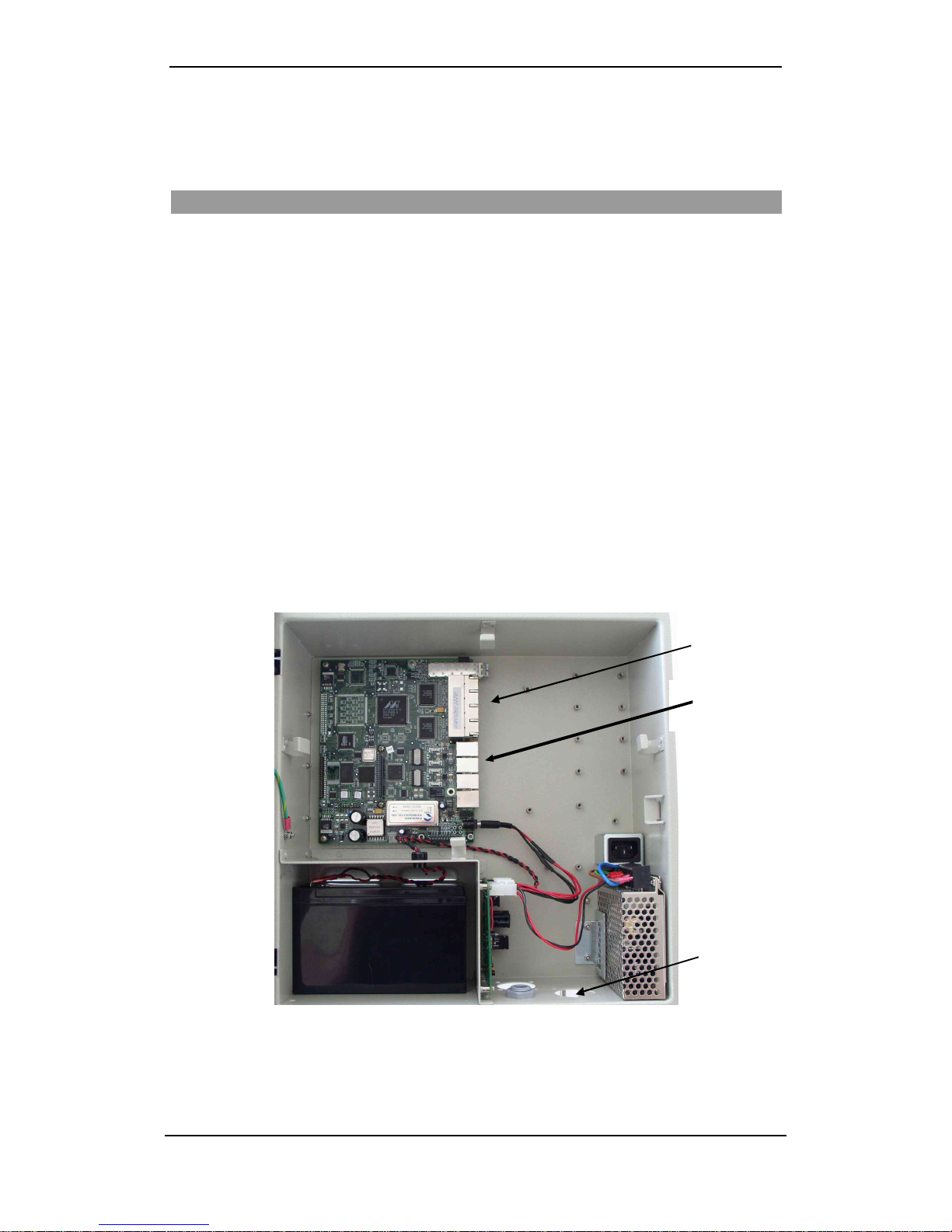
an outdoor cabinet. Figure1 shows the main components of the GW-482S system.
After completingthe installation, refer to EdgeGate VoIP Gateway H.323, MGCP, SIP User Guide
(MN100112)to configurethe EdgeGate VoIP Gateway system.
How to Get Help
Telco Systems ensures that the quality technical support you have come to expect for your Telco
productswill be maintained.
•Web Access
http://www.telco.com
•E-mail Access
E-mail your inquiry to: support@batm.co.il
•Telephone Access
Telco Systems Tech Support Hotline
800-227-0937 (U.S. and Canada)
GW-482S INSTALLATION GUID E
2MN100143 Rev B
Before You Install
Before you begin installation:
1.Please reviewthe packing list.
2. Familiarizeyourself with the equipment and unit(seepicturesbelow).
Packing List
•GW-482S Cabinet wit h EdgeGat e 482S VoIP Gateway Board.
•110/220 VAC/DCAdaptor + ACpower cable (not includedwith GW-482S-LV-X-G).
•Two wall mounting bars.
•Cardboard mountingtemplate.
•Set of four NF10-32 nuts, flat washers and spring washers.
•Set of flanges and Neoprenegaskets for attaching various diameter cable conduits.
•Set of accessories for attaching and positioning wires.
•EdgeGate consolecable.
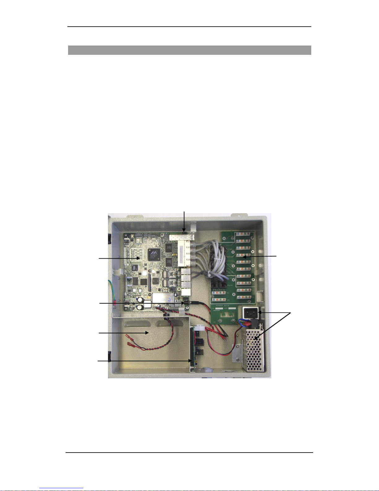
Figure1:The GW-482S MainComponents
VoIP Gateway
Board
SFPTransceiver
Cage
LAN and
Phone Patch
Charger
Board
Battery
Compartment
110/220 AC/DC
Adapter and AC
Plug
DC Power Input for
GW-482-LVUnits
GW-482S INSTALLATION GUID E
3MN100143 Rev B
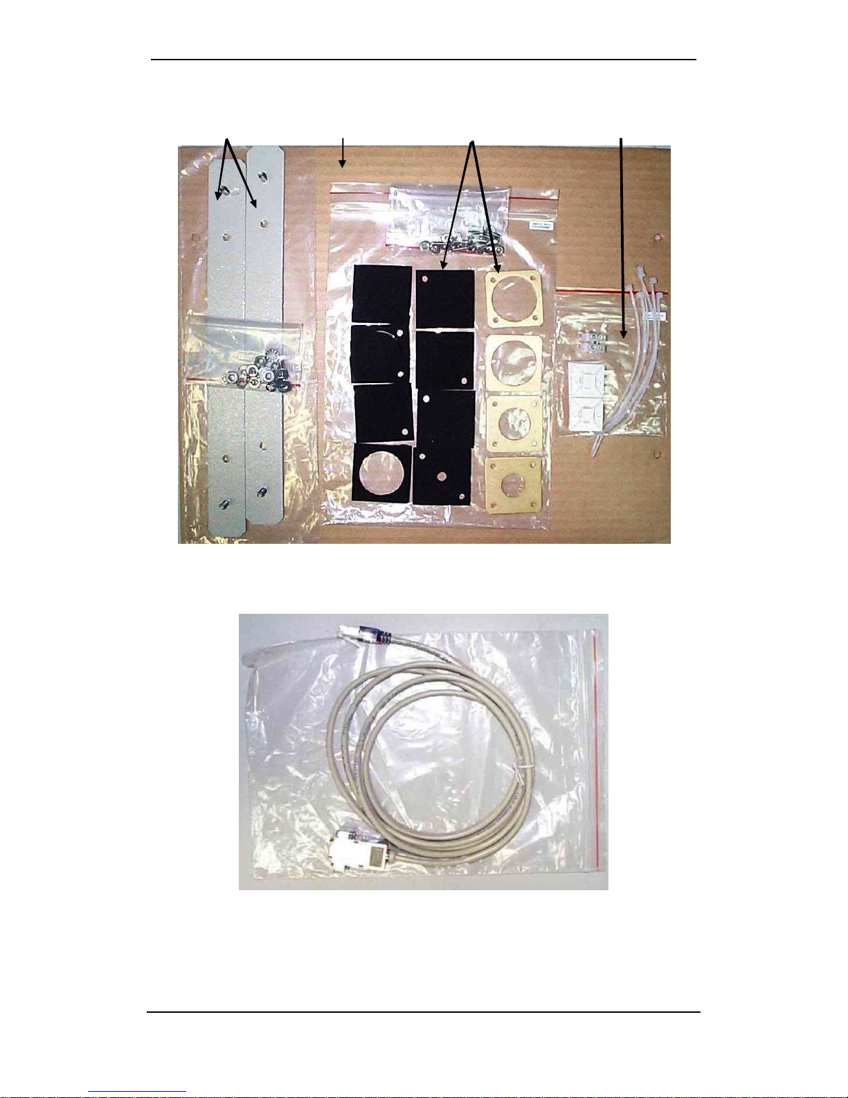
Figure 2: Mounting Bars and Accessories
Figure3:ConsoleCable
Mounting
bar
s
Flanges and Neoprene
gaskets Accessories forattaching
and positioning wires
Cardboard
mounting template

GW-482S INSTALLATION GUID E
4MN100143 Rev B
Console Grounding
The RS-232 cable must be connectedto a floating PC, i.e. laptop, to prevent
the unit from being permanently damaged.
NOTE
The console cable is provided for use by service personnel for configuring
the EdgeGate 482S VoIP Gateway, as described in theEdgeGate VoIP
Gateway H.323, MGCP, SIP User Guide (DocumentMN100112).
Figure 4: AC Connector (plug)
GW-482S INSTALLATION GUID E
5MN100143 Rev B
Installing the GW-482S
This section contains instructions for the installer. Precede according to the following installation
steps:
1. Mount the cabinet on a wall.
2. Connectthecabinet to ground.
3. Connectthefiber optic and power cables.
4. Connectthe ACpower cable.
5. Install the battery.
Mounting the Cabinet
The following items are provided for mount ing the GW-482S cabinet on a wall:
•Two mounting bars with affixed screws.
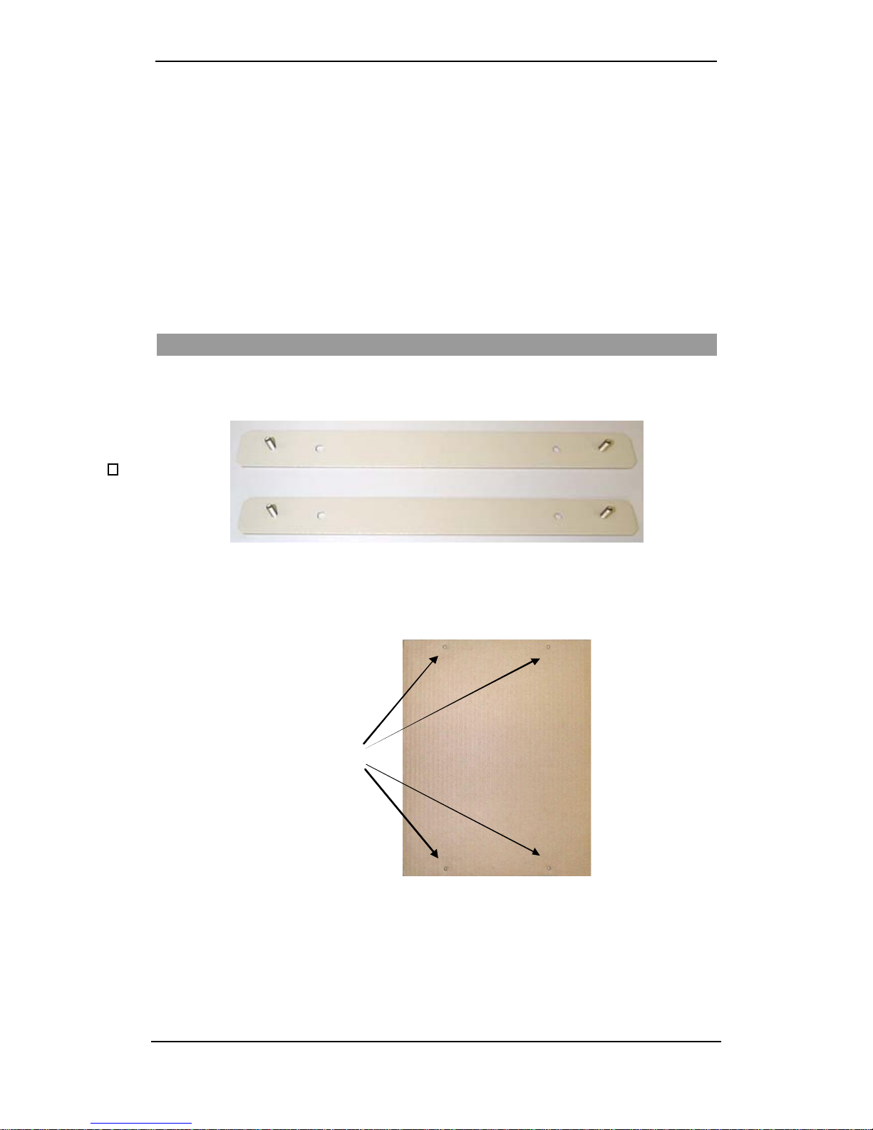
Figure5: Cabinet Mounting Bars
•A cardboard mountingtemplate (PK000195) with drill-position marks.
Depressed drill-position
marks
Figure6: Cardboard Mounting Template
To mount the cabinet on a wall:
Important –The mounting wall must be at 90 degree angle to the ground. The cabinet must be
situated with all openingsfacingthe ground.

GW-482S INSTALLATION GUID E
6MN100143 Rev B
1. Attach the mounting barsto the wall as follows:
•Place the cardboard template on the wall at the position that you want the cabinet to be.
Make surethe depressed drill-position marks are level. Use a pencilto mark the four drill-
positionsonthewall.
•Drill holes in the wall in the markedplacesandfix thetwo mounting barsfirmly in place
with suitable wall anchors and screws.
2. Hang the cabinet by its mounting bracket onto the screws on the mounting bars, and fasten
using the four NF10-32 nuts, flat washers and spring washers. Theseaccessories are
supplied in the small plastic bag inside the battery compartment. Avoid using excessive
torque (twist).
Figure7:Attaching theCabinet to the Upper Mounting Bar
Connecting the Cabinet to the Ground
Before making electrical connections to the GW-482S, you mustconnect
the cabinet to a sound and secure ground.
The grounding shall be performed in accordance with Article 810 of NEC or
Section54 of CEC.
To connect the cabinet to the ground:
•Connect the ground terminal, located underneath
the cabinet,to a reliable ground using a standard
groundingcable.
•You may also connect a grounding wire to the
other sideofthisterminal, inside the cabinet.
•Use aflat washer, a spring washer anda 7/16” nut, in that sequence, to fasten the ground lead
onthe grounding terminal. Do not apply excessive force.

GW-482S INSTALLATION GUID E
7MN100143 Rev B
Fiber Optic Cable Connection
The fiber optic transmitter is a Class 1 Laser product that may endanger
your eyes. Do not look directly into the fiber optic cables or transmitter.
NOTE
Fiber optic connectors, especially fiber edge (Ferula), must be
professionally furbishedand clean.
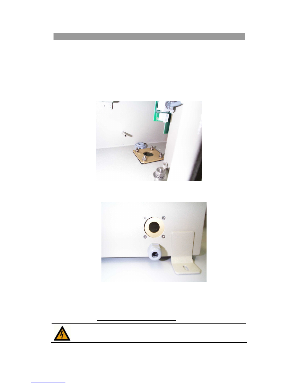
To insert the Optic Cable into the Cab inet:
1. Unscrew the cable gland at the bottom of the cabinet.
2. Push the fiber opticcable through the cable feed-thru. Tightenthe feed-thru carefully by
hand.
Figure8:Fiber OpticIngress -Insertion into Cabinet
3. Roll and fit the cable slack into thefiber optic cable holders.
Figure 9:Storing the Slack and Connecting the Fiber Optic Cable
To insert the SFP transceiver into the SFO cage:
1. Insert the Fast Ethernet SFP transceiver into the SFP cage.
2. Firmlypushthefiber intheSPFoptictransceiver.
Fiber optic
cable
SPF Cage and
Transceiver
Cable Slack
Holders
GW-482S INSTALLATION GUID E
8MN100143 Rev B
Power Cable Connection
To insert the Power Cable into the Cabine t:
1. The power cable is enclosed in a conduit. Usethe supplied flange and a Neoprene gasket
with the appropriate hole size (according to the conduit’s diameter), as follows:
•Fit the Neoprene gasket over the hole beneath the grounding terminal insidethe cabinet.
•Place the flange over the gasket and secure firmly with four screws. Use the supplied
screws,washers, spring-washersandnuts.
Figure 10:Flange and Gasket for Power CableConduit
2. Push theendof the power-cable’s conduit firmly through the gasket’s aperture.
Figure 11:Flange and Gasket, Outer View
3. Roll and fit the cable slack into the cable holders on the cabinet walls.
4. For GW-482S-LV-X connecttheBNC connector totheCon 5 connectoronthe Main
Board. Skip sections on “Connecting the ACPower Cable” and“Installingthe Battery”
and go directly to Connecting Ethernet and Phone Cables.
Do NOT plug the external power supply into the AC power at this time!
GW-482S INSTALLATION GUID E
9MN100143 Rev B
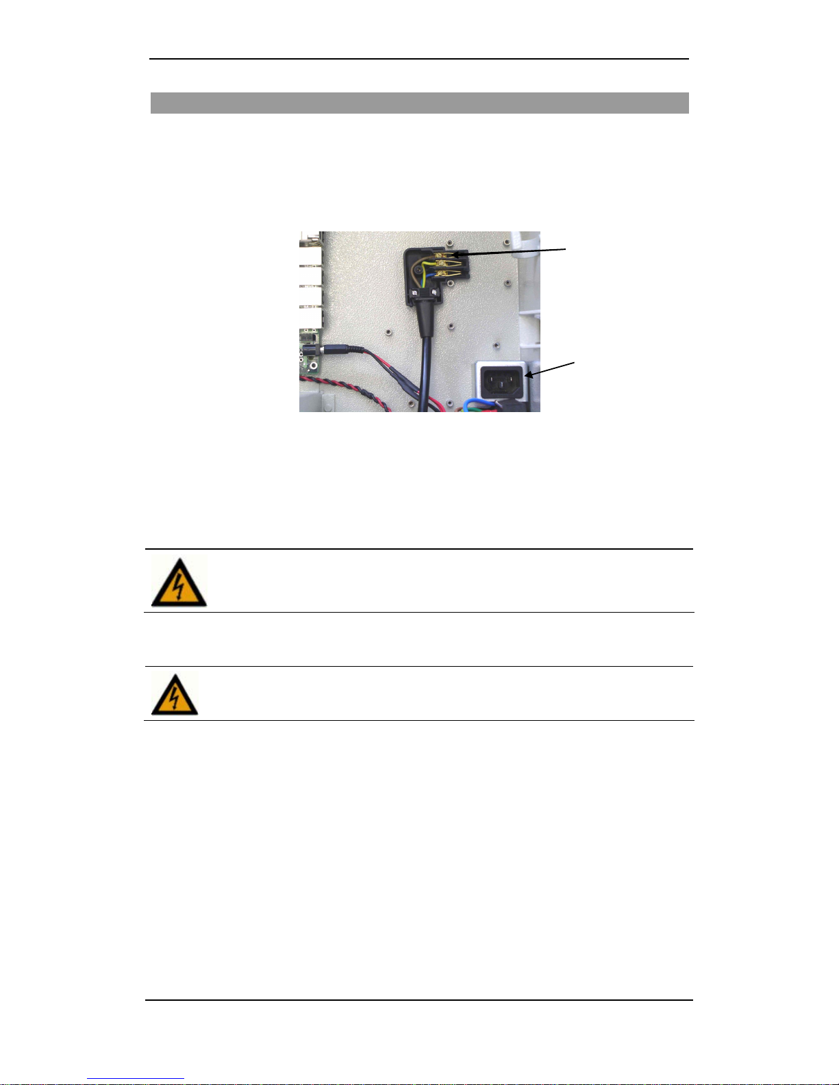
Connecting the AC Power Cable
Electric power is supplied to the unit through the AC/DC adaptor. Make sure the power cable is
insertedthrough the opening at the bottom ofthe unit.
1. After insertingthe power cable into the unit,taketheAC connector (black plug) from the
accessories andopen it.
2. Connect allthreepower cable wires to the connector’s head as shown in picture.
Figure12:PowerCable WiresConnectedintheAC Connector
3. Screwthetop oftheAC connector back on.
4. Plug the power cable into the power socket. Make sure the cable is properly plugged into
the socket.
The power source must be installed indoors.
The input power mains source is 90 - 264 VAC, 47 – 63 Hz, 0.25 A.
5. Connect cable wires to theconnector.
Do NOT plug in the power connector at this time.
Power Socket
Cable Wires
GW-482S INSTALLATION GUID E
10 MN100143 Rev B
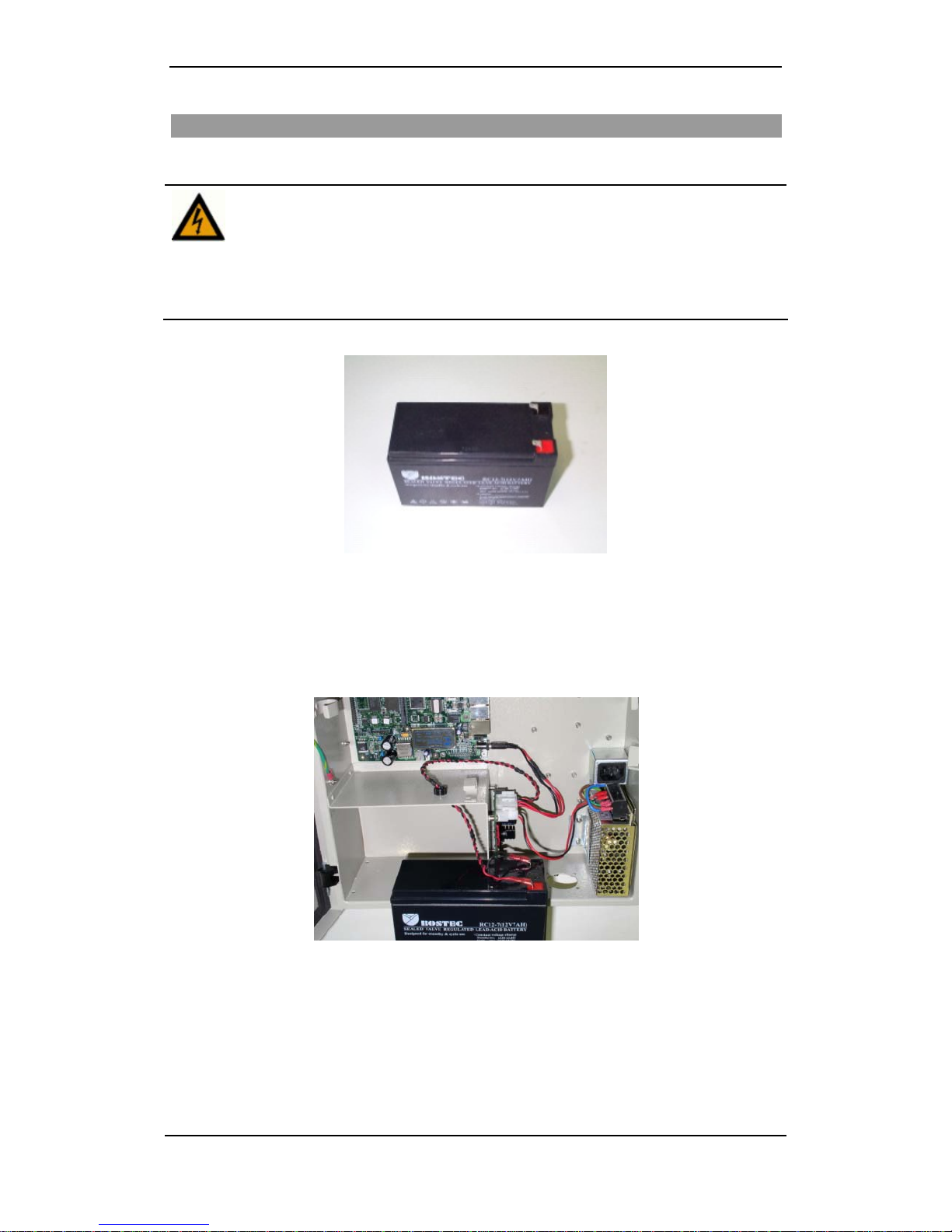
Installing the Battery
Use batterywith ¼ inch connectors.
Use onlya ULapproved battery.
Use a 12V, 7.2AH, valve regulated (sealed) lead-acid battery.
Keep the battery operating discharge temperature range between
-20° to +50° Celsius.
Keepventilation openings at the rearopen.
Figure13: ULApproved Battery
To install the battery:
1. Before insertingthe battery into its compartment, connect the BLACKwire to the MINUS
terminalonthebattery.
2. Connectthe RED wire tothePLUSterminalonthebattery.
Figure14:BatteryConnections
GW-482S INSTALLATION GUID E
11 MN100143 Rev B
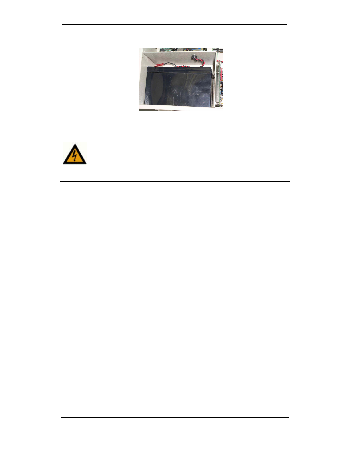
3. Placethe battery inthe battery compartment.
Figure 15:Battery in the Battery Compartment
The charger board contains a reverse-polarity-protection circuitand an
over-current protection fuse. Should a fuse blow out due to an improper or
reverse battery connection, make sure the battery is connectedproperly
and replace the fusewith a new fuse, manufactured by Schurter, model
0034.3123,4 A, 5mm x 20mm glassfuse,250 V AC or anequivalent DC
rated UL approved fuse.
GW-482S INSTALLATION GUID E
12 MN100143 Rev B
Connecting Ethernet and Phone Cables
Installation Instructions for a Unit Supplied Without a Patch Panel
The user must connect the data andvoicecommunication cablesto the Port andPhone connectors
onthegateway board.
Use the following cable types for connecting data and voice communications:
•For 10/100BaseTX ports, use shielded twisted pair 100 Ohm CAT 5 or sUTP CAT 5.
•For phones, use standard DTMFtelephone cables.
To connect the data and voice communication cables:
1. Insert the cablesthrough the ingress at the bottom of the unit. Push the cables in, one at a
time, through the small opening in the center of the rubber seal.
2. ConnecttheEthernet RJ-45 connectorstothe10/100BaseT/TX connectors ofthe
customers’ work-stations using a straight-through CAT 5 Ethernet cable.
3. Connect DTMFtelephonesto the RJ-11 connectors. Upto 5 phonescan be connectedin
parallel to each RJ-11 connector.
4. Plug in theAC connector.
Figure16: LAN and PHONE Connectors onthe GatewayBoard
LAN Ports
Voice
Connectors
Ingress
GW-482S INSTALLATION GUID E
13 MN100143 Rev B
NOTE
If you need to install the Patch Panel Kit, refer to Appendix A.
Client-Side Connectors
Connector Description
LAN Ports Eight (8) 10/100BaseT/TX portswith RJ-45 connectors.
(For GW-482S-x-F,TX port#8 isnot active if FOport isselected).
Connect computersto theseportsusing straight-throughcables, or
anyother 10/100BaseT/TXcompatible devicesusing appropriate
cables.
FO LAN Port One (1)fiberopticport.
Phone Two RJ-11 connectors. Telephone portslines1 and2 connect to
standardanalog DTMF telephonesand accessories. (For GW-482S-
4-x there are 2 additional (piggyback) RJ-11 connectors.)
Pinsactuallyused: the two central pins(No. 2 and3infour-pins
connectorsor 3and 4 in six-pin connectors).
•Insert usercables directly into the user’s house.Do not run cables
beyond 140 feet outdoors!
•Cables may NOTbe connectedto TNV (Telecommunication Network
Voltages).
•Do not connect any port or cable from/to the telephone network!
GW-482S INSTALLATION GUID E
14 MN100143 Rev B
Installation Instructions for Unit Supplied With Patch Panel
RequiredEquipment
•Type-110 insertiontool
•Screwdriver
•Recommended cables:
For 10/100BaseTXLANports connections, use shieldedtwisted pair100 Ohm CAT
5, also called STP CAT 5 with a solid wire.
For phone connections, use standardtelephone with solid wires
Connecting the Ethernet and DTMF Phone Cables
•The user must connect the data and voice communication cables to the
LAN and Phone connectors on the Patch Panel usinga Type-110 insertion
tool).
•For 10/100BaseTX ports, use shielded twisted pair 100 Ohm CAT5 or STP
CAT5 with solidwire.
•For phones, use standard DTMF telephone cables.
1. Push up to eight (8) 10/100BaseTX wires and the phone wires through the ingress at th
e
bottom of the unit. Push the cables in, one at a time, through the small opening in the center o
f
the rubber seal.
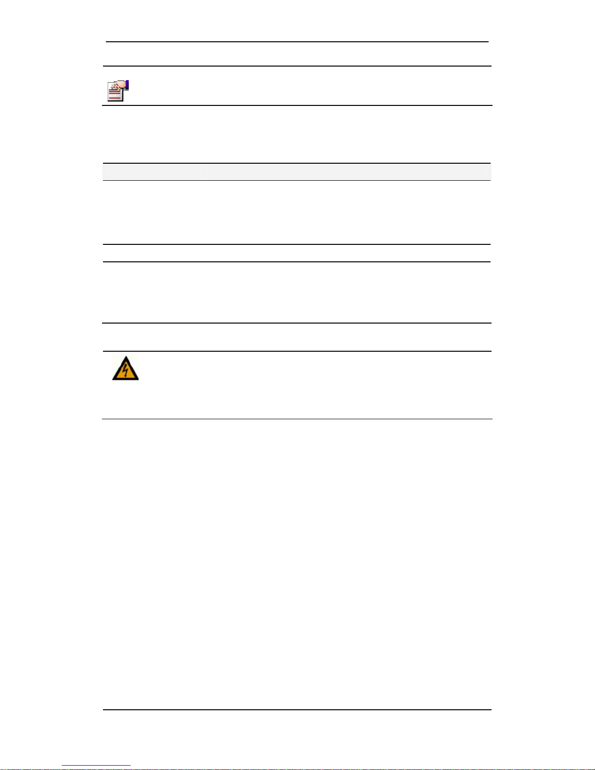
Figure 17: The LAN port and Phone Connectors on the Patch Panel
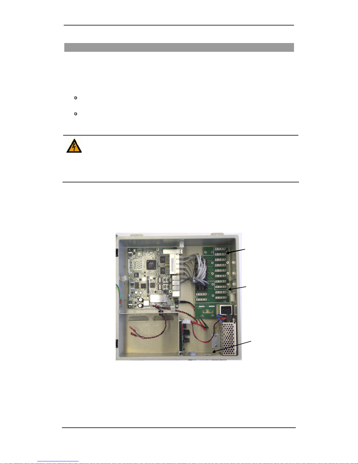
2. Use theType-110 insertion toolto connect the Ethernet wires to L1-L8 connectors on the
PatchPanelas shown in the following table (noticethat the wires and connectors are
color coded):
LAN
Connections
Voice
Connections
Ingress
GW-482S INSTALLATION GUID E
15 MN100143 Rev B
Table 1:LANWire Connections
Connect the - To the -
Orange/White wire Left of the Orange mark
Orange wire Right of the Orange mark
Blue/White wire Left of the Green mark
Blue wire Right of the Green mark
Figure18: Type-110 Tool inserting 10/100BaseT/TX
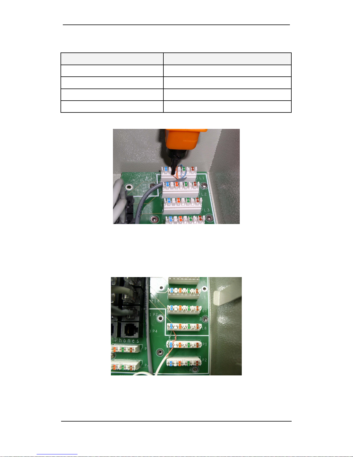
3. Push the DTMF telephone wires through the ingress at the bottom of the unit.
4. Use theType-110 insertion toolto connect the DTMFwires toeither side of the blue
mark on the P1 and P2 connectors on thePatch Panel. Up to 5 phones can be connected in
parallel to each connector. (For GW-482S-4-x you may also connect P3 and P4). See
picture below.
Figure 19: Type-110 Tool inserting DTMF Telephone Wires
5. Plug in theAC connector.
Table of contents
Other Telco Gateway manuals


