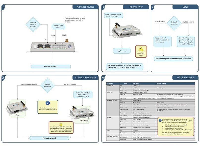
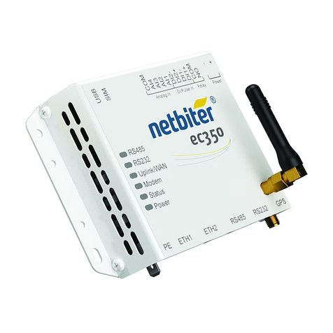
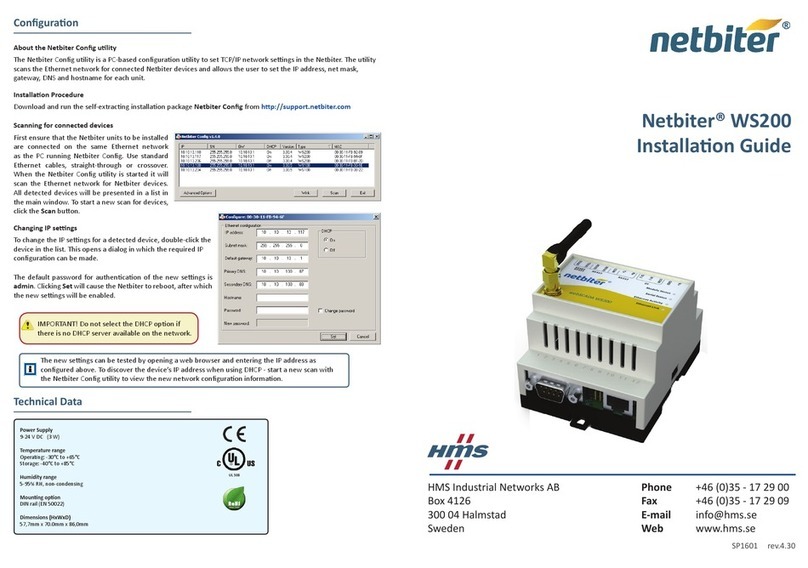
Netbiter Netbiter EasyConnect EC250 User manual

Netbiter
®EC150/220/250 Gateways
USER MANUAL
HMSI-168-92 4.3 ENGLISH

Important User Information
Liability
Every care has been taken in the preparation of this document. Please inform HMS Industrial Networks AB of any
inaccuracies or omissions. The data and illustrations found in this document are not binding. We, HMS Industrial
Networks AB, reserve the right to modify our products in line with our policy of continuous product development.
The information in this document is subject to change without notice and should not be considered as a commit-
ment by HMS Industrial Networks AB. HMS Industrial Networks AB assumes no responsibility for any errors that
may appear in this document.
There are many applications of this product. Those responsible for the use of this device must ensure that all the
necessary steps have been taken to verify that the applications meet all performance and safety requirements in-
cluding any applicable laws, regulations, codes, and standards.
HMS Industrial Networks AB will under no circumstances assume liability or responsibility for any problems that
may arise as a result from the use of undocumented features, timing, or functional side effects found outside the
documented scope of this product. The effects caused by any direct or indirect use of such aspects of the product
are undefined, and may include e.g. compatibility issues and stability issues.
The examples and illustrations in this document are included solely for illustrative purposes. Because of the many
variables and requirements associated with any particular implementation, HMS Industrial Networks AB cannot as-
sume responsibility for actual use based on these examples and illustrations.
Intellectual Property Rights
HMS Industrial Networks AB has intellectual property rights relating to technology embodied in the product de-
scribed in this document. These intellectual property rights may include patents and pending patent applications in
the USA and other countries.
Trademark Acknowledgements
Netbiter®and eWON®are registered trademarks of HMS Industrial Networks AB. Java is a registered trademark of
Oracle and/or its affiliates. All other trademarks are the property of their respective holders.
Copyright © 2016 HMS Industrial Networks AB. All rights reserved.
Netbiter®EC150/220/250 Gateways User Manual
HMSI-168-92 4.3

Netbiter®EC150/220/250 Gateways User Manual HMSI-168-92 4.3
Table of Contents Page
1 Preface ............................................................................................................................... 3
1.1 About This Document.....................................................................................................3
1.2 Related Documents .......................................................................................................3
1.3 Document history...........................................................................................................3
1.4 Conventions ..................................................................................................................4
2 Description ....................................................................................................................... 5
2.1 Netbiter EC150..............................................................................................................5
2.2 Netbiter EC220..............................................................................................................7
2.3 Netbiter EC250............................................................................................................10
2.4 Power Supply ..............................................................................................................13
3 LED Indicators ............................................................................................................... 14
3.1 Netbiter EC150............................................................................................................14
3.2 Netbiter EC220............................................................................................................15
3.3 Netbiter EC250............................................................................................................16
4 Installation ...................................................................................................................... 18
4.1 Netbiter EC150/EC250.................................................................................................18
4.2 Netbiter EC220............................................................................................................18
5 Wiring Examples ........................................................................................................... 19
5.1 Netbiter EC150/EC250.................................................................................................19
5.2 Netbiter EC220............................................................................................................19
6 GPS ................................................................................................................................... 21
6.1 Connecting GPS Devices .............................................................................................21
7 Ethernet Network Setup .............................................................................................. 22
7.1 IP Addressing ..............................................................................................................22
7.2 IPconfig.......................................................................................................................23
8 Activation ........................................................................................................................ 25
8.1 Adding the Gateway to Netbiter Argos ...........................................................................25

Netbiter®EC150/220/250 Gateways User Manual HMSI-168-92 4.3
Table of Contents
9 Local Configuration (EC150/EC250)......................................................................... 26
9.1 Connecting to the Web Server ......................................................................................26
9.2 Login ..........................................................................................................................27
9.3 Status .........................................................................................................................27
9.4 Modbus Settings..........................................................................................................28
9.5 Ethernet Settings .........................................................................................................28
9.6 System Settings...........................................................................................................29
9.7 Netbiter Argos .............................................................................................................30
9.8 Modem Settings (EC250) .............................................................................................31
9.9 GPS Settings (EC250) .................................................................................................31
10 Netbiter Update (EC150/EC250)................................................................................. 32
A EtherNet/IP Implementation ....................................................................................... 35
A.1 Client ..........................................................................................................................35
A.2 Adapter.......................................................................................................................35
B Technical Data................................................................................................................ 37
C Regulatory Compliance............................................................................................... 41

Preface 3 (44)
1 Preface
1.1 About This Document
This manual describes how to install and configure Netbiter EC150/220/250 gateways.
For additional related documentation and file downloads, please visit the Netbiter support web-
site at www.netbiter.com/support.
1.2 Related Documents
Related documents
Document Author
Netbiter EC150/250/220 Installation Guides HMS
Netbiter Argos Administration Manual HMS
Netbiter Remote Access User Manual HMS
1.3 Document history
Revision list
Version Date Author Description
1.00 Nov. 2012 SDa First official release.
1.10 March 2013 SDa New chapter on Ethernet installation.
2.00 Nov. 2013 SDa Added EC350.
2.10 Jan. 2014 SDa Removed EC150-M. Removed info on relay in EC150.
2.11 April 2014 SDa Minor correction to dimensions.
Added Japanese approval information.
2.20 May 2014 SDa Added EC310. Updated LEDs for EC350.
2.30 Sep. 2014 SDa Certifications updated for EC310/EC350.
2.40 Nov. 2014 SDa Added EtherNet/IP support. Updated specs for EC3xx.
2.50 Dec. 2014 ThN Changed tolerance values.
3.00 May 2015 ThN Multiple corrections and updates.
Revised document structure and layout.
3.10 June 2015 ThN Added info on symbolic segment addressing.
4.0 Sep. 2015 ThN New layout
Misc. corrections and updates
4.1 Dec. 2015 ThN Updated for new firmware
Misc. corrections and updates
4.2 June 2016 ThN New IP configuration method for EC310/350
Updated compliance section
5.0 2016-10-03 ThN Removed EC310 and EC350
Summary of changes in this version
Change Where (section no.)
Removed sections about EC310 and EC350 —
Corrected typos and minor errors —
Updated Technical Data appendix
Netbiter®EC150/220/250 Gateways User Manual HMSI-168-92 4.3

Preface 4 (44)
1.4 Conventions
Unordered (bulleted) lists are used for:
• Itemized information
• Instructions that can be carried out in any order
Ordered (numbered or alphabetized) lists are used for instructions that must be carried out in
sequence:
1. First do this,
2. Then open this dialog, and
a. set this option...
b. ...and then this one.
Bold typeface indicates interactive parts such as connectors and switches on the hardware, or
menus and buttons in a graphical user interface.
Monospaced text is used to indicate program code and other
kinds of data input/output such as configuration scripts.
This is a cross-reference within this document: Conventions, p. 4
This is an external link (URL): www.hms-networks.com
This is additional information which may facilitate installation and/or operation.
This instruction must be followed to avoid a risk of reduced functionality and/or
damage to the equipment, or to avoid a network security risk.
Caution
This instruction must be followed to avoid a risk of personal injury.
WARNING
This instruction must be followed to avoid a risk of death or serious injury.
Netbiter®EC150/220/250 Gateways User Manual HMSI-168-92 4.3

Description 5 (44)
2 Description
This product contains parts that can be damaged by electrostatic discharge (ESD).
Use ESD protective measures to avoid equipment damage.
Field wiring terminals shall be connected with minimum wire size 24 AWG.
Netbiter EasyConnect gateways can be connected to Modbus devices via various interfaces
and physical connections. Which interface(s) to use is selected in Netbiter Argos.
2.1 Netbiter EC150
2.1.1 Terminal block (12-pin)
Fig. 1 Terminal block
Terminal block connections
Pin Label Function Note
24 Vin+ Power 9–24 VDC/VAC EC150 can optionally be powered by 9–24 VAC.
23 Vin- PE ground
22 DI:DI 2 Digital input #2 Low = 0–2 VDC, High = 10–24 VDC
21 DI:DI 1 Digital input #1 Low = 0–2 VDC, High = 10–24 VDC
20 DI:COM Digital input common
17 RS-232:RX RS-232 Receive
16 RS-232:TX RS-232 Transmit
15 COM Serial interface common Shared between RS-232 and RS-485
14 RS-485:A RS-485 Line A
13 RS-485:B RS-485 Line B
Netbiter®EC150/220/250 Gateways User Manual HMSI-168-92 4.3

Description 6 (44)
2.1.2 D-sub Connector
The 9-pin male D-sub connector provides an RS-232 interface for Modbus RTU.
6 9
51 (male)
Fig. 2 D-sub connector
D-sub connector pin layout
Pin Function
1 CD (Carrier Detect)
2 Rx (Receive)
3 Tx (Transmit)
4 DTR (Data Terminal Ready)
5GND
6 DSR (Data Set Ready)
7RTS (Request To Send)
8 CTS (Clear To Send)
9 RI (Ring Indicator)
2.1.3 Ethernet Connector
The RJ-45 socket provides Ethernet network connection. It also supports Modbus TCP via
Ethernet, which can be used at the same time as Modbus RTU units on another interface.
1 8
Fig. 3 Ethernet connector
Ethernet connector pin layout
Pin Function
1 TD+
2 TD-
3 RD+
4, 5, 7, 8 Termination
6 RD-
Netbiter®EC150/220/250 Gateways User Manual HMSI-168-92 4.3

Description 7 (44)
2.2 Netbiter EC220
2.2.1 Terminal Block (12-pin)
Fig. 4 Terminal block
Terminal block pin layout
Pin Function Note
+Vdc Power 12–24 VDC
GND PE ground
AO:OUT Analog output 0–10 VDC
AO.COM Analog output common Internally connected to GND
AI:AI 1 Analog input #1 PT100, current or voltage (selected with internal switch)
AI:AI 2 Analog input #2
AI:COM Analog input common Internally connected to GND
DI:DI1 Digital input #1 Low = 0–1 VDC, High = 9–24 VDC
DI:DI2 Digital input #2
DI:COM Digital input common
Relay:COM Relay output common
Relay:NO Normally open connected Rated load: 1 A @ 24 VDC
Analog Input Configuration Switches
Fig. 5 EC220 DIP switch
The analog inputs are configured with two DIP switches inside the unit. Take care not to dam-
age the antenna cable when opening/closing the cover.
EC220 DIP switch setting
Setting Function Note
PT100 Temperature sensor (default) -50 to +150 °C
0–20 mA Current Input resistance 270 Ω
0–10 VDC Voltage Input resistance 280 Ω
Netbiter®EC150/220/250 Gateways User Manual HMSI-168-92 4.3

Description 8 (44)
2.2.2 RS-485 Serial Interface (3–pin Connector)
The RS-485 serial interface can be used to connect Modbus RTU devices.
Fig. 6 RS-485 connector
RS-485 connector pin layout
Pin Function
A RS-485 A line
B RS-485 B line
COM RS-485 common
2.2.3 D-sub Connector
The 9-pin female D-sub connector provides an RS-232 interface for Modbus RTU and for con-
necting a GPS receiver.
9 6
15 (female)
Fig. 7 D-sub connector
D-sub connector pin layout
Pin Function
1 CD (Carrier Detect)
2 Rx (Receive)
3 Tx (Transmit)
4 DTR (Data Terminal Ready)
5GND
6 DSR (Data Set Ready)
7RTS (Request To Send)
8 CTS (Clear To Send)
9 RI (Ring Indicator)
2.2.4 Antenna Connector
The antenna connector is a standard SMA screw connector. Optional external antennas are
available from your supplier.
Netbiter®EC150/220/250 Gateways User Manual HMSI-168-92 4.3

Description 9 (44)
2.2.5 SIM Card
Installing the SIM Card
1. Push the yellow button next to the SIM card holder and remove the holder.
Fig. 8 Removing the SIM card holder
2. Place the SIM card into the holder and insert it into the EC220. Observe the correct po-
sition of the cut-off corner and the contact surfaces.
Fig. 9 Inserting the SIM card
SIM Card configuration
The SIM card must be configured in Netbiter Argos before it can be used.
When using a SIM card not issued by HMS, make sure that the SIM card has a mobile data plan
and allows text messaging and that PIN code security has been disabled.
See the Netbiter Argos Administration Manual for further information.
An SMS text message will be sent to Netbiter Argos when a new SIM card is inserted into the
Netbiter gateway.
Netbiter®EC150/220/250 Gateways User Manual HMSI-168-92 4.3

Description 10 (44)
2.3 Netbiter EC250
2.3.1 Terminal Block (12-pin)
Fig. 10 Terminal block
Terminal block pin layout
Pin Label Function Note
24 V+ Power 9–24 VDC
23 GND PE ground
22 DI:COM Digital input common
21 DI:DI 1 Digital input #1 Low = 0–2 VDC, High = 10–24 VDC
20 DI:DI 2 Digital input #2 Low = 0–2 VDC, High = 10–24 VDC
19 RS-232:RX RS-232 Receive
18 RS-232:TX RS-232 Transmit
17 COM Serial interface common Shared between RS-232/422/485
16 RS-422:RD(A) RS-422 Receive A
15 RS-422:RD(B) RS-422 Receive B
14 RS-485:TD(A)
RS-422:TD(A)
RS-485 Line A
RS-422 Transmit A
13 RS-485:TD(B)
RS-422:TD(B)
RS-485 Line B
RS-422 Transmit B
2.3.2 D-sub Connector
The 9-pin D-sub connector provides an RS-232 interface for Modbus RTU and for connecting a
GPS receiver.
6 9
51 (male)
Fig. 11 D-sub connector
D-sub connector pin layout
Pin Function
1 CD (Carrier Detect)
2 Rx (Receive)
3 Tx (Transmit)
4 DTR (Data Terminal Ready)
5GND
6 DSR (Data Set Ready)
7RTS (Request To Send)
8 CTS (Clear To Send)
9 RI (Ring Indicator)
Netbiter®EC150/220/250 Gateways User Manual HMSI-168-92 4.3

Description 11 (44)
2.3.3 Ethernet Connector
The RJ-45 socket provides Ethernet network connection. It also supports Modbus TCP via
Ethernet, which can be used at the same time as Modbus RTU units on another interface.
1 8
Fig. 12 Ethernet connector
Ethernet connector pin layout
Pin Function
1 TD+
2 TD-
3 RD+
4, 5, 7, 8 Termination
6 RD-
2.3.4 Antenna Connector
The antenna connector is a standard SMA screw connector. Optional external antennas are
available from your supplier.
Netbiter®EC150/220/250 Gateways User Manual HMSI-168-92 4.3

Description 12 (44)
2.3.5 SIM Card
Installing the SIM Card
1. Push the yellow button next to the SIM card holder and remove the holder.
Fig. 13 Removing the SIM card holder
2. Place the SIM card into the holder and insert it into the EC250. Observe the correct po-
sition of the cut-off corner and the contact surfaces.
Fig. 14 Inserting the SIM card
SIM Card configuration
The SIM card must be configured in Netbiter Argos before it can be used.
When using a SIM card not issued by HMS, make sure that the SIM card has a mobile data plan
and allows text messaging and that PIN code security has been disabled.
See the Netbiter Argos Administration Manual for further information.
An SMS text message will be sent to Netbiter Argos when a new SIM card is inserted into the
Netbiter gateway.
Netbiter®EC150/220/250 Gateways User Manual HMSI-168-92 4.3

Description 13 (44)
2.4 Power Supply
Always make sure that the power supply is correctly connected and of the
recommended type. Connecting power with reverse polarity or using the wrong
type of power supply may damage the equipment.
2.4.1 Netbiter EC150/EC250
Fig. 15 EC150/EC250 power supply connection
Connect 9–24 VDC to Vin+ (EC150) or V+ (EC250), and connect ground to GND.
Netbiter EC150 can alternatively be powered by 9–24 VAC.
2.4.2 Netbiter EC220
Fig. 16 EC220 power supply connection
Connect 9–24 VDC to +VDC, and connect ground to GND.
Netbiter®EC150/220/250 Gateways User Manual HMSI-168-92 4.3

LED Indicators 14 (44)
3 LED Indicators
3.1 Netbiter EC150
Fig. 17 EC150 LED indicators
LED Indication Meaning
Module Status
OFF No power
Orange/green System is starting up
Green (3 flashes) System is operating normally
Red (2 flashes) Invalid network settings
• DHCP: Check that there is a working DHCP server on
the network.
• Static IP: Check that the IP address, default gateway and
DNS are correctly set.
• If a proxy is used, check that the proxy settings are
correct.
Red (3 flashes) No connection to Netbiter Argos
• Check the network settings.
• If a proxy is used, check that the proxy settings are
correct.
• Check that at least one of ports 443, 80 or 5222 are open
in the firewall.
Serial Link Status
Flashing green Receiving serial packet
Flashing red Transmitting serial packet
Activity/Collision Flashing green Receiving Ethernet packet
Flashing red Ethernet collision
Link Steady green 10 Mbps Ethernet network detected
Steady orange 100 Mbps Ethernet network detected
Netbiter
®EC150/220/250 Gateways User Manual HMSI-168-92 4.3

LED Indicators 15 (44)
3.2 Netbiter EC220
All LED indicators will be lit while the gateway is starting up. After the startup sequence has
completed they will indicate system status.
Fig. 18 EC220 LED indicators
LED Indication Meaning
Power Off No power
Green (steady) Unit has power
Status Off Normal operation
Red (1 flash) SIM card not registered on HMS Home Network
1
• Check that the SIM card is correctly inserted and undamaged
and that PIN security is disabled.
• Check that there is mobile network coverage for your operator.
Red (2 flashes) Invalid network settings
• Check that the correct APN (Access Point Name) has been set in
Netbiter Argos.
Red (3 flashes) No connection to Netbiter Argos
• Check that the mobile network provider grants access to port
5222.
Running Off Contact Netbiter support
Green (flashing) Normal operation
GSM Signal Off Contact Netbiter support
Green (1 flash) Poor mobile network signal
• Make sure the antenna is correctly installed and pointing
upwards.
• Try a different antenna placement.
• Use an external antenna.
Green (2 flashes) Acceptable mobile network signal
Green (3 flashes) Good mobile network signal
Netbiter®EC150/220/250 Gateways User Manual HMSI-168-92 4.3
1. The Netbiter SIM card will automatically try to connect to a network in the global HMS “home network” group of opera-
tors. A list of these network operators can be found at the Netbiter support website.

LED Indicators 16 (44)
3.3 Netbiter EC250
Fig. 19 EC250 LED indicators
The Module Status LED alternates between displaying system status and mobile network signal
strength for 2 seconds each in a 4-second cycle. If a mobile network connection has not been
set up, the LED will stay unlit during the second part of the cycle.
LED Indication Meaning
Module Status (1)
OFF No power
Orange/green System is starting up (ca. 40 seconds)
Red (1 flash) SIM card not registered on HMS Home Network2
• Check that the SIM card is correctly inserted and undam-
aged, and that PIN security is disabled.
• Check that there is mobile network coverage for your
operator
Red (2 flashes) Invalid network settings
Mobile
• Check that the correct APN (Access Point Name) has
been set in Netbiter Argos.
Ethernet
• DHCP: Check that there is a working DHCP server on
the network.
• Static IP: Check that the IP address, default gateway and
DNS are correctly set.
• If a proxy is used, check that the proxy settings are
correct.
Red (3 flashes) No connection to Netbiter Argos
Mobile
• Check that the mobile network provider grants access to
port 5222.
Ethernet
• Check the network settings.
• If a proxy is used, check that the proxy settings are
correct.
• Check that at least one of ports 443, 80 or 5222 are open
in the firewall.
Netbiter®EC150/220/250 Gateways User Manual HMSI-168-92 4.3
2. The Netbiter SIM card will automatically try to connect to a network in the global HMS “home network” group of opera-
tors. A list of these network operators can be found at the Netbiter support website.

LED Indicators 17 (44)
LED Indication Meaning
Module Status (2)
Green (1 flash) Poor mobile network signal
• Make sure the antenna is correctly installed and pointing
upwards.
• Try a different antenna placement.
• Use an external antenna.
Green (2 flashes) Acceptable mobile network signal
Green (3 flashes) Good mobile network signal
Serial Status
Steady orange System is starting up
Flashing green Receiving serial packet
Flashing red Transmitting serial packet
Ethernet Activity Flashing green Receiving Ethernet packet
Ethernet Link Steady green 10 Mbps Ethernet network detected
Steady orange 100 Mbps Ethernet network detected
Netbiter®EC150/220/250 Gateways User Manual HMSI-168-92 4.3

Installation 18 (44)
4 Installation
This product contains parts that can be damaged by electrostatic discharge (ESD).
Use ESD protective measures to avoid equipment damage.
4.1 Netbiter EC150/EC250
Netbiter EC150 and EC250 are supplied ready for mounting on a DIN rail.
4.1.1 Mounting on DIN Rail
Mounting
Fig. 20 Mounting on DIN rail
1. Hook the unit onto the upper lip of
the rail.
2. Press the unit towards the rail until it
snaps into place.
Removing
Fig. 21 Removing from DIN rail
1. Pull the tab at the bottom of the unit
gently downwards (using a screw-
driver or similar tool).
2. Pull the bottom end free and lift the
unit from the rail.
4.2 Netbiter EC220
Fig. 22 DIN rail mounting kit (optional)
Netbiter EC220 can either be screw-mounted directly to a flat surface using the screw holes in
the metal housing, or on a DIN rail using the optional rail mounting kit.
Netbiter®EC150/220/250 Gateways User Manual HMSI-168-92 4.3
This manual suits for next models
5
Table of contents
Other Netbiter Gateway manuals
