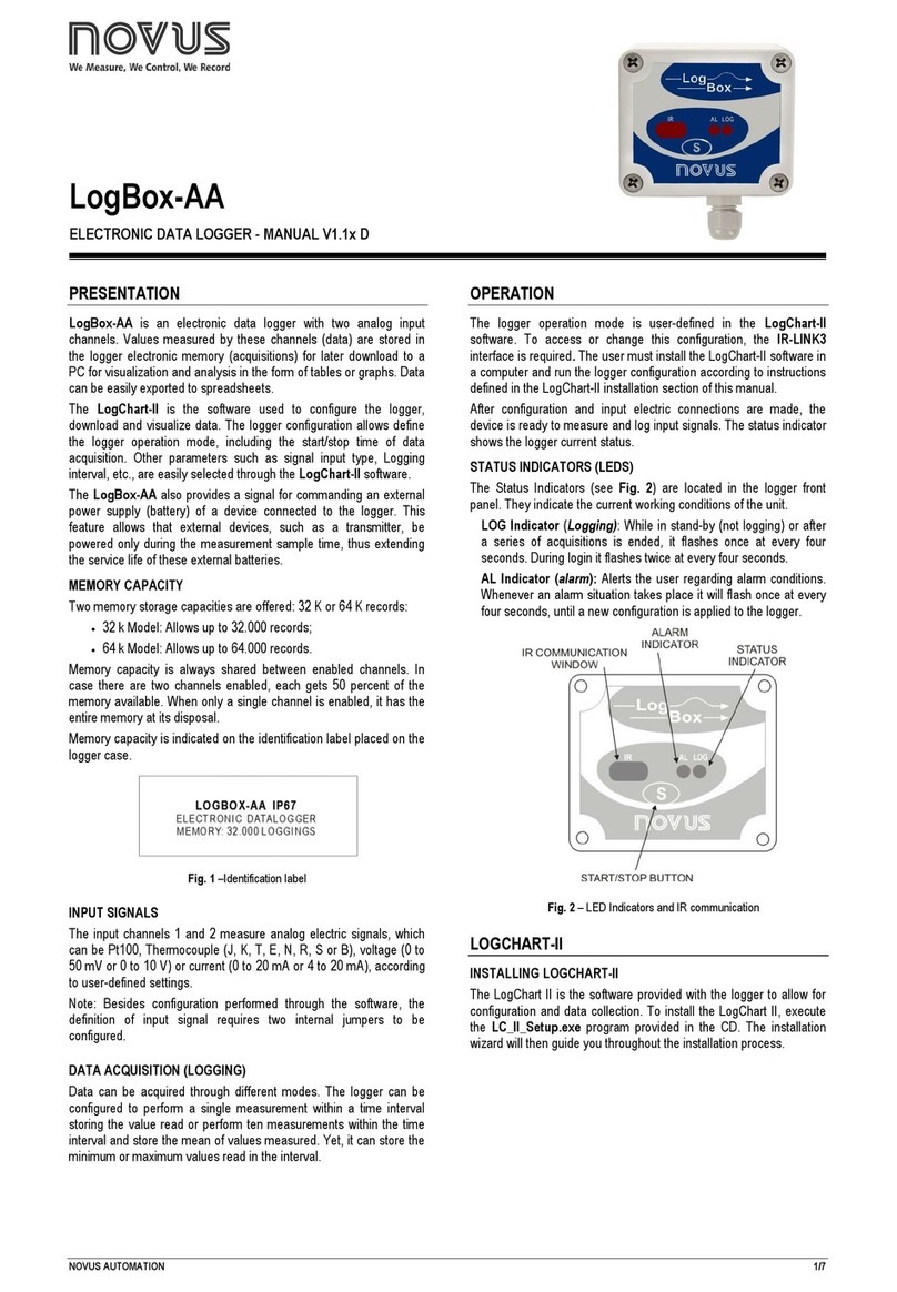
headway VDR User manual

Service Manual
VDR/SVDR
Qingdao Headway Marine Technology Co., Ltd.
Tel: (+86) – 532 - 88702807/88702808 Fax: (+86) – 532 - 83107816
Add: F4,5#Building Area A Huite Industrial City, 177#, Zhuzhou Road, Qingdao, China

1Hardware
The basic design is the same for the HMT-S100 SVDR and HMT-100 VDR. The only difference is more interface
on the VDR Main Cabinet Unit.
The contents of this manual, if not specified, the contents of SVDR and VDR are common
This is the Main Cabinet Unit

This is the Power Supply Unit:

This is the Remote Alarm Panel:
This is the PDC:
Fixed PDC

This is the float PDC
This is the Remote Acquisition Unit:

2Faulttypeandtheservice
All the alerts could be divided four styles:
1Channel Error likes GPS, Gyro, microphone and so on;
2 Power alert;
3 PDC connect error;
4 Not Receive Inf;
2.1Channel&Microphoneerror
2.1.1Channelerror
When the channel error appears, the first step is to press the “Mute” & “ACK FLASH” to stop alarm sound. Then
check whether related equipment is on, whether the plug of the input is loose and whether the connection is good. If
the connection is good, we should check whether the related equipment can send signals to VDR. After the failure
is eliminated, the displayed information of Remote Alarm Panel screen will disappear automatically.
2.1.2Microphoneerror
Please switch off the power and take out the CF card in the Main Cabinet Unit. I mean the PROGRAM DISK. It is
behind of the BACKUP DISK. Insert the CF card in to the CF card reader. As following:
Open “My Computer” and find the CF card. Double click it and you will find the “data” folder, Open the “data”

folder and you will see the following page. Please double click the icon.
Please run the “VDRConfig.exe” and choose the “Audio Configuration” as following:
Please press the “Alt + U” to active the other items as following:

Please note to choose the “off” on the microphone. And then click to save it. The “Save OK” will
be shown after clicking.
2.1.3ZDAAlarm
Please switch off the power and take out the CF card in the Main Cabinet Unit. I mean the PROGRAM DISK. It is
behind of the BACKUP DISK. Insert the CF card in to the CF card reader. As following:

Open “My Computer” and find the CF card. Double click it and you will find the “data” folder, Open the “data”
folder and you will see the following page. Please double click the icon.
You will see the following page
Please choose “Uart Configuration”

Please press “Alt +U”, the page will be changed:
Please cancel the choice. I mean to make to disappeared. As following:

And then please click the . The “Save OK” will be shown on the left of it. Like this
Then please insert the CF card into the Main Cabinet Unit and switch on it.
2.1.4RadarImageadjust.
Please switch off the power and take out the CF card in the Main Cabinet Unit. I mean the PROGRAM DISK. It is
behind of the BACKUP DISK. Insert the CF card in to the CF card reader. As following:

Open “My Computer” and find the CF card. Double click it and you will find the “data” folder, Open the “data”
folder and you will see the following page. Please double click the icon .
You will see the following page

Please press “Alt+R”, you will find you could change the “Cmp Res” and “H_Offset”. You could adjust the
H_Offset and the V_Offset. You could change the both items to adjust the picture. Of course, you should click the
“Save Radar CFG” to save the new configuration.
2.1.5BackupDiskFull
Please switch off the power, take out the CF card and insert into the CF card reader. As following:

Connect it to the laptop. Open “My Computer” and right click the CF card disk. Choose the “Format”
Please set the configuration as following picture, please note the Files system should be “Fat 32”. And click “start”

When format is ok, please build the “data” folder into the CF card.
There should build “audio” folder, “other” folder and “picture” folder under the “data” folder.
2.2PowerAlert
Please note there is four foot for the PSU output. And foot 4 is GND. And the power is foot 2. Usually the voltage
between foot 4 and foot 2 is DC24V. The system could not be started if this voltage is 0V.
The voltage for foot 1 and foot 3 rules as below:
1 When the AC appears on the Remote Alarm Panel:
Foot 1: DC24V;
Foot 2: DC24V;
Foot 3: DC0V;
2 When the ShIPDC appears on the Remote Alarm Panel;
Foot 1: DC24V;
Foot 2: DC24V;
Foot 3: DC24V;

3 When the VDRDC appears on the Remote Alarm Panel;
Foot 1: DC0V;
Foot 2: DC24V;
Foot 3: DC24V;
This is the PSU PCB
PCB 1

DC Power:
X10: Red X11: Black
Battery:
X2: Black X1: Red
Lamp:
X8: Red X9: Black
Output:
X3: Blue X4: Red X5: Yellow X6: N/A X7: Black
PCB 2:
AC Power:
X12: Red X13: Black X14: Yellow
When “SHIPDC” appears here, it indicates that the 110/220V power has been cut off, and the SVDR system is
powered by the emergency power of the vessel. We can press “ACK FLASH” to stop flashing, press “Mute” to stop
buzzing and search for the causes. First, check if the power supply is still charged with electricity, and the
connection is good or not. If the connection is good, after plugging in the main power supply, the Remote Alarm
Panel will indicate AC power supply. In case of emergency, in order to save PDC data, it is necessary to press both
“ACK FLASH and TEST buttons at the same time until “backup 01” appears on the screen, and the data of latest
12 hours will be saved in the big Backup Disk forever. After successful backup, “BACKUP 01” will appear on the
screen. “SYSTEM OK” indicates that the system is working normally.

2.3PDCconnecterror
When the “PDC Connect Error” appears, please remove the failure according to the below steps
1 Check the lamps status.
Switch off the power and check the “N1-N5” lamps status. If the “N2” lamp is light, please format the PDC
directly.
2 “N2” lamp is off or the format fails.
2-1. Check the cable
If the N2 lamp is off and the cable is normal, please change the PDC.
Please first check the PDC plug type, which is used on Fixed PDC.

If the PDC plug is new type as above picture. Please check the voltage between the plug 5 and plug 6, which should
be the DC24V.
MCU Plug-------------------------------------------PDC Plug
Plug1-------------------------------------------Plug1
Plug2-------------------------------------------Plug2
Plug3-------------------------------------------Plug3
Plug4-------------------------------------------Plug4
Plug5-------------------------------------------Plug5
Plug6-------------------------------------------Plug6
This is the old type PDC plug, which is used on Float PDC.
If the PDC plug is old type as above picture. Please check the voltage between the plug 6 and plug 7, which should
be the DC24V
MCU Plug-------------------------------------------PDC Plug
Plug1-------------------------------------------Plug1
Plug2-------------------------------------------Plug2
Plug3-------------------------------------------Plug3
Plug4-------------------------------------------Plug5
Plug5-------------------------------------------Plug6
Plug6-------------------------------------------Plug7
If the PDC cable is damaged, please repair the cable. If the PDC cable is normal and N2 lamp is light, please
continue the step 2-2.

2-2 Simulate the PDC with the laptop.
If the PDC cable is normal, we could use our laptop to simulate the PDC. If the SVDR works normally after
connection, it proves that the MCU works normally.
Please simulate the PDC according to the following steps:
2-2-1.Double Click “wftpd32.exe”
2-2-2.Please choose “Security→Users/rights”
This manual suits for next models
1
