manuals.online logo
Brands
  1. Home
  2. •
  3. Brands
  4. •
  5. Red Valve
  6. •
  7. Control Unit
  8. •
  9. Red Valve 2600 Series User manual

Red Valve 2600 Series User manual

Red Valve’s Series 2600 pinch valve and Series
2633 small diameter inline check valve are
the simplest valves available to industry. They
have only four parts and require little or no
maintenance. These valves are designed with
threaded end connections for easy installation
and removal on small lines up to 3” in diameter. A
spare replacement sleeve should be ordered when
the valve is placed in service.
NOTE: 2” and 3” PVC Series 2600’s may have
hose clamps on the body of the valve. These
clamps must be loosened when removing the
sleeve.
IMPORTANT
Please take a moment to review this manual. Before performing any maintenance on the valve be sure
that the pipeline has been depressurized. The improper installation or use of this product may result in
personal injury, product failure, or reduced product life. Red Valve Company can accept NO liability resulting
from the improper use or installation of this product. If you have any questions or problems, please call the
customer service hotline at (412) 279-0044. We appreciate your comments. Thank you for choosing Red Valve.
Series 2600 Pinch Valve / Series 2633 Inline Check Valve
Installation, Operation and Maintenance Manual
IOM RV02.02-1
February 2023
AIR CLOSING PRESSURE
Internal Air Closing Air Closing
Valve Line Pressure Pressure
Size Pressure PGR Synthetic
(in.) (psi) (psi) (psi)
1/8” — 1/2” 75 29 35
3/4” — 1” 75 31 39
1-1/4” 50 31 39
1-1/2” — 2” 50 37 44
* Note: Closing pressures are to be added to line pressure.
3. PRESSURE REGULATORS
To avoid over-pressurizing the valve when closing, a
pressure regulator should be installed. Pressure in ex-
cess of 50 psi above pipeline pressure can tear the rub-
ber at the ange. Higher pressures require the sleeves to
be reinforced with berglass short threads.
INSPECTION OF PRODUCT
INSTALLATION
Before installing, be sure the pipe threads are clean. A
sealing material such as pipe dope can be used. Direction
of ow is indicated on the 2633. Be sure that it is in the
proper orientation before installing.
FLOW
1. INSTALLING VALVE
Use a wrench to tighten the valve by turning the end caps.
Turning the body can damage the rubber inside. Once in-
stalled, if a small gap exists between the body and end cap,
do not tighten further. This can twist the rubber ange inside
and cause damage.
GapGap
2. AIR SUPPLY PORT
Air supply is connected to the 1/4” NPT port. This port is
normally plugged on the 2633, but can be used as a drain
or piped as a ush port. Use the chart below to determine
the correct air pressure needed to close the 2600.
The ridge molded into
the rubber ange must
be pressed into the
groove in the seat. use a
dull blade to pry up one
edge of the ange and
snap the ange into place. Firmly push into place around the
entire ange.
2633: The new duckbill
sleeve is simply inserted
into the body. Make sure
that the ridge on the
rubber ange properly ts
into the groove in the seat
by rmly pressing into
place around the entire ange.
4. REINSTALL END CAPS
To reinstall the end caps, lubricate the exposed rubber ange
and tighten the end cap until snug. Do not overtighten or the
rubber ange may twist or tear. Caps will not bottom out on
the valve body.
1. REMOVE VALVE
Remove the valve from the pipeline using a wrench to turn the
end caps. Do not grip the valve body! A spare replacement
sleeve should be placed on order when this valve is placed in
service.
2. REMOVE SLEEVE
2600: Unscrew both end caps from
the body. Pry one side of either rubber
ange out of its seat with a dull blade or
screwdriver. Fold this edge over into the
center of the sleeve and push the ange
fully through the seat. Pull the sleeve out
of the body.
2633: Unscrew the end cap on the inlet side of the valve. Pry
one side of the rubber ange up using a screwdriver or dull
blade and pull up to remove the duckbill sleeve from the valve
body. The other rubber seal will only need to be changed if
seriously worn.
3. REPLACE SLEEVE
2600: Lubricate the new sleeve
with soapy water. Pinch the sides
of one ange together and squeeze
through the seat. Push the sleeve
through the valve body. Carefully
pull the ange through the opposite
seat. Do not use sharp tools or
screwdrivers.
REPLACING SLEEVES
Red Valve • 750 Holiday Drive, Suite 400, Pittsburgh, PA 15220 • 412-279-0044 • [email protected] • RedValve.com
© 2023 Red Valve Company
Limited Warranty
Red Valve Company (“Seller”) manufactured products, auxiliaries and parts thereof that we manufacture for a period of twenty-four (24) months from
date of shipment from Seller’s factory, are warranted to the original purchaser only against defective workmanship and material, but only if properly
stored, installed, operated, and serviced in accordance with Seller’s recommendations and instructions.
For items proven to be defective within the warranty period, your exclusive remedy under this limited warranty is repair or replacement of the defective
item, at Seller’s option, FCA Incoterms 2020 Seller’s facility with removal, transportation, and installation at your cost.
Products or parts manufactured by others but furnished by Seller are not covered by this limited warranty. Seller may provide repair or replacement
for other’s products or parts only to the extent provided in and honored by the original manufacturer’s warranty to Seller, in each case subject to the
limitations contained in the original manufacturer’s warranty.
No claim for transportation, labor, or special or consequential damages or any other loss, cost or damage is being provided in this limited warranty.
You shall be solely responsible for determining suitability for use and in no event shall Seller be liable in this respect.
This limited warranty does not warrant that any Seller product or part is resistant to corrosion, erosion, abrasion or other sources of failure, nor does
Seller warrant a minimum length of service.
Your failure to give written notice to us of any alleged defect under this warranty within twenty (20) days of its discovery, or attempts by someone other
than Seller or its authorized representatives to remedy the alleged defects therein, or failure to return product or parts for repair or replacement as
herein provided, or failure to store, install, or operate said products and parts according to the recommendations and instructions furnished by Seller
shall be a waiver by you of all rights under this limited warranty.
This limited warranty is voided by any misuse, modification, abuse or alteration of Seller’s product or part, accident, fire, flood or other Act of God, or
your failure to pay entire contract price when due.
The foregoing limited warranty shall be null and void if, after shipment from our factory, the item is modified in any way or a component of another
manufacturer, such as but not limited to; an actuator is attached to the item by anyone other than a Seller factory authorized service personnel.
All orders accepted shall be deemed accepted subject to this limited warranty, which shall be exclusive of any other or previous warranty, and this
shall be the only effective guarantee or warranty binding on Seller, despite anything to the contrary contained in the purchase order or represented by
any agent or employee of Seller in writing or otherwise, notwithstanding, including but not limited to implied warranties.
THE FOREGOING REPAIR AND REPLACEMENT LIMITED WARRANTY IS IN LIEU OF ALL OTHER WARRANTIES, OBLIGATIONS AND
LIABILITIES, INCLUDING, BUT NOT LIMITED TO, ALL WARRANTIES OF FITNESS FOR A PARTICULAR PURPOSE OR OF MERCHANTABILITY
OR OTHERWISE, EXPRESSED OR IMPLIED IN FACT OR BY LAW, AND STATE SELLER’S ENTIRE AND EXCLUSIVE LIABILITY AND YOUR
EXCLUSIVE REMEDY FOR ANY CLAIM IN CONNECTION WITH THE SALE AND FURNISHING OF SERVICES, GOODS OR PARTS, THEIR
DESIGN, SUITABILITY FOR USE, INSTALLATION OR OPERATIONS. NEITHER ANY PERFORMANCE OR OTHER CONDUCT, NOR ANY ORAL OR
WRITTEN INFORMATION, STATEMENT, OR ADVICE PREPARED BY SELLER OR ANY OF OUR EMPLOYEES OR AGENTS WILL CREATE A
WARRANTY, OR IN ANY WAY INCREASE THE SCOPE OR DURATION OF THIE LIMITED WARRANTY.
Limitation of Liability
IN NO EVENT SHALL SELLER BE LIABLE FOR ANY DIRECT, INDIRECT, SPECIAL, PUNITIVE, EXEMPLARY, OR CONSEQUENTIAL DAMAGES
(INCLUDING, BUT NOT LIMITED TO, DAMAGE TO OR LOSS OF OTHER PROPERTY OR EQUIPMENT, BUSINESS INTERUPTION, COST OF
SUBSTITUTE PRODUCTS, LOSS OF TIME, LOSS PROFITS OR REVENUE, COST OF CAPITAL, LOSS OF USE, OR DIMINUTION IN VALUE)
WHATSOEVER, AND SELLER’S LIABILITY, UNDER NO CIRCUMSTANCES, WILL EXCEED THE CONTRACT PRICE FOR THE GOODS AND/OR
SERVICES FOR WHICH LIABILITY IS CLAIMED. ANY ACTION FOR BREACH OF CONTRACT BY YOU, OTHER THAN RIGHTS RESPECTING OUR
LIMITED WARRANTY DESCRIBED ABOVE, MUST BE COMMENCED WITHIN 12 MONTHS AFTER THE DATE OF SALE.
Sales and Service
For information about our worldwide locations, approvals, certifications and local representative:
Web site: RedValve.com E-Mail: [email protected]
750 Holiday Drive, Suite 400, Pittsburgh, PA 15220 • Phone: 412-279-0044
Red Valve Company reserves the right to incorporate our latest design and material changes without notice or obligation.
Design features, materials of construction and dimensional data, as described in this manual, are provided for your information only
and should not be relied upon unless confirmed in writing by Red Valve Company. Certified drawings are available upon request.
February 2023

This manual suits for next models

1

Other Red Valve Control Unit manuals

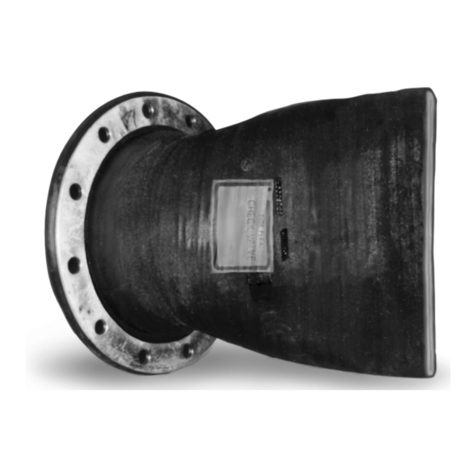
Red Valve Tideflex Series User manual

Red Valve

Red Valve Tideflex Series User manual

Red Valve Tideflex Series User manual

Red Valve

Red Valve Tideflex Series User manual

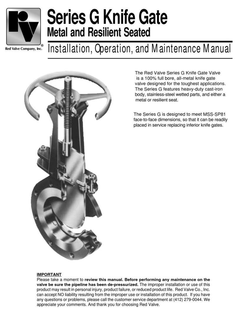
Red Valve G Series User manual

Red Valve

Red Valve G Series User manual

Red Valve 75 Series User manual

Red Valve

Red Valve 75 Series User manual

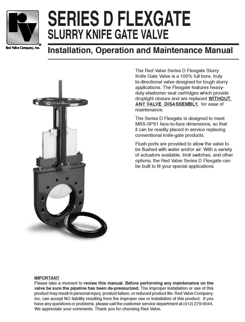
Red Valve Flexgate D series User manual

Red Valve

Red Valve Flexgate D series User manual

Red Valve Tideflex 35 Series User manual

Red Valve

Red Valve Tideflex 35 Series User manual

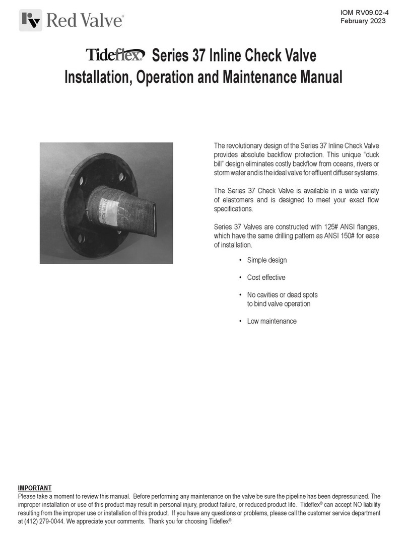
Red Valve TIdeFlex 37 Series User manual

Red Valve

Red Valve TIdeFlex 37 Series User manual

Red Valve Tideflex Series User manual

Red Valve

Red Valve Tideflex Series User manual

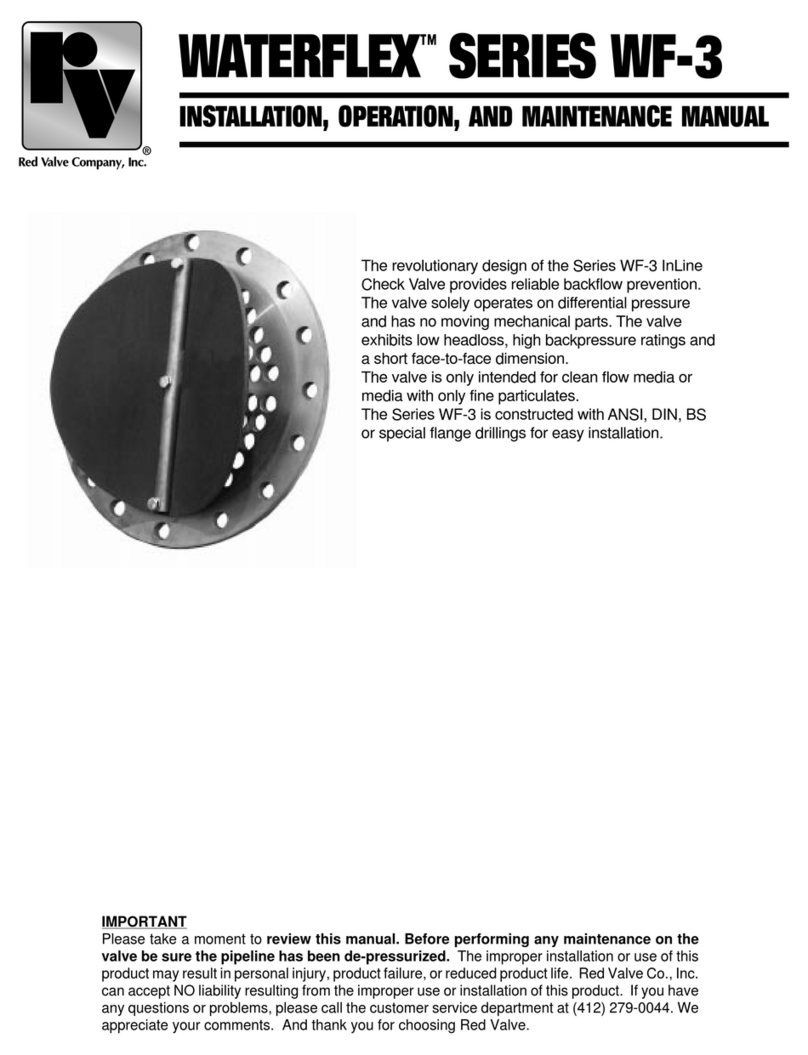
Red Valve WATERFLEX SERIES WF-3 Installation and operating instructions

Red Valve

Red Valve WATERFLEX SERIES WF-3 Installation and operating instructions

Popular Control Unit manuals by other brands

Commell ADP-3460 user manual

Commell

Commell ADP-3460 user manual

SKYLUX Skycom Skymax CE 24V/5A User manual and installation instructions

SKYLUX

SKYLUX Skycom Skymax CE 24V/5A User manual and installation instructions

Heatscope MHS-SM2200 Original installation and instruction manual

Heatscope

Heatscope MHS-SM2200 Original installation and instruction manual

AMX HPX-1600 installation manual

AMX

AMX HPX-1600 installation manual

LS ELECTRIC XGT Series user manual

LS ELECTRIC

LS ELECTRIC XGT Series user manual

Quectel LPWA Series Hardware design

Quectel

Quectel LPWA Series Hardware design

NARVI BASIC Installation and instruction manual

NARVI

NARVI BASIC Installation and instruction manual

urmet domus 1043 instructions

urmet domus

urmet domus 1043 instructions

Texas Instruments LED171596AEVM user guide

Texas Instruments

Texas Instruments LED171596AEVM user guide

Gemtek Goldcrest user guide

Gemtek

Gemtek Goldcrest user guide

Task Force Tips Low Profile Ball Intake Valve Instructions for installation, safe operation and maintenance

Task Force Tips

Task Force Tips Low Profile Ball Intake Valve Instructions for installation, safe operation and maintenance

MADDALENA Arrow WAN 2 Instructions for installation, use and maintenance

MADDALENA

MADDALENA Arrow WAN 2 Instructions for installation, use and maintenance

SimCom SIM900B EVB Application note

SimCom

SimCom SIM900B EVB Application note

Little Giant TM830 installation instructions

Little Giant

Little Giant TM830 installation instructions

Fire-Lite MDF-300 installation instructions

Fire-Lite

Fire-Lite MDF-300 installation instructions

EP Solar Tracer1215BN instruction manual

EP Solar

EP Solar Tracer1215BN instruction manual

B meters RFM-TX2 manual

B meters

B meters RFM-TX2 manual

LogiCO2 0475 Installation instruction

LogiCO2

LogiCO2 0475 Installation instruction

manuals.online logo
manuals.online logoBrands
  • About & Mission
  • Contact us
  • Privacy Policy
  • Terms and Conditions

Copyright 2025 Manuals.Online. All Rights Reserved.